You now own the finest Water Treatment System available to homeowners. To enjoy the maximum benefits of this system, please read the contents of this Owners Manual.
SYSTEM INFORMATION
POWER REQUIREMENTS
The computer board receives power from an external wall-mount transformer, supplied with each system.
Voltage: The voltage supplied to the computer board is 24V AC.
Frequency: The line frequency is 50 Hz or 60 Hz.
WATER PRESSURE
A minimum of 20 pounds of water pressure is required for proper operation of the system. The stated operating pressure range is 20 psi – 120 psi (138 kPa – 828 kPa).
BYPASS VALVE
The bypass valve enables the customer to bypass the system in situations of: emergency leaks in the equipment, service calls and/or outdoor water use.
TEMPERATURE OPERATING RANGES
Operating Temperature Range: 40° F – 100° F (4.4° C – 38° C)
Storage Range: The computer board can be stored at temperatures from -20°C (-4°F) to 70°C (158°F).
Humidity: The computer board operates properly with relative humidity from 10% to 95%, non- condensing.
ENVIRONMENTAL REQUIREMENTS
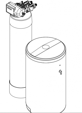
Location: The water softener and control cannot be exposed to outdoor elements, such as direct sunlight or atmospheric precipitation. The system may be installed in a covered, open-air structure such as a carport, residential or commercial building. Weather covers are also available through the Order Department ( part number 72370 ).
OPERATIONAL SPECIFICATIONS
| UNIT SIZE | MODEL | SERVICE FLOW RATE (GAL/MIN) | PSI DROP AT SERVICE FLOW RATE | DRAIN FLOW RATE (GAL/MIN) | SALT PER REGENERATION (LBS) | CAPACITY AT LOW SALT SETTING(GRAINS) | CAPACITY AT MEDIUM SALT SETTING(GRAINS) | CAPACITY AT HIGH SALT SETTING(GRAINS) | EFFICIENCY (GRAINS/LB. OF SALT) |
| 1.0 | PENTAIR WATER SOFTENING SYSTEM 1.0 | 11.6 | 12 | 2.5 | 3.9 – 15.6 | 17500 | 25200 | 33500 | 4487 |
| 1.5 | PENTAIR WATER SOFTENING SYSTEM 1.5 | 11.9 | 15 | 2.5 | 5.2 – 23.4 | 24300 | 37000 | 48600 | 4637 |
| 2.0 | PENTAIR WATER SOFTENING SYSTEM 2.0 | 13.2 | 15 | 3.5 | 7.5 – 30.0 | 34600 | 50400 | 64000 | 4613 |
APPLICATION LIMITATIONS
• This system may be applied on municipality or well water systems. On hardness levels of 60 grains and higher, the system may not achieve a hardness of less than 1 grain, due to high Total Dissolved Solids. (Some bleed through is possible.) Bleed through can also be caused by Sodium levels higher than 1000 ppm. In either case, your system can be programmed to minimize these effects.
• When this system is installed on water with ferrous iron, also known as clear water iron, the maximum range of reduction is based on local water conditions. The range is generally below 3 parts per million. Your equipment may require special programming, along with an additive to the brine tank, to maximize the equipment’s ability to reduce iron.
MAINTENANCE REQUIREMENTS
SALT RECOMMENDATIONS
Two kinds of salt are recommended for water conditioners:
- Block Salt: Water conditioner block salt is reasonably priced, low in impurities and will not cake in the salt container. Block Salt is pressed into the shape of a cattle block.
- Solar Salt: Solar Salt is 98% pure salt, reasonably priced and low in impurities. Solar Salt is in the shape of pellets.
THE REGENERATION VALVE
The regeneration valve is designed to last many years, but from time to time it may be necessary to clean and lubricate the moving parts. Your water quality and the amount of regenerations necessary will affect this maintenance schedule.
TESTING THE WATER
The water should be tested periodically (2 times a year minimum) with hardness test strips to ensure that the system is performing accurately. Additional test strips can be purchased from the Order Department. Test strip order number: 38306 pack of 50 test strips.
PRE-INSTALLATION INSTRUCTIONS
• Do not install this system where water is microbiologically unsafe or of unknown quality without adequate disinfection before or after the system.
• This system must be installed in an area that is not affected by extreme heat, cold or the elements. The selected installation area must be adequate for easy service of all parts.
• This system must be installed in accordance with all applicable state and local laws and regulations.
• This system is designed to treat cold water only and can be installed on any cold water supply.
INSTALLATION INSTRUCTIONS
- SAFETY PRECAUTIONS
• To prevent accident or injury, do not hoist the unit over your shoulder. Use a hand truck to transport the unit. Note: Do not lay the unit on its side during transportation and/or installation.
• Wear safety glasses and work gloves during installation and service. - TEST THE WATER HARDNESS
• The test strip provided is for testing the water hardness after the installation is complete to ensure the system is functioning properly and for periodic testing. When programming the control it is necessary to know the exact water hardness in grains per gallon. If you are using municipal water,
your local water providers should be able to give you the hardness level. If you are using water from a private well, if may be necessary to have the water tested locally. - CHECK WATER PRESSURE
• Use a pressure gauge to confirm that the water pressure does not exceed 120 psi. If the water pressure does exceed this limit, install a pressure regulator on the inlet pipe of the unit. The minimum pressure for a conditioner is 20 psi. 60 psi is the optimum operating pressure. - LOCATE A SITE FOR THE UNIT
• There are three primary requirements needed for a site: the main water source, a drain (the drain may be a floor drain, a sewer trap, utility sink, vent stack, dry well, etc., depending on local plumbing codes) and an electrical connection. Locate the system as close to these items as practical. Avoid
drain lines over 25 feet long. In most applications, bypass any outside faucets.
• Place the unit in the desired location. The location must have a level, smooth surface.
• If the system is located outdoors, protect the unit from direct sunlight. (Direct sunlight can damage the fiberglass and other system components.) If necessary, build a box or shed. Note: The system can only be installed outdoors in climates that do not reach freezing levels. - TURN OFF THE WATER AND DRAIN THE PLUMBING
• Turn off the water at the meter or the pressure tank.
• Drain all the pipes. Do not sweat the pipes with water in them; steam will damage plastic parts in the valve.
• To drain the plumbing system, open all the faucets in the house and flush the toilets. This procedure will allow air to enter the plumbing system. The water will drain out of the lowest faucet or outlet. - BYPASS THE OUTSIDE FAUCETS
•When possible it is best to bypass the outside faucets. However in some cases the outside faucets can not be accessed. In this situation the bypass valve should be used whenever watering outside for extended periods of time. If the installation is outside or in a garage a faucet can be installed on the inlet water side to provide an option for untreated water. - CONNECT THE PLUMBING TO THE BYPASS VALVE AND BRINE TANK
• Do not point the soldering torch directly at the system. The thermo-plastic material will last a lifetime, within normal operating temperatures, but will melt in a torch flame.
• To prevent hot water from backing up into the conditioner, avoid short connections of pipe between the conditioner and the hot water heater. If you can’t avoid a short connection, move the equipment to another location. As a last resort, install a check valve. If the check valve causes “water hammer”, install a water hammer suppressor.
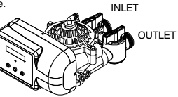
• Connect the raw water pipe to the INLET pipe connection of the bypass valve. When looking at the front of the unit, the inlet is the pipe connection on the LEFT side of the valve.
• Connect the treated water pipe to the OUTLET pipe connection of the bypass valve. When looking at the front of the unit, the outlet is the pipe connection on the RIGHT side of the valve.
• Install the brine line to the brine tank.
- PLUMBING GROUND CONNECTION
• In some homes, metal piping may serve as a ground connection for the home electrical system. Installing a Pentair Softener with its nonmetallic valve body will interrupt the ground connection. Whenever a system is installed on metallic plumbing, we recommend you use grounding pipe clamps
and a ground cable to maintain continuity of the ground connection from the inlet to the outlet pipe. 1⁄4” bare stranded wire is recommended for the ground cable. Check electrical continuity of the connection after installation. - INSTALL THE DRAIN LINE AND AIR GAP (AIR GAP NOT INCLUDED WITH THE UNIT)
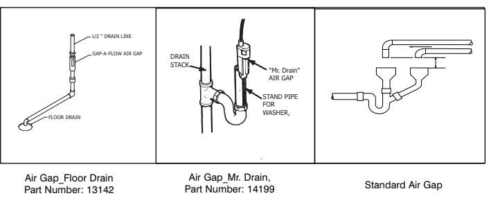
• Using the supplied drain line fitting use Teflon tape on the threads and attach to the top of the valve. Run 1/2 inch I.D. flexible drain line tubing ( not supplied) to an appropriate drain. Most local codes require an air gap. See pictures below.
Note: Drain line may be plumbed with rigid pipe or PEX, If required by local code. The drain connection on the valve will accommodate any standard 3/4 inch NPT fitting.
•If you wish to use an air gap device (not included) you may purchase one from the Order Department.
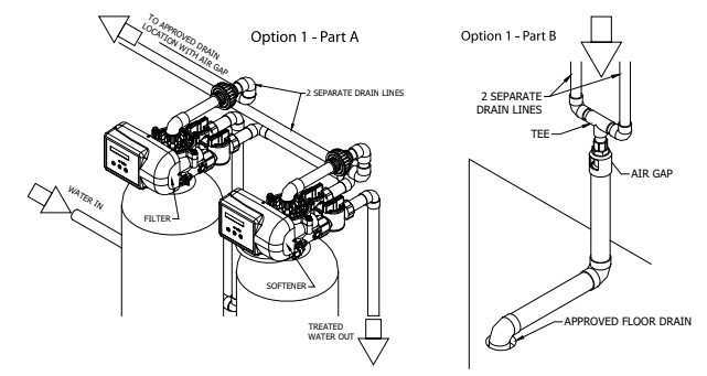
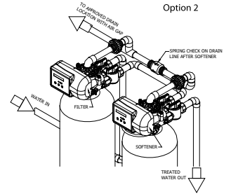
Special Attention for situations where a Filter and a Softener are installed together:
When a whole house filter and a softener are installed side by side, the preferred approach is to run a separate drain line from each unit all the way to the point of termination. If this is not done, there is the potential for drain water from the filter to back feed through the softener and overfill the brine tank, especially when drain lines are run overhead. (Please note that back feed goes only into the brine tank, not the service line.)
If circumstances require you to tie the drain lines together, please use one of the following methods to avoid back feed issues:
Option 1: Run the drain lines from both systems to the point of termination, and tee them together before the air gap. (See figures below)
Option 2: Install a PVC check valve with a light spring on the Softener side to prevent back flow to the Softener. (See figure below)
CONTROL INFORMATION
POWER ON LED
A green LED is ON when power is applied to the control and the microprocessor is operating properly.
SERVICE REQUIRED
If the message “For Service Call” or “Service Required” displays in the window of the control without showing the time of day, the control valve has encountered a problem, such as failure to reach the proper position during regeneration. The valve, the motor assembly, and board must be checked to diagnose and fix this problem.
Note: It is normal for the message ‘For Service Call’ followed by a phone number to scroll across the second line of the display. The time of day & capacity remaining will appear on line 1 during normal operation.
TIME CLOCK
The time clock maintains the time of day for an extended period of time in the event of power loss. A super capacitor provides this function and eliminates the need of a battery. In the event the power is off past the charge of the capacitor only the time of day is lost. The rest of the programming is stored in the memory and will not need to be reprogrammed. When the power is restored the clock will restart at 8 AM and will need to be reset.
REGENERATION
Once an immediate regeneration is requested, a complete regeneration must occur to clear the request. Once the regeneration starts, it must finish or the computer board will not clear. Manually walk (scroll) the control through regeneration to clear the computer board. If the regeneration is aborted and the request is not cleared, another immediate regeneration will occur.
HIGH-SPEED MOTOR OPERATION IN THE REGENERATION MODE
High-speed motor operation is achieved while stepping the control through the regeneration cycle. Pressing the scroll button a second time, while in regeneration, activates the higher speed.
PROGRAM LEVELS
To enter any of the program levels, the control must display the time of day and gallons of capacity
remaining (Service Mode).
The system have three program levels available:
- The Installer’s Level: To access the Installer’s Level, you must enter the five key sequence code located .
- The End User’s Level: The End User’s Level does not require a special code to access.
- The Diagnostic Level
HOW TO PROGRAM THE INSTALLER’S LEVEL
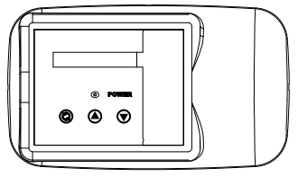
KEY BUTTONS:

SCROLL BUTTON

UP ARROW

DOWN ARROW
To begin, verify that the control is in the Service Mode.

• Press the DOWN ARROW and hold it for 5 seconds; the control will display:

• Within 10 seconds, enter the following key sequence:
DOWN ARROW
DOWN ARROW
SCROLL BUTTON
DOWN ARROW
The control is now in the Installer’s Level. Use the SCROLL BUTTON to advance through the different settings.
The following settings are available in the Installer’s Level:
1.UNIT SIZE
The control will display:

• Press the UP or DOWN ARROW to select a different unit size. Available units are 0.75,1.0, 1.5 and 2.0.
Press the SCROLL BUTTON to advance to the next setting.
2.HARDNESS
The control will display:

• Press the UP or DOWN ARROW to set the number to the correct incoming hardness, in grains per gallon. The setting range is 1-99.
NOTE: If you have iron in the water or very high total dissolved solids, you can increase this number for better performance.
Press the SCROLL BUTTON to advance to the next setting.
3.SALT LEVEL
The control will display:

• Press the UP or DOWN ARROW to select Low, Medium, or High. Medium is a good setting for most circumstances. For small families and low hardness, Low will provide greater salt efficiency. For large families and high hardness, High will provide the most capacity.
Press the SCOLL BUTTON to advance to the next setting.
4.SERVICE PHONE NUMBER
The control will display:

If you do not want to change the phone number, leave this setting at NO. Press SCROLL to advance to the next setting.
To change the number, select YES; Press the UP or DOWN ARROW and then enter the service phone number. Press Scroll to advance through the digits. After setting the number, press SCROLL to advance to the next setting.
5.TIME OF DAY
The control will display:

• Press the UP or DOWN ARROW to program the time of day.
Press SCROLL BUTTON to advance to the next setting
The control will display:

If you want to go to advanced setting, press the UP or DOWN ARROW, change to YES and press the scroll button.
If you do not want to access advance setting, leave this at NO. Press Scroll to advance to Exit screen.

Press the DOWN ARROW to exit the Installer’s Level.
Note: If you need to recheck settings or make a change, pressing SCROLL when “EXIT” is displayed will take you back to the start of Installer Settings.
IMPORTANT NOTE: TO ACTIVATE THE NEW SETTINGS, YOU MUST EXECUTE A COMPLETE REGENERATION. IF YOU DO NOT MANUALLY REGENERATE THE SYSTEM, THE SETTINGS WILL NOT BECOME ACTIVE UNTIL THE UNIT HAS COMPLETED THE NEXT SCHEDULED REGENERATION.
ADVANCED MENU
1.RESET AVERAGE
The control will display:

• If you want to reset the average daily volume, press the UP or DOWN ARROW to select YES.
•If YES is selected, the control will reset the average volume per day to 25 % of the capacity.
Press the SCROLL BUTTON to advance to the next setting.
2.RESERVE CAPACITY
The control will display:

• The reserve capacity will be calculated automatically, based on the registered daily water consumption. The initial setting is 25% of the capacity, which will adjust over time to accurately reflect daily water use.
• If you prefer, you can select a Fixed Reserve. While at the Reserve screen when “variable” is flashing, press the UP OR DOWN ARROW.
The control will display:

• To adjust the reserve, press the SCROLL BUTTON. Use the UP OR DOWN ARROW to set the reserve capacity in increments of 10 gallons, up to 70% capacity of the bed.
• To calculate the reserve capacity, take the number of people in the home and multiply it by 70 gallons per day. The reserve capacity will equal one day of water use. Example: 3 people X 70 gallons per day = 210 gallons (suggested reserve capacity)
Press the SCROLL BUTTON to advance to the next setting.
3.TIME OF REGENERATION
The control will display:

• Press the UP or DOWN ARROW to adjust the time of regeneration.
Regeneration should be set for a time when water use is minimal. 2:00 AM is good for most households.
Note: The system diverts hard water to the home during regeneration. If any water is drawn during regeneration, some hard water will enter the plumbing system and possibly the hot water tank. Keep in mind that the regeneration cycle can last up to two hours after the starting time.
Press the SCROLL BUTTON to advance to the next setting.
4.DAYS OVERRIDE
The control will display:

• Press the UP or DOWN ARROW to set the number of days between regenerations. The setting range is OFF to 30 days.
Note: In most situations with a meter equipped valve, override can remain “OFF”. Set a number if days if you wish to have the system regenerated periodically regardless of water use.
Press the SCROLL BUTTON to advance to the next setting.
5.CYCLE 1 – BACKWASH
The control will display:

6.CYCLE 2 – BRINE/SLOW RINSE
The control will display:

Press the Up or Down ARROW to change the length of the brine/slow rinse cycle. The minimum length is preselected based on unit size and salt level, and cannot be reduced. The maximum setting is 99 minutes.
Press Down Arrow to exit Installer’s Mode.

IMPORTANT NOTE: TO ACTIVATE THE NEW SETTINGS, YOU MUST EXECUTE A COMPLETE REGENERATION. IF YOU DO NOT MANUALLY REGENERATE THE SYSTEM, THE SETTINGS WILL NOT BECOME ACTIVE UNTIL THE UNIT HAS COMPLETED THE NEXT SCHEDULED REGENERATION.
HOW TO PROGRAM THE END USER’S LEVEL
To began, verify that the control is in the Service Mode:

Press the SCROLL BUTTON to advance to the next setting.
The following settings are available in the End User’s Level:
1.TIME OF DAY
The control will display:

• Press the UP or DOWN ARROW to program the time of day.
Press the SCROLL BUTTON to advance to the next setting.
2.IMMEDIATE REGENERATION MODE
The control will display:

• If the control is left in this position, the timer will countdown from 10 to 0, initiating a regeneration at 0.
• To avoid an immediate regeneration, press the SCROLL BUTTON before the timer reaches 0.
Press the SCROLL BUTTON to advance to the next setting.
3.DELAYED REGENERATION MODE
The control will display:

• If the control is left in this position, the unit will regenerate at the programmed time. The display will remain in the Delayed Regeneration Mode until the regeneration has begun.
• To cancel the Delayed Regeneration Mode, press the SCROLL BUTTON.
Press the SCROLL BUTTON to return to the Service Mode.
UNDERSTANDING THE DIAGNOSTIC LEVEL
To begin, verify that the control is in the Service Mode.

• Press the UP ARROW and hold it for 5 seconds; the control will display:

The control is now in the Diagnostic Level. Use the SCROLL BUTTON to advance to each diagnostic. If no button is pressed within 5 minutes, the display will return to the Service Mode.
The following items are available in the Diagnostic Level (Read Only):
• Regen _ Days Ago: Displays how many days ago the unit last regenerated.
• In Srvc: Displays how many days the control has been in service.
• # of Regens: Displays the number of regenerations that have taken place since the control was first installed.
• Tot Vol: Displays the total volume of water used since installation.
• Last Rgn @: Displays the amount of water used before the last regeneration.
• Flow Rate: Displays the current flow rate.
• Avg Vol: Displays the average daily water consumption.
• Water Hard: Displays the amount of hardness programmed into the control.
• Rsrv: Displays whether the control is programmed for a Fixed or Variable Reserve.
• Regen @: Displays the time of day the unit will regenerate.
• Override: Displays the override mode by reading “OFF” or the number of days programmed into the control.
• Backwash: Displays the minutes of backwash programmed into the control.
• BRN/RNS: Displays the minutes of brine and slow rinse programmed into the control.
• FILL/RNS: Displays the minutes of fast rinse and brine refill programmed into the control. This is calculated based on unit size and salt level, and is not settable by the user.
• Units: English – US
• Salt Level: Displays the amount of salt ( Low, Medium, or High) for regeneration.
• M P Resets: Displays how many times the control has lost power.
• Memory Reset: Displays how many times the control lost power long enough to lose the time of day.
• SP1Sc PlumbR20: Displays the current program.
To exit the Diagnostic Level, press the DOWN ARROW at the EXIT display.
SYSTEM START UP INSTRUCTIONS
- Confirm the system is plumbed in correctly: inlet on left, outlet on right.
- DO NOT add salt yet. If you made any mistakes, make the necessary corrections before continuing with the startup procedure.
- When turning the water back on to the house, leave system in bypass mode. Then turn water on to house and check for leaks. Run the cold water in bathtub to flush debris and air from lines. (Bathtubs do not have aerators that may plug with debris.)
- Press the SCROLL button 2 times. The display will start a 10 second count down. At zero the motor will start and advance to cycle 1. Wait for the motor to stop in cycle 1, then slowly open the inlet valve partially to purge air from tank. Allow to run until there is a steady flow of water at the drain. Once all
air is purged you may open inlet fully. - Press the SCROLL button to advance to the next cycle. Motor will start and advance to cycle 2. Wait for it to stop. Disconnect brine line at brine tank to confirm suction by placing thumb on the end of the tubing, and then reconnect brine line to brine float.
- Press the SCROLL button to advance to the next cycle. Motor will start and advance to cycle 3. Wait for the motor to stop. Confirm water is filling tank, lift up on the float in the brine tank and check all fittings for leaks (water leaks will cause brine tank overfill). Once you complete this step you may
now open outlet on bypass. - Press the SCROLL button to advance to the home position. The control will display home screen. Press the scroll button 2 times. The 10 second countdown will begin and regeneration cycle will start again. Wait for motor to stop at cycle 1, then advance by pressing scroll button 1 time. Wait for motor to stop at cycle 2, then advance to cycle 3 by pressing scroll button 1 time. Leave in cycle 3 for the duration of the cycle. Confirm refill and add salt to tank. The system will add the correct of water to the salt tank.
- Go to faucet. Run cold water 5-10 minutes and test hardness. Run cold water until you achieve soft water. While the water is running, check the gallons remaining on the home screen and verify that the number is decreasing. This will confirm that the system is counting gallons. Run a faucet on the
hot water side until it runs cold to drain hot water tank. If you do not want to waste water and skip this step, it will take some time to exchange all the untreated water in the plumbing and hot water tank.
SANITIZING THE SOFTENER
Note: The unit may be sanitized with or without salt in the brine tank.
After the installation is complete, the following procedure can be used to sanitize the water conditioner:
- Mix a 3/4 cup of common (unscented) 5.25% household bleach with 1 quart of water. Pour this solution into the brine well. Note: Do not pour undiluted bleach into the water conditioner.
- Initiate a manual regeneration. The solution will be drawn into the water conditioner during the regeneration process.
- When the regeneration is complete, the water conditioner has been sanitized.
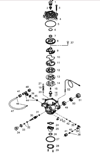
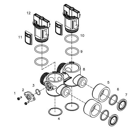
VALVE EXPLODED VIEW
| ITEM | QUANTITY | PART # | DESCRIPTION |
| 1 | 1 | 70793 | 3/4” NPTF TO 1/2” I.D. HOSE MALE DRAIN ELBOW |
| 2 | 1 | 75053 72175 | BACKWASH FLOW CONTROL 2.5 GPM (UNIT SIZE 1.0 & 1.5) BACKWASH FLOW CONTROL 3.5 GPM (UNIT SIZE 2.0) |
| 3 | 6 | 72678 | SCREW 1/4-20 X 1-1/4 LG HEX WASHER HD |
| 4 | 1 | 71083 | VALVE BODY COVER |
| 5 | 1 | 70658 | VALVE COVER O-RING |
| 6 | 1 | 72327 | WASHER |
| 7 | 1 | 70665 | TEFLON O-RING |
| 8 | 1 | 71089 | WORM GEAR |
| 9 | 1 | 71087 | CAM SHAFT |
| 10 | 1 | 70656 | ROTOR O-RING |
| 11 | 1 | 71132 | ROTOR PLATE |
| 12 | 1 | 71084 | SEAL DISK |
| 13 | 1 | 71182 | INSERT PLATE |
| 14 | 1 | 71183 | GASKET |
| 15 | 1 | 71006 | FLOAT VALVE SPRING |
| 16 | 1 | 71127 | FLOAT VALVE |
| 17 | 1 | 70660 | FLOAT VALVE O-RING |
| 18 | 1 | 72770 | VALVE BODY ROTARY GEN-3 W/INSERTS |
| 19 | 1 | 71063 71064 | INJECTOR #1 (UNIT SIZE 1.0 & 1.5) RED INJECTOR #2 (UNIT SIZE 2.0) YELLOW |
| 20 | 1 | 70655 | INJECTOR O-RING LOWER |
| 21 | 1 | 70664 | INJECTOR O-RING UPPER |
| 23 | 1 | 71947 | SPRING CLIP |
| 24 | 1 | 71344 | RISER INSERT GASKET |
| 25 | 1 | 71118 | RISER INSERT |
| 26 | 1 | 70662 | RISER TUBE O-RING |
| 27 | 1 | 70663 | TANK O-RING |
| 28 | 1 | 71010 | ADAPTER RING |
| 29 | 2 | 71512 | SCREW 6-20 X 21/32 LG SS |
| 30 | 1 | 71060 | WORM DRIVE SHAFT |
| 31 | 1 | 70616 | WORM DRIVE SHAFT WASHER |
| 32 | 2 | 70666 | WORM DRIVE SHAFT O-RING |
| 33 | 1 | 70661 | PACKING GLAND O-RING |
| 34 | 1 | 72772 | PLASTIC PACKING GLAND ROTARY |
| 35 | 1 | 70667 | O-RING |
| 36 | 1 | 70659 | O-RING |
| 37* | 1 | 70932 | UMBRELLA CHECK VALVE(*OPTIONAL FOR OVERHEAD DRAINS) |
| 38 | 1 | 71124 | BRINE REFILL ELBOW |
| 39 | 1 | 71961 | REFILL ELBOW CHECK BALL 1/4” DIA |
| 40 | 1 | 70984 | REFILL ELBOW SPRING |
| 41 | 2 | 70797 | COMPRESSION NUT FOR 3/8” TUBE JACO |
| 42 | 1 | 71184 | BRINE REFILL FLOW CONTROL |
| 43 | 1 | 70994 70995 | FLOW CONTROL WASHER 0.5 GPM (UNIT SIZE 1.0 & 1.5) FLOW CONTROL WASHER 1.0GPM (UNIT SIZE 2.0) |
| 44 | 1 | 71129 | BRINE TEE |
| 45 | 1 | 70871 | BRINE TEE CHECK BALL 3/8” DIA |
| 46 | 2 | 12625 | 3/8” TUBE SUPPORT |
| 47 | 1 | 13604 | BRINE REFILL TUBE 3/8” O.D.X. 250” I.D. X 12” L |
| 48 | 1 | 70797 | COMPRESSION NUT FOR 3/8” TUBE JACO PG-6 |
| 49 | 1 | 72458 | FLOW DIFFUSER |
| 50 | 1 | 72544 | IMPELLER ASSEMBLY WITH BUSHING |
| 51 | 1 | 72545 | HUB FLOW METER ASSEMBLY |
| 52 | 1 | 72519 | FLOW METER SENSOR CABLE 20” |
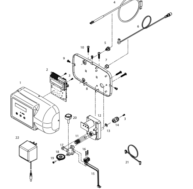
CONTROL EXPLODED VIEW
| ITEM | QUANTITY | PART # | DESCRIPTION |
| 1 | 1 | 39497 | FRONT COVER ASSY, PENTAIR ROTARY |
| 2 | 1 | 38751 | BOARD ASSY SOFTENER WITH 2 LINE DISPLAY |
| 3 | 3 | 70618 | SCREW #4-24 X 3/8 LG SELF-THREADING |
| 4 | 1 | 72519 | FLOW METER SENSOR CABLE NGC |
| 5 | 1 | 72134 | HEYCO BUSHING, SR 5P-4 |
| 6 | 1 | 70971 | POWER LEAD |
| 7 | 1 | 70312 | HEYCO BUSHING, SR 2P-4 |
| 8 | 1 | 70962 | ELECTRONIC CONTROL BACKPLATE |
| 9 | 3 | 71502 | SCREW #8-18 X 3/8 LG, SELF-THREADING |
| 10 | 4 | 71497 | SCREW #10-16 X 1 LG, TYPE BT SS, SELF-THREADING |
| 11 | 1 | 75156 | ROTARY WORM DRIVE GEAR |
| 12 | 1 | 71656 | MOTOR, 24VCD WITH INTERNAL CAPACITORS |
| 13 | 1 | 75158 | 1/4IN E RETAINING RING STAINLESS STEEL |
| 14 | 1 | 75157 | ROTARY WORM COUPLING |
| 15 | 1 | 72451 | MICROSWITCHES SUBASSY 2401 |
| 16 | 2 | 70622 | SCREW #2-28 X 3/4 LG, SELF-THREADING |
| 17 | 1 | 71185 | BRACKET |
| 18 | 1 | 71106 | HUB AND GEAR |
| 19 | 1 | 70625 | SCREW #6-32 X 7/16 LG |
| 20 | 1 | 70965 | CAM SHAFT |
| 21 | 1 | 71679 | MOTOR LEAD |
| 22 | 1 | 72138 | TRANSFORMER 120VAC .5 A |
BYPASS VALVE EXPLODED VIEW AND PARTS LIST
BYPASS VALVE ASSEMBLY PART NUMBER 72668
| ITEM | QUANTITY | PART # | DESCRIPTION |
| 1 | 2 | 72599 | SCREW 6X32X1/2 TYPE |
| 2 | 1 | 72580 | BYPASS END CAP 541 |
| 3 | 1 | 13328 | 017 O-RING 8730 |
| 4 | 2 | 72584 | RETAINING RING VS-15 |
| 5 | 2 | 71161 | 568-363 NUT, BYPASS VALVE |
| 6 | 2 | 71162 | 568-364 RING, NUT RETAINER |
| 7 | 2 | 71110 | 568-320 GASKET |
| 8 | 1 | 72669 | BYPASS BODY ROTARY |
| 9 | 2 | 72585 | O-RING 220 EPC 70 DURO |
| 10 | 2 | 72586 | O-RING 222 EPC 70 DURO |
| 11 | 2 | 72583 | SEAL BYPASS VALVE |
| 12 | 2 | 72670 | BYPASS HANDLE ROTARY |
SYSTEM EXPLODED VIEW AND PART LIST
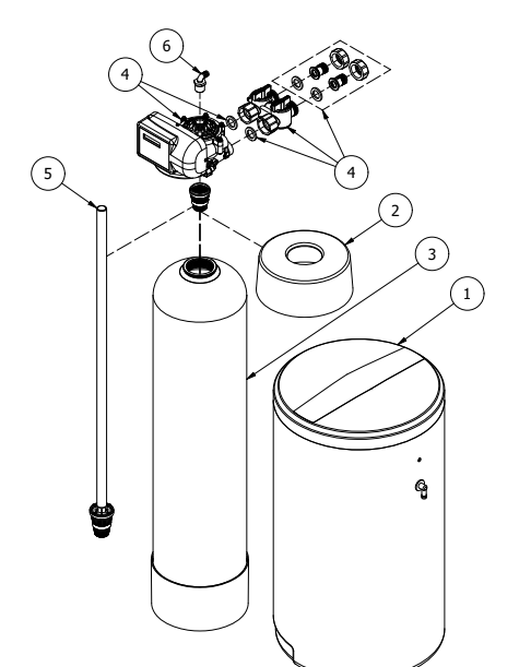
| ITEM | QUANTITY | PART # | DESCRIPTION |
| 1 | 1 | 38571 | BRINE TANK BLACK 18X33 ASSY |
| 2 | 1 | 38946 | 10” PENTAIR PRINTED TANK COLLAR 1.0 & 1.5 |
| 38947 | 12” PENTAIR PRINTED TANK COLLAR 2.0 | ||
| 3 | 1 | 38256 | 10 X 44 TANK BLACK W/BASE 1.0 |
| 38257 | 10 X 54 TANK BLACK W/BASE 1.5 | ||
| 38258 | 12 X 48 TANK BLACK W/BASE 2.0 | ||
| 4 | 1 | 83487 | PENTAIR ROTARY VALVE 1.0 & 1.5 WITH BYPASS |
| 83488 | PENTAIR ROTARY VALVE 2.0 WITH BYPASS | ||
| 5 | 1 | 18961 | RISER PIPE ASSY 1.0 |
| 18962 | RISER PIPE ASSY 1.5 | ||
| 38013 | RISER PIPE ASSY 2.0 | ||
| 6 | 1 | 70793 | 3/4″ NPT TO 1/2 ID ELBOW |
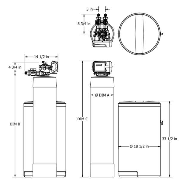
Tank Size DIM A DIM B DIM C
10×44 10×54
| Tank Size | DIM A | DIM B | DIM C |
| 10×44 | 10-1/4 in | 46 in | 51 in |
| 10×54 | 10-1/4 in | 55-7/8 in | 61-1/4 in |
| 12×48 | 12 in | 50 in | 55-1/4 in |
TROUBLESHOOTING GUIDE
| SYMPTOM 1. Hard (untreated) water to service | CAUSE 1. Open bypass valve. 2. Loss of resin. 3. The valve is in regeneration. 4. Excessive water use. 5. Change in raw water hardness. 6. The unit fails to regenerate. 7. The valve fails to draw brine. 8. Decreasing exchange capacity of resin. 9. No salt in the brine tank. 10. Leak between rotor and seal disk. 11. Leak at the riser tube. 12. The valve body and timer are out of synchronization. | SOLUTION 1. Close the bypass valve. 2. Refer to SYMPTOM #9. 3. Wait for the regeneration to complete. 4. Check the frequency of regenerations. 5. Adjust settings accordingly. 6. Refer to SYMPTOM #2. 7. Refer to SYMPTOM #3. 8. Clean or replace the resin bed. 9. Add salt to the brine tank. 10. Check the rotor and seal disk; replace if necessary. 11. Verify that the riser tube is seated correctly and is not cracked. 12. Synchronize the valve body and timer. |
| 2. The unit fails to regenerate | 1. Faulty electrical supply. 2. The control is not set properly. 3. The drive motor is defective. 4. The flow meter is defective. 5. The computer board is defective. 6. The microswitches are defective. | 1. Check the electrical items (fuse, transformer). 2. Verify the correct regeneration schedule and reset the control. 3. Replace the drive motor. 4. Replace the flow meter. 5. Replace the computer board. 6. Replace the microswitches. |
| SYMPTOM 3. The valve fails to draw brine | CAUSE 1. Low operating pressure. 2. The injector is plugged. 3. The injector filter is plugged. 4. The drain line is restricted. 5. The brine line is restricted. 6. Leak in the brine line. 7. Not enough water in the brine tank. | SOLUTION 1. Verify the operating pressure (20 psi min.). 2. Clean the injector. 3. Clean the injector filter. 4. Check the drain line for kinks or restrictions. Verify that the backwash flow control is free of debris. 5. Check the brine line for kinks or restrictions. 6. Check the brine line and connections for leaks. 7. Refer to SYMPTOM #6. |
| 4. The valve cycles continuously | 1. Defective or shorted microswitch(es) | 1. Replace the microswitch(es) |
| 5. Excessive water in the brine tank | 1. The valve fails to draw brine. 2. Improper or missing brine refill flow control. 3. Leak between the rotor and seal disk. | 1. Refer to SYMPTOM #3. 2. Verify that the flow control is installed and properly sized. 3. Check the rotor and seal disk; replace if necessary. |
| 6. The valve fails to refill the brine tank | 1. Blockage in the brine line or brine valve. 2. Improper or missing brine refill flow control. 3. Plugged brine refill flow control. | 1. Remove the blockage. 2. Verify that the flow control is installed and properly sized. 3. Remove the debris. |
| SYMPTOM | CAUSE | SOLUTION |
| 7. The unit uses too much salt | 1. Excessive water in the brine tank. 2. The unit regenerates too frequently. | 1. Refer to SYMPTOM #5. 2. Check the hardness, salt, reserve capacity and calendar override settings. |
| 8. Salt water to service | 1. Excessive water in the brine tank. 2. Low water pressure. | 1. Refer to SYMPTOM #5. 2. Check the injector size and increase the brine/slow rinse time. |
| 9. Loss of resin through the drain line | 1. Excessive backwash/fast rinse flow. 2. The lower and/or upper distributor is damaged. 3. A leak between the riser tube and upper distributor. | 1. Verify that the backwash flow control is installed and sized correctly. 2. Replace the distributor(s). 3. Verify that the riser tube is seated correctly and is not cracked. |
| 10. Loss of water pressure | 1. Mineral or iron build up in the resin tank. 2. Plugged lower and/or upper distributor. 3. Crushed lower and/or upper distributor. 4. Plugged the riser pipe. | 1. Clean the resin bed and control valve. Increase the regeneration frequency. 2. Remove the debris from the distributor(s). 3. Replace the distributor(s). 4. Remove and clean the riser pipe. |
| 11. Constant water flow to the drain | 1. Drive motor failure. 2. Computer board failure. 3. Defective microswitch(es). 4. The valve body and timer are out of synchronization. | 1. Replace the drive motor. 2. Replace the computer board. 3. Replace the microswitch(es). 4. Defective microswitch(es). |
READ ALSO: NORTH STAR WATER CONDITIONER MODEL NSC15ED USER’S MANUAL
Water Treatment Systems Limited Product Warranty
STATEMENT OF LIMITED PRODUCT WARRANTY
Limited Warranty Coverage
For Pentair product(s) Softeners and Tank filters. The products are warranted to be free from defects in material and/or workmanship under normal use and service for the following:
The Resin/Media tank and Brine tank (if applicable), will carry a ten (10) year warranty from the date of shipment. The valve body will also carry a (10) year warranty. The Media will carry a five (5) year warranty on municipal water, and a one (1) year warranty on well water. The electrical will carry a five (5) year warranty. Any replacement product(s) provided by Pentair pursuant to this Limited Warranty will be warranted only for the remainder of the original limited warranty period or thirty (30) days from the date of shipment, whichever is longer.
The following are specifically excluded from the Limited Warranty coverage provided herein:
• Defects or problems not reported to Pentair during the applicable warranty period.
• Any products manufactured by other companies that are used in connection with Pentair product.
• Problems resulting from the alteration, modification, misuse, abuse, neglect, improper care, maintenance or negligent use, including but not limited to unprotected outdoor installation of any Pentair product.
Procedure for Obtaining Limited Warranty Coverage
In order to obtain the benefits of this Limited Warranty, defective part(s) and/or product(s) must be returned to Pentair as soon as possible after discovery of the defect, but not later than the expiration date of the warranty period provided in this Limited Warranty. The Technical Service Department at Pentair will issue a Warranty Return Authorization (WRA) number for the defective part(s) or product(s) which must be clearly marked on the outside of the package being returned. Packages must be shipped freight prepaid, along with a letter stating the part number, serial number, if any, the date of purchase of the item which is claimed to be defective and a brief description of the problem detected. Pentair is not responsible under this Limited Warranty for any cost incurred for shipping or transportation in connection with the return of the part(s) or product(s).
Repair or Replacement
Upon receipt of the product and warranty claim, Pentair will verify the reported failure and determine if the part(s) or product(s) is/are covered by this Limited Warranty. If this Limited Warranty applies, Pentair will, at its option, repair or replace the part(s) or product(s).
No Liability for Consequential Damages
Unless otherwise required by applicable law, Pentair shall not be liable for any damages whatsoever (including without limitation, loss time, inconvenience, expenses such as telephone calls, labor or material charges incurred in connection with the removal or replacement of the part(s) or product(s), special, incidental, consequential, or indirect damages for personal injury, loss of business profits, business interruption, loss of business information, or any other pecuniary loss) arising out of the use of or inability to use the defective part(s) or product(s), even if Pentair has been advised of the possibility of such damages. Pentair entire liability under any provision of this Limited Warranty shall be limited to the amount actually paid for the part(s) or product(s).
NOTE: Because some states/jurisdictions do not allow the exclusion or limitation of incidental or consequential damages, the above limitation or exclusion may not apply.
No Other Warranties:
Pentair specifically disclaims all other warranties, either express or implied, including, but not limited to implied warranties of merchantability and fitness for a particular purpose, with regard to the part(s), product(s) and/or any accompanying written materials. This limited warranty gives you specific legal rights. You may have other rights that vary from state/jurisdiction to state/jurisdiction.
Order Department Direct Line: 847-758-5973 • Fax: 847-437-5539 Toll-free: 800-811-3489
18345 BISHOPS DR., SUITE 200, BROOKFIELD, WI 53005 USA PENTAIR.COM | CUSTOMER SERVICE: 800.811.3489 | systems-tech-support@pentair.com
©2020 Pentair Residential Filtration, LLC. All rights reserved. §For a detailed list of where Pentair trademarks are registered, please visit PENTAIR.COM/brands.
Pentair trademarks and logos are owned by Pentair plc or its affiliates. Third party registered and unregistered trademarks and logos are the property of their respective owners. 37297 REV A JAN 20
You can download the PDF version of the PENTAIR WHOLE HOUSE WATER SOFTENING SYSTEMS 1.0, 1.5, 2.0 USER’S MANUAL here.