TEN YEAR LIMITED WARRANTY
GENERAL CONDITIONS
Damage to any part of this water filter because of misuse, misapplication, neglect, alteration, accident, installation or operation contrary to our printed instructions, or damage caused by any unusual force of nature such as, but not limited to, freezing, flood, hurricane, tornado, or earthquake is not covered by this warranty. In all such cases, regular parts and service charges will apply. We assume no warranty liability in connection with this water filter other than specified herein. This warranty is in lieu of all other warranties, expressed or implied, including warranties of fitness for a particular purpose. We do not authorize any person or representative to assume for us any other obligations on the sale of this water filter.
Should a defect or malfunction occur, contact your contractor. If you are unable to contact your contractor, return the part, freight prepaid, directly to the factory at the address below. Enclose with the part a full description of the problem, with your name, full address, date purchased, model and serial numbers, and selling contractor’s name and address. We will repair or replace the part and return it to you at no cost if our repair department determines it to be defective under the terms of the warranty. This warranty gives you specific legal rights and you may have other rights which vary from state to state. This water filter is manufactured by Ecodyne Water Conditioning, PO Box 64420, St.Paul, MN 55164–0420; customer information telephone no. 1–800–972–0136.
WARRANTY POLICY
Ecodyne Water Conditioning, St.Paul, MN, warrants this water filter as stated herein: From the date of installation, within the warranty period described below, we will repair or replace any part which we find defective because of faulty materials and workmanship, or corrosion. You pay only freight to our factory and local labor charges.
- ONE YEAR ON COMPLETE UNIT
*THREE YEARS ON ELECTRONIC CONTROL * THREE YEARS ON CONTROL VALVE BODY
- TEN YEARS ON MINERAL TANK, EXCLUDING MINERAL
READ ALSO: NORTH STAR WATER CONDITIONER MODEL NSC15ED USER’S MANUAL
SAFETY GUIDES
FOLLOW THE INSTALLATION INSTRUCTIONS CAREFULLY. FAILURE TO INSTALL THE FILTER PROPERLY VOIDS THE WARRANTY.
BEFORE YOU BEGIN INSTALLATION, READ THIS ENTIRE MANUAL. THEN, OBTAIN ALL THE MATERIALS AND TOOLS YOU WILL NEED TO MAKE THE INSTALLATION.
CHECK LOCAL PLUMBING AND ELECTRICAL CODES. THE INSTALLATION MUST CONFORM TO THEM. Plumbing codes of Massachusetts shall be adhered to. Consult with your licensed plumber.
USE ONLY LEAD –FREE SOLDER AND FLUX FOR ALL SWEAT —SOLDER CONNECTIONS, AS REQUIRED BY STATE AND FEDERAL CODES.
USE CARE WHEN HANDLING THE FILTER. DO NOT TURN UPSIDE DOWN, DROP, OR SET ON SHARP PROTRUSIONS.
DO NOT LOCATE THE FILTER WHERE FREEZING TEMPERATURES OCCUR. DO NOT ATTEMPT TO TREAT WATER OVER 120F. FREEZING, OR HOT WATER DAMAGE VOIDS THE WARRANTY. AVOID INSTALLING IN DIRECT SUNLIGHT. EXCESSIVE SUN HEAT MAY CAUSE DISTORTION OR OTHER DAMAGE TO NON —METALLIC PARTS.
THE FILTER REQUIRES A MINIMUM WATER FLOW OF 4.5 GALLONS PER MINUTE AT THE INLET. MAXIMUM ALLOWABLE INLET WATER PRESSURE IS 125 PSI. IF DAYTIME PRESSURE IS OVER 80 PSI, NIGHTTIME PRESSURE MAY EXCEED THE MAXIMUM. USE A PRESSURE REDUCING VALVE IF NECESSARY. ( ADDING A PRESSURE REDUCING VALVE MAY REDUCE THE FLOW.)
THE FILTER WORKS ON 24 VOLT — 60 Hz ELECTRICAL POWER ONLY. BE SURE TO USE THE INCLUDED TRANSFORMER, AND PLUG IT INTO A NOMINAL 120V, 60 CYCLE HOUSEHOLD OUTLET THAT IS GROUNDED AND PROPERLY PROTECTED OVER —CURRENT DEVICE SUCH AS A CIRCUIT BREAKER OR FUSE.
UNPLUG THE FILTER FROM ELECTRICAL POWER BEFORE REMOVING OUTER VALVE COVERS, OR IF THE POWER CABLE SHOULD BECOME DAMAGED OR FRAYED. MAKE REPAIRS AND REPLACE COVERS BEFORE PLUGGING INTO THE POWER OUTLET AGAIN.
EUROPEAN DIRECTIVE 2002/96/EC REQUIRES ALL ELECTRICAL AND ELECTRONIC EQUIPMENT TO BE DISPOSED OF ACCORDING TO WASTE ELECTRICAL AND ELECTRONIC EQUIPMENT (WEEE) REQUIREMENTS. THIS DIRECTIVE OR SIMILAR LAWS ARE IN PLACE NATIONALLY AND CAN VARY FROM REGION TO REGION. PLEASE REFER TO YOUR STATE AND LOCAL LAWS FOR PROPER DISPOSAL OF THIS EQUIPMENT.
UNPACKING / INSPECTION
The filter is shipped in one master carton. It is completely assembled at the factory, except as required at installation. All purpose filters do not include the
mineral bed, gravel and sand.
Be sure to check the entire filter for any shipping damage or parts loss. Also note damage to the shipping cartons. Contact the transportation company for all damage and loss claims. The manufacturer is not responsible for damages in transit.
Small parts, needed to install the filter, are in a separate bag. To avoid loss of the small parts, keep them together until you are ready to use them.
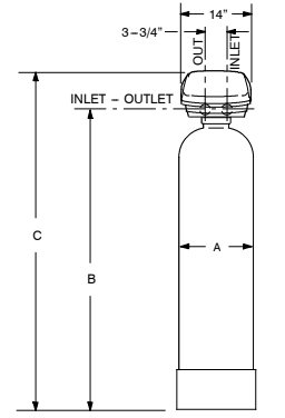
SPECIFICATIONS / DIMENSIONS
| SEDIMENT NSSFSSA 10” APF* NSAPFSSA | NEUTRALIZER NSANSSA 10” APF* NSAPFSSA | TASTE & ODOR NSTOFSSA 10” APF* NSAPFSSA | 12” APF* NSAPFXLA | |
| Type of mineral | Aggregate | Neutralite/Magnesium Oxide | Activated Carbon | * |
| Amount of mineral (cu ft) | 1.0 | 1.0 (4) | 1.0 | 2.0 |
| Amount of gravel base (lbs) | 17 | 17 | 17 | 29 |
| Amount of filter sand (lbs) | 20 — 125 | 20 — 125 | 20 — 125 | 20 — 125 |
| Maximum water temperature (_F) | 120 | 120 | 120 | 120 |
| Minimum inlet water flow (gal/hour) | 270 | 270 | 270 | 270 |
| Service flow rate (gal/min) (1) | 10 | 12 | 14(9) | — — |
| Backwash flow rate (gal/min)(2) | 5 | 5 | 5 | 7 |
| Inlet —outlet pipe size (inch)(3) | 1 | 1 | 1 | 1 |
| Filtering micron rating | 20 | — — | — — | — — |
| Supply water pH limits | — — | 6.0 — 6.8(5) | — — | — — |
| Capacity (gal) | 8,600(6) | 15,500(7) | 45,000(8) | — — |
(1)at 10 psi maximum pressure drop(2) at 35 psi inlet pressure(3) Valve inlet, outlet and sweat copper tubes provided are 1”. Recommended supply pipe size 3/4” to 1 —1/4”. (4) 75% neutralite, 25% magnesium oxide (5) The filter may help to neutralize supply water having lower pH, depending on geographic location. (6) tested with 5.0 NTU (AC coarse test dust) (7) tested with 6.0 — 6.2 pH(8) tested with 3.0 ppm chlorine(9) Taste & Odor Filter.
- APF models do not include mineral, gravel and sand. It is the choice of your contractor depending on the type of filtering required for your water supply.
| ALL 10” DIAMETER FILTERS | 12” DIAMETER APF | |
| A | 10” | 12″ |
| B | 49–3/4” | 55–1/2” |
| C | 58–1/8” | 64–1/4” |
| Nominal Mineral Tank Size | 10” diameter by 47” high | 12” diameter by 54” high |
BEFORE STARTING INSTALLATION
WHERE TO INSTALL THE FILTER
- Place the filter as close as possible to the pressure tank (well system) or water meter (city water).
- Place the filter as close as possible to a floor drain, or other acceptable drain point (laundry tub, sump, standpipe, etc.). The drain point must be able to discharge the backwash flow rates .
- Connect the filter to the main water supply pipe BEFORE or AHEAD OF the water heater. DO NOT RUN HOT WATER THROUGH THE FILTER. Temperature of water passing through the filter must be less than 120_F (49_C).
- Keep outside faucets on unfiltered water to conserve filtering capacity.
- Do not install the filter in a place where it could freeze. Damage caused by freezing is not covered by the warranty.
- Put the filter in a place water damage is least likely to occur if a leak develops. The manufacturer will not repair or pay for water damage.
- A 120 volt electric outlet, to plug the included transformer into, is needed within 10 feet of the filter. The transformer has an attached 10 foot power cable. Be sure the electric outlet and transformer are in an inside location, to protect from wet weather.
- If installing in an outside location, you must take the steps necessary to assure the filter, installation plumbing, wiring, etc., are as well protected from the elements, contamination, vandalism, etc., as when installed indoors.
- Keep the filter out of direct sunlight. The sun’s heat may soften and distort plastic parts.
TOOLS, PIPE and FITTINGS, OTHER MATERIALS YOU WILL NEED
- Plastic inlet and outlet fittings included with the filter allow water flow equivalent to 1” (nominal) pipe. To maintain full valve flow, 1” pipes to and from the filter fittings are recommended. Some local codes require a minimum of 1” pipe size. Do not reduce the pipes to less than 3/4” size.
- Use copper, brass, or galvanized pipe and fittings. Some codes may also allow CPVC plastic pipe.
- ALWAYS install the included bypass valve, or 3 shut-off valves. Bypass valves let you turn off water to the filter for repairs if needed, but still have water in the house pipes.
- Drain hose (5/8” inside diameter minimum), with a garden hose connection on one end, is needed for the valve drain.
- If a rigid valve drain is needed, to comply with plumbing codes, you can buy the parts needed to connect a 1/2 in. copper tubing drain.
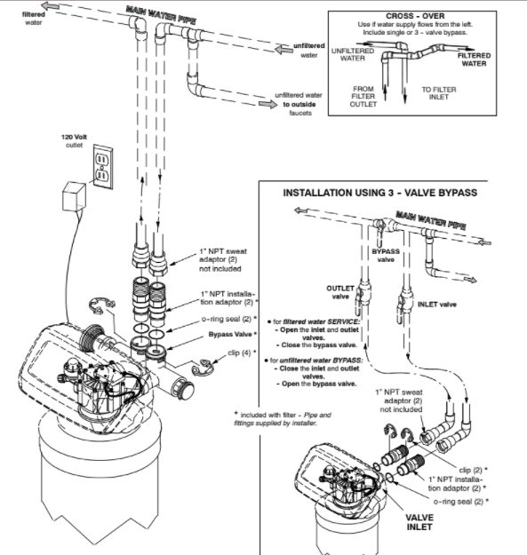
PLAN HOW YOU WILL INSTALL THE FILTER
You must first decide how to run in and out pipes to the filter. Look at the house main water pipe at the point where you will connect the filter. Is the pipe soldered copper, glued plastic, or threaded brass/galvanized? What is the pipe size?
Now look at the typical installation. Use it as a guide when planning your particular installation. Be sure to direct raw, unfiltered water to the filter valve inlet fitting. The valve is marked IN and OUT.
TYPICAL SOLDERED COPPER or CPVC INSTALLATIONS
INSTALLATION STEPS
IMPORTANT SANITIZING PROCEDURES: Care is taken at the factory to keep your water filter clean and sanitary. Materials used to make the filter will not
infect or contaminate your water supply, and will not cause bacteria to form or grow. However, during shipping, storage, installing and operating, bacteria
could get into the filter. For this reason, sanitizing as follows is suggested when installing.
A. Pour about 1 ounce of the following disinfectant into the valve inlet fitting.
a. calcium hypochlorite, available in granular or tablet form, under trade names such as Perchloron or HTH — OR —
b. common 5.25% household bleach (Clorox, Linco, Bo Peep, White Sail, Eagle, etc., brands)
B. Complete the santizing procedures in steps 6 and 9,
NOTE: Sanitizing is recommended by the Water Quality
Association for disinfecting. On some water supplies, they suggest periodic sanitizing.
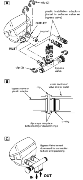
1.INSTALL BYPASS VALVE and/or PLASTIC INSTALLATION ADAPTORS:
Push the bypass valve, with lubricated o —ring seals in place, into the valve inlet and outlet ports…Figures 1A and 1C.
— AND/OR —
Slide plastic installation adaptors, with lubricated o —ring seals in place, into the valve inlet and outlet ports…Figure 1A.
Note: Be sure the support is in place in the valve outlet, as shown in Figure 1A.
Snap the two large plastic clips in place, from the top, down…Figures 1A and 1B. Be sure they snap into place. Pull on the installation adaptors, or bypass valve, to make sure they are held securely in place.
2.MOVE THE FILTER ASSEMBLY INTO INSTALLATION POSITION:
Be sure the installation surface is level and smooth. If needed, place the tank on a section of 3/4” thick (min.) plywood. Then, place shims under the plywood as needed to level the filter.
3.PLUMB IN AND OUT PIPES TO AND FROM FILTER:
CAUTIONS: Observe all of the following cautions while you connect inlet and outlet plumbing.
- Turn off the house water supply valve and open faucets to relieve pressure in the pipes.
- BE SURE RAW, UNFILTERED WATER IS DIRECTED TO THE VALVE INLET PORT.
- Be sure to use bypass valve(s).
- If making a soldered copper installation, do all sweat soldering before connecting pipes to the filter fittings. Torch heat will damage plastic parts.
- When turning threaded pipe fittings onto plastic fittings, use care not to cross —thread.
- Use pipe joint compound on all external pipe threads.
- Support inlet and outlet plumbing in some manner (use pipe hangers) to keep the weight off of the valve fittings.
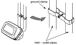
4.INSTALL GROUND CLAMP (IF NEEDED):
NOTE: A 3 valve bypass system maintains ground continuity.
- To maintain electrical ground continuity in the house cold water piping, install the included ground clamp as shown. Be sure the pipes are clean, under the clamps, to assure good contact.
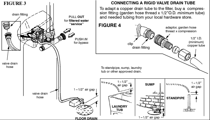
5.CONNECT AND RUN THE VALVE DRAIN HOSE:
- Take a length of 5/8” inside diameter garden hose and attach to the valve drain fitting.
- Locate the other end of the hose at a suitable drain point…floor drain, sump, laundry tub, etc. Check and comply with local codes.
IMPORTANT: Use high quality, thick wall hose that will not easily kink or collapse. The filter will not backwash properly if water cannot exit this hose during regenerations.
Refer to Figure 4 if codes require a rigid pipe drain run.
- Tie or wire the hose in place at the drain point. Water pressure will cause it to whip during the backwash and fast rinse cycles of regeneration. Also provide an air gap of at least 1 —1/2” between the end of the hose and the drain point. An air gap prevents possible siphoning of sewer water, into the filter, if the sewer should back up.
- If raising the drain hose overhead is required to get to the drain point, do not raise higher than 8’ above the floor. Elevating the hose may cause a back pressure that could reduce backwash flow and proper mineral bed cleaning.
6.FLUSH PIPES, CIRCULATE DISINFECTANT, EXPEL AIR FROM FILTER, AND TEST YOUR INSTALLATION FOR WATER LEAKS:
CAUTION: To avoid water or air pressure damage to filter inner parts, be sure to do the following steps exactly as listed.
A. Fully open two cold, filtered water faucets nearby the filter.
B. Place bypass valve(s) in ‘‘bypass’’ position. On a single valve, slide the stem inward to BY-PASS…see page 8. On a 3 valve system, close the inlet and outlet valves, and open the bypass valve.
C. Fully open the house main water pipe shutoff valve. Observe a steady flow from both opened faucets.
D. Place bypass valve(s) in ‘‘service”, EXACTLY as follows. KEEP FILTERED WATER FAUCETS OPEN.
- SINGLE BYPASS VALVE: SLOWLY, pull the valve stem outward to ‘‘service’’, pausing several times to allow the filter to pressurize slowly.
- 3 VALVE BYPASS: Fully close the bypass valve and open the outlet valve. SLOWLY, open the inlet valve, pausing several times to allow the filter to pressurize slowly. The sanitizing bleach also circulates through the filter.
E. After about three minutes, open a HOT water faucet for one minute, or until all air is expelled, then close.
F. Close both cold water faucets.
G. Check your plumbing work for leaks and fix right away, if any are found. Be sure to observe previous caution notes.
H. Turn on the gas or electric supply to the water heater. Light the pilot, if applicable.
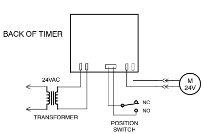
7.CONNECT TO ELECTRICAL POWER:
The filter works on 24 volt, 60 Hz electric power. The included transformer changes standard 120 volt AC house power to 24 volts. Plug the transformer into a 120 volt outlet only. Be sure the outlet is always ‘‘live’’ so it can not be switched off by mistake. Plug the transformer into the electrical outlet.
8.PROGRAM THE TIMER
9.About 20 minutes after completing step 6, use the RECHARGE NOW feature, on the timer, to start an immediate backwash. Any remaining sanitizing
bleach is drawn through the filter and discharged to the drain. The backwash and following fast rinse is over in about 40 minutes. Then, filtered water is
available for your use.
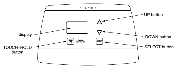
PROGRAMMING THE TIMER
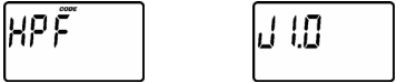
TIMER SETTINGS REQUIRED…upon installation, and after an extended power outage (see Power Outage Memory).
When the transformer is plugged into the electrical outlet, the model code and a test number (example: J1.0), begins to flash in the faceplate display. Then, 12:00 PM and PRESENT TIME begins to flash. Program the timer as follows.
SET PRESENT TIME OF DAY
If the words PRESENT TIME do not show in the display, press the SELECT button until they do.
Press the UP or DOWN buttons to set the present time. Up moves the display ahead; down moves the time backward. Be sure AM or PM, is correct.

Press buttons and quickly release to slowly advance the display. Hold for fast advance. This procedure applies for all following settings.
Press the SELECT button to set present time and advance to the next set up screen.
SET DAYS TO RECHARGE
The default setting is 3 days. This means the filter will recharge every 3 days. If a change is needed, use the UP or DOWN buttons to set from 1 to 99 days between recharges.

| Iron (parts per million) | ||||
| Number of People | 1 — 2 | 3 — 4 | 5 — 7 | 8 — 20 |
| 1 | 4 days | 3 days | 2 days | 1 day |
| 2 | 4 days | 3 days | 2 days | 1 day |
| 3 | 4 days | 3 days | 1 day | 1 day |
| 4 | 3 days | 2 days | 1 day | 1 day |
| 5 | 3 days | 2 days | 1 day | 1 day |
| 6 | 2 days | 1 day | 1 day | 1 day |
| 7 | 2 days | 1 day | 1 day | 1 day |
NOTE: If the water supply has high turbidity (sand, silt, sediments, etc.) set the filter to regenerate more often than the table above shows. Carbon and neutralizing filters may only need to backwash once a week, depending on application.
Press the SELECT button to set and advance to the next set up screen.
SET RECHARGE TIME
The default setting is 12:00 AM. This is a good time if you have a water softener or another filter installed, the recharge time should be offset to assure adequate water flow and pressure. For example, set the filter to start backwash at 12:00 AM, or 4:00 AM, if the water softener is set to begin recharge at 2:00 AM.
If a change is needed, use the UP or DOWN buttons to set time.

Press the SELECT button to set and return to the normal run display.
THE INSTALLATION AND PROGRAMMING STEPS ARE COMPLETE
NOTE: After you have completed all preceding instructions, your house water supply is filtered immediately. However, your water heater is filled with unfiltered water and, as hot water is used, it will refill with filtered water. When all the water is replaced in the water heater, all water will be filtered. If you want totally filtered water immediately, drain the water heater after the backwash initiated on page 9 is over (no water running from filter drain hose). Drain until the water runs cold. If you do drain the water heater, use extreme care as the hot water could cause severe burns.
FACEPLATE TIMER FEATURES, SETTINGS AND SERVICE
NORMAL OPERATION, TIMER DISPLAYS
During normal operation, the present time of day, and AM or PM, show in the time display area. When a regeneration begins, RECHARGE NOW

starts to flash in the display, along with the present time of day. RECHARGE NOW flashes until the regeneration is over.

feature: RECHARGE NOW
For times you expect to use more water than usual, use the RECHARGE NOW control. Press the Touch —Hold button until RECHARGE NOW begins to flash in the time display.

A regeneration begins immediately. The filter begins to filter your water again in about 2 hours.
NOTE: Avoid using HOT water during the regeneration, because the water heater will refill with unfiltered water.
feature: VACATION CONTROL
Before going on vacation, or other long absence, press (do not hold in) the Touch —Hold button so VAC starts to flash in the display. The timer continues to keep time, but regenerations will not occur and waste water.

When you return, press the Touch —Hold button again to return the filter to service, and the present time in the display. REMEMBER TO DO THIS, or the
filter will not regenerate until you do.
NOTE: To shut off the water supply to the filter, use the plumbing bypass valve(s).
feature: POWER OUTAGE MEMORY
If electrical power to the timer is interrupted, the “memory” built into timer circuitry keeps all settings for 6 hours (minimum) or more. The display is blank
and the filter will not regenerate. When electrical power comes on, one of two things will happen.
- The present time of day will show, meaning the timer memory has kept all time settings.
NOTE: If the filter was regenerating when power was lost, it will now finish the cycle.
- The display will show a time, but it will be flashing. The timer memory did not keep the time of day and it may need to be reset (page 10). The display returns to a flashing time, then begins to keep time again. If you do not reset the time of day, the filter will regenerate based on the days to recharge, however, regenerations will most likely be at the wrong time of day.
NOTE: The flashing display is to remind you to reset the timer.
If the filter was regenerating when power was lost, the valve will return to service position without finishing the cycle. Use RECHARGE NOW (see above) to start another cycle if needed.
feature: ERROR CODES
An error code could appear in the faceplate display if a problem occurs in the filter. If you see an error code, for example Err03,

instead of the present time of day, please call your local dealer for service, or see your warranty.
service: REGENERATION CYCLE TIME ADJUSTMENTS
The default settings for backwash (25 minutes) and fast rinse (5 minutes) cycles of regeneration are factory set for maximum performance of the filter. Use the following procedures to check for correct cycle times, or to change if desired. However, only trained technicians should change the time settings.
service: ADJUSTABLE BACKWASH TIME
Press and hold the Select button until the display shows “000 — —”, then press the Select button three times to advance to the Backwash time adjust screen.

Using the Up or Down buttons adjust the backwash time from 0 minutes to 60 minutes.

service: ADJUSTABLE FAST RINSE TIME
Press and hold the Select button until the display shows “000 — —”, then press the Select button four times to advance to the Fast Rinse time adjust screen.
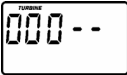
Using the Up or Down buttons adjust the Fast Rinse time from 0 minutes to 60 minutes.

service: TIMER / FILTER, SERVICE CHECKOUT PROCEDURE
If you are not getting filtered water, use the procedures below to find the problem. First, make the following visual checks.
- Is there electrical power to the outlet the filter transformer is plugged into?
- Is the plumbing bypass valve, or valves, directing water for filtered water service ?
- Is the valve drain hose open to the drain, not elevated too high, and unobstructed?
If you do not find a problem with the visual checks, continue below.
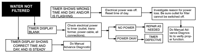
service: MANUAL ADVANCE DIAGNOSTIC
Use the following procedures to advance the filter valve through the regeneration cycles to check operation.
Remove the top cover to observe cam and switch operation during valve rotation.
DISPLAY MUST SHOW TIME AND DAY
- Press and hold the Touch —Hold button for 3 seconds until RECHARGE NOW flashes in the display and the filter moves into the backwash cycle.

If the motor does not run, check the motor and all wiring connections.
Look for a fast flow of water from the drain hose (see specifications).
An obstructed flow indicates a plugged top distributor, backwash flow plug, or drain hose.
NOTE: Be sure household water pressure (well system) is maintained at a minimum of 20 psi. Adjust the pump switch upward, if needed.
- Press the Touch–Hold button to move the filter into fast rinse. Again, look for a drain flow rate about the same as backwash.
- To return the filter to service, press the Touch Hold button once.
NOTE: While in manual advance, the time display will automatically return to the present time if a button is not pressed within 4 minutes.
OTHER SERVICE
UNFILTERED WATER BYPASS (unfiltered water “bleeds” into filtered water supply.
- Missing or defective o–ring(s) at resin tank to valve connection.
- Defective rotor disc, seal or wave washer.
WATER LEAKS FROM DRAIN HOSE (during service)
- Defective rotor disc, seal, or wave washer.
- Defective o–ring on disc shaft.
GENERAL FILTER INFORMATION
SEDIMENT FILTER
A sediment filter removes sand, dirt, clay, silt, and fine organic matter from water. You can see sediment in water by filling a clear drinking glass and holding it up to a light. The sediment particles are either suspended in the water, or settled to the bottom of the glass.
The mineral bed in the sediment filter is a ‘‘filter aggregate’’ material. The bed traps and holds the sediments as water flows through it. When properly maintained, the mineral can last indefinitely.
WATER NEUTRALIZING FILTER
All water, when chemically analyzed, is either acid, neutral, or base (alkaline). To measure this, the water is given a pH value between 0 and 14. Water having a pH from 0 to 6.9 is acid. A pH of 7 is neutral. Above 7, the water is alkaline.
Acid water, although sometimes clear in appearance, shortens the life of iron pipe and corrodes copper or brass pipe and fittings. It causes green or blue stains on plumbing fixtures, and may etch porcelain enamel over a period of time.
An acid neutralizer filter is used to treat water with a pH of 6.0 to 6.8. The filter is filled with a bed of neutralite/magnesium oxide mineral. As acid water passes through the filter, some of the mineral dissolves to raise the pH and neutralize the acid. Because the mineral does dissolve, the filter needs to be refilled. How often depends on the amount of acidity, and how much water is used. See page 17 to determine when refilling is needed.
TASTE & ODOR FILTER
Taste & odor filters remove most tastes, odors and certain organic colors from water. Bad tastes and odors are due to a variety of causes (chlorine, petroleum, tannins, etc.). Activated carbon mineral, used in this filter, has a high capacity for adsorbing these impurities.
The activated carbon mineral bed usually lasts for about one year before it’s exhausted. High amounts of tastes and odors, and/or higher water usages may shorten this time. Activated carbon can’t be regenerated and must be replaced when exhausted.
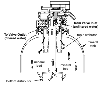
HOW THE SEDIMENT, NEUTRALIZING, AND TASTE & ODOR FILTERS WORK
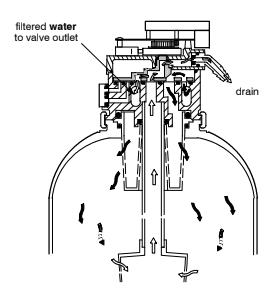
FILTERED WATER ”SERVICE”: Unfiltered water enters the valve inlet port. Internal valve porting routes the water down and out the top distributor and into the mineral tank. As water flows downward through the mineral bed, sediment or taste and odor is removed, or mineral is dissolved to neutralize acid. Filtered water enters the bottom distributor, goes up the riser pipe and to the valve outlet port. Filtered water is directed to a house faucet when opened.
In time, the filter needs cleaning to remove sediments, dirt, iron, etc., and to mix the mineral bed to remove water channels. This cleaning is done in two
stages or cycles, backwash and fast rinse. The cleaning cycle is started automatically by the timer.
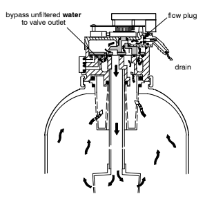
BACKWASH: The timer energizes the valve motor which positions internal valve porting for backwash. Water flow is reversed upward through the filter, and
at a fast rate to flush the sediments, dirt, iron, etc., from the bed. The valve drain port is also opened to allow discharge of the cleaned materials to the drain
point. The accelerated flow lifts and expands the mineral bed for maximum cleaning. The filter backwashes for 25 minutes, or as otherwise set.
During the backwash cycle, valve porting provides bypass unfiltered supply water to house faucets for emergency needs. However, you should avoid the use of hot water because the water heater will refill with the unfiltered water. In most households, water is not in use since the cleaning cycles occur during early morning hours (at timer default values).
FAST RINSE: Backwash is followed by the fast rinse cycle. Valve porting is changed again to return a downward flow of water through the mineral bed. As
in backwash, flow is at a fast rate to flush unfiltered water and remaining sediments to the drain, and to pack the mineral bed in preparation for return to
‘‘service’’.
The timer default fast rinse time is 5 minutes.
The filters require a minimum of care. A backwash at regular intervals will keep the filter mineral bed clean and operating at top efficiency. Eventually, a neutralizer filter will require a refill of mineral because it does dissolve away. The activated carbon in a taste & odor filter, will need to be replaced after it has exhausted it’s ability to adsorb. Be sure to protect your filter from freezing temperatures.
PROTECT THE FILTER FROM FREEZING
If the filter is installed where it could freeze (summer cabin, lake home, etc.), you must drain all water from it to prevent possible damage caused by freezing. To drain the filter…
- Close the shut-off valve on the house main water pipe, near the water meter or pressure tank.
- Open a filtered water faucet to vent pressure in the filter.
- Refer to Figure 3 . Move the stem in a single bypass valve to bypass. Close the inlet and outlet valve in a 3 valve bypass system, and open the bypass valve. If you want water in the house pipes again, reopen the shut-off valve on the main water pipe.
- Unplug the transformer at the wall outlet. Refer to the parts drawings . when doing the following steps.
- Pull the clip holding the drain fitting to the valve and remove the fitting with the drain hose attached. Do not lose the flow plug assembly located in the drain fitting.
- Carefully remove the large holding clips at the filter inlet and outlet (Figure 1,). Separate the filter from the copper tubes, or from the bypass valve.
- Move the filter close to the drain. SLOWLY and CAREFULLY (the filter is heavy), tip the filter over so the valve inlet and outlet are over the drain. Do not
allow the filter’s weight to rest on the inlet and outlet fittings or they will break. Tip the bottom of the filter up a few inches and hold until all water has
drained.
Notes:
Leave the filter laying like this until you are ready to use it again. Plug the inlet and outlet with rags to keep dirt, bugs, etc. out. Sanitizing is suggested when putting the filter back into service.
ADDING MINERAL TO THE NEUTRALIZING FILTER
The neutralite/magnesium oxide mineral slowly dissolves to neutralize acid in the water. If the filter is not serviced, all of the mineral would dissolve. How fast
it dissolves depends on the pH of the water, how much water is used, and other water conditions. Because of the variables, it is difficult to determine exactly when to add more mineral. When you have had the filter for a period of time, experience will tell you when to add more mineral. You can use the instructions following step 7,as a guide to determine when to refill the next time.
ADDING MINERAL
Refill the filter with mineral the first time about 6 months after installation. See step 7, to determine the next time to refill.
- Press the Touch —Hold button until RECHARGE NOW begins to flash in the time display.
- Wait until water begins to flow from the valve drain hose. Then, place the bypass valve(s) in bypass position. , and to Figure 3 .
Important: To relieve pressure in the tank, be sure to do steps 1 and 2 as instructed. - Unplug the transformer at the wall outlet.
- Carefully remove the clips at the filter valve inlet and outlet. Then, separate the filter from the copper tubes, or from the bypass valve (Figure 1).
- Remove the two clamp retainers and two clamp sections that hold the valve to the tank. Lift the valve assembly up and off the tank.
- Remove three o —ring seals and the top distributor from the tank. Inspect the o —rings to be sure they are reusable (see repair parts pages). Set the parts safely aside so they won’t be lost or broken.
- To make room in the tank for new mineral, use a hose to siphon water out. Run the hose about 36” down the inside of the bottom distributor. Be careful
not to damage the top edge of the tube.
DETERMINE MINERAL ADDING FREQUENCY
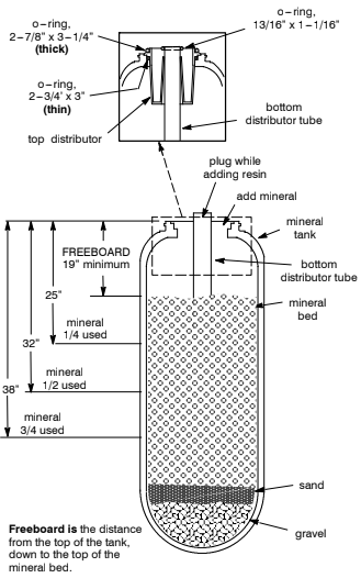
At this time, take a yard stick or tape rule and measure down to the top of the mineral bed. Use a flashlight so you can visually see the top of the bed. Measure inches as shown in Figure 5.
If the measurement is 32” or less, over half of the mineral bed remains. You could wait for 9 —10 months before refilling the next time (assuming water usage remains about the same).
If the measurement is 38” or more, less than 1/4 of the bed remains. It may be better to add mineral more often than every 6 months.
- Plug the end of the bottom distributor tube with a rag. Then, use a large neck funnel to add new mineral into the tank.
CAUTIONS:
Do not pour mineral into the bottom distributor tube. Do not overfill the tank. Freeboard area (Figure 5) is needed for proper backwash cleaning of the mineral bed.
- Use water to flush the tank top opening. It must be clean for good o —ring sealing surfaces.
- Be sure the three o —ring seals are lubricated (use silicone grease or vaseline). Then, referring to the inset drawing in Figure 5, place in position along with the top distributor.
- Carefully, lower the valve assembly onto the tank adaptor. Install the clamps and retainers, being sure they are securely fastened.
- Do step 1 .
- Do steps 6 and 7 . The filter will complete the backwash you started in step 1.
REPLACING MINERAL IN THE TASTE & ODOR FILTER
The activated carbon mineral adsorbs tastes and/or odors in the water supply. How long it lasts depends on how much water is used, and other conditions.
Average life of the mineral is about one year. When tastes and/or odors return in your filtered water, mineral bed replacement is needed.
MINERAL REPLACEMENT
- Press the Touch —Hold button until RECHARGE NOW begins to flash in the time display.
- Wait until water begins to flow from the valve drain hose. Then, place the bypass valve(s) in bypass position. Refer to page 6, and to Figure 3.
Important: To relieve pressure in the tank, be sure to do steps 1 and 2 as instructed. - Unplug the transformer at the wall outlet.
- Carefully remove the clips at the filter valve inlet and outlet. Then, separate the filter from the copper tubes, or from the bypass valve (Figure 1,.
- Remove the two clamp retainers and two clamp sections that hold the valve to the tank. Lift the valve assembly up and off the tank.
- Remove three o —ring seals and the top distributor from the tank. Inspect the o —rings to be sure they are reusable (see repair parts pages). Set the parts safely aside so they won’t be lost or broken.
CAUTION: Handle the tank carefully when doing the following step. Do not attempt to lift the tank. Wet carbon is very heavy. - At a floor drain, carefully tip the tank over to empty the contents. Catch the carbon in a burlap sack or other suitable container. Remove the bottom distributor when you are able to do so.
- Flush the inside of the tank with fresh water to thoroughly clean.
9.Stand the tank upright and replace the bottom distributor. Plug the end of the bottom distributor tube with a rag.
- Use a large neck funnel to add the new bed. First, add 17 lbs of gravel, followed by 10 lbs of filter sand. Finally, being sure the bottom distributor is
centered, add 1 cu ft of activated carbon mineral into the tank. Use water sparingly to assist the flow of mineral through the funnel. - Use water to flush the tank top opening. It must be clean for good o —ring sealing surfaces.
- Be sure the three o —ring seals are lubricated (use silicone grease or vaseline). Then, referring to the inset drawing in Figure 5, place in position along
with the top distributor. - Carefully, lower the valve assembly onto the tank adaptor. Install the clamps and retainers, being sure they are securely fastened.
- Do step 1.
- Do steps 6 and 7 . The filter will complete the backwash you started in step on page
NOTE: Backwashing removes carbon ‘‘fines’’ (too small or fine particles) from the new mineral. If the filtered water still contains fines, after the backwash, repeat step 1 to initiate another backwash, or open faucets and let the water run until clear.
CHECKLIST BEFORE YOU CALL FOR SERVICE
| PROBLEM | CAUSE | CORRECTION |
| FILTER WILL NOT BACKWASH | Manual plumbing bypass valve(s) in bypass position | Refer to Figure 3, and position for filtered water ‘‘service’’. |
| Transformer unplugged at wall outlet, power cable disconnected from back of circuit board, fuse blown/circuit breaker popped, circuit switched off | Check for loss of power and correct as needed. Reset the timer and use the RECHARGE NOW feature. | |
| Timer set for vacation (VAC) | Press the Touch —Hold button once to return the filter to ‘‘service’’, | |
| Timer programmed for backwash, but time too short | set. | |
| Error code shows in timer display | ||
| Backwash flow control, drain hose restricted or plugged | Check drain hose. Remove drain elbow on filter valve to check flow control. See page 22 to check for correct assembly and orientation. | |
| LOW WATER PRESSURE AT HOUSE FAUCETS | Well pump pressure switch set too low | Adjust to a minimum of 20 psi. |
| Backwash needed more often to keep filter mineral clean | ||
| FILTERED WATER CONTAINS SEDIMENT, IRON, DIRT, ETC. | See all conditions above | |
| NEUTRALIZER FILTER ONLY: FILTERED WATER IS ACID OR PARTLY ACID NOTE: Trace plumbing to be sure faucet is connected to with filtered water. | Manual plumbing bypass valve(s) in bypass position | see above |
| Filter low on neutralite mineral | Add new mineral, | |
| TASTE & ODOR FILTER ONLY: FILTERED WATER HAS BAD TASTE AND/ OR ODOR NOTE: Trace plumbing to be sure faucet is connected to with filtered water. | Manual plumbing bypass valve(s) in bypass position | see above |
| Activated carbon mineral exhausted | Replace mineral bed, |
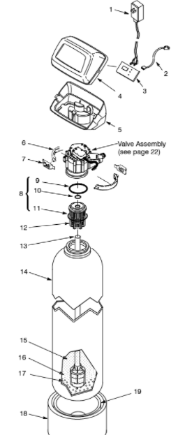
REPAIR PARTS — FILTER ASSEMBLY
| KEY NO. | PART NO. | DESCRIPTION |
| 1 | 7275907 | Transformer, 24V — 10VA |
| 2 | 7259927 | Wire Harness |
| 3 | 7286699 | Repl. Timer (PWA) |
| 4 | 7260554 | Cover (order req’d decal below) |
| — | 7285279 | Decal, Cover |
| 5 | 7189449 | Bottom Cover |
| 6 | 7176292 | Clamp Section (2) |
| 7 | 7088033 | Clamp Retainer (2) |
| 8 | 7112963 | O — ring Kit (includes key no. 9, 10 & 11) |
| 9 | — — | O — ring, 2 —7/8” x 3 —1/4” |
| 10 | — — | O — ring, 13/16” x 1 —1/16” |
| 11 | — — | O — ring, 2 —3/4” x 3” |
| 12 | 7088855 | Top Distributor |
| 13 | 7105047 | Repl. Distributor |
| 14 | 7092202 | Mineral Tank, 10” |
| 7113074 | Mineral Tank, 12” | |
| 15 | 0505647 | Mineral, 1 cu ft — Sediment Filter |
| 7161912 | Mineral, 1/2 cu ft bag — Neutralizer | |
| 3424509 | Mineral, 1 cu ft — Taste & Odor Filt. | |
| 16 | 0501783 | Filter Sand, 10 lbs |
| 17 | 7124415 | Gravel, 17 lbs |
| 18 | 7302039 | Tank Foot, 10” tanks |
| 7124481 | Tank Foot, 12” tanks | |
| 19 | 7125241 | Foam Base, 12” tanks |
READ ALSO: Morton Water Softener Model M45C User’s Manual
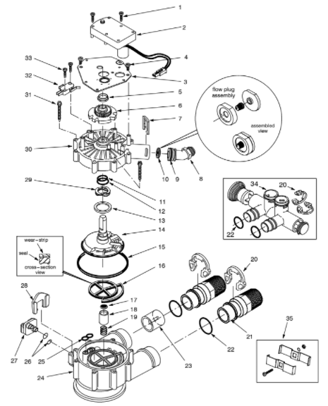
VALVE ASSEMBLY
| KEY NO. | PART NO. | DESCRIPTION |
| 1 | 7224087 | Screw, #8-32 x 1” (2 req.) |
| 2 | 7286039 | Motor (incl. 2 ea. of Key No. 1) |
| 3 | 7231393 | Motor Plate |
| 4 | 0900857 | Screw, #6-20 x 3/8 (3 req.) |
| 5 | 7171250 | Bearing |
| 6 | 7283489 | Cam and Gear |
| 7 | 7169180 | Clip (Drain) |
| 8 | 7172793 | Drain Hose Adaptor |
| 9 | 7170288 | O-ring, 15/16 x 1 —3/16 |
| 10 | 7178189 | Flow Plug, 5 gpm (10” dia. APF) |
| 7178202 | Flow Plug, 7 gpm (12” dia. APF) | |
| 11 | — | O-ring, 5/8 x 13/16 |
| 12 | — | O-ring, 1 —1/8 x 1 —1/2 |
| 13 | 7174313 | Bearing, Wave Washer |
| 14 | 7185500 | Rotor & Disc |
| 15 | — | O-ring, 4 —1/2 x 4 —7/8 |
| 16 | — | Rotor Seal |
| 17 | — | Seal |
| 18 | 7171187 | Plug (Drain Seal) |
| 19 | 7129889 | Spring |
| 20 | 7089306 | Clip (4 req.) |
| KEY NO. | PART NO. | DESCRIPTION |
| 21 | 7271204 | Installation Adaptor, 1” (2 req.) |
| 22 | 7170262 | O — ring, 1 —1/8 x 1 —3/8 (4 req.) |
| 23 | 7078240 | Support |
| 24 | 7171145 | Valve Body |
| 25 | — | Seal |
| 26 | 7170319 | O — ring, 1/4 x 3/8 (2 req.) |
| 27 | 7100940 | Plug |
| 28 | 7081201 | Retainer |
| 29 | 7175199 | Wave Washer |
| 30 | 7171161 | Valve Cover |
| 31 | 7172997 | Screw, #10 x 2 —5/8 (8 req.) |
| 32 | 7305150 | Switch |
| 33 | 7140738 | Screw, #4-24 x 3/4 (2 req.) |
| 34 | 7214317 | Bypass Valve (Includes following parts) |
| — | 7172882 | Stem |
| — | 7173016 | O — ring, 1.109 I.D. x 1.387 O.D. (4) |
| — | 7175238 | C — ring |
| 35 | 7248706 | Ground Clamp Asm. |
| | 7185487 | Seal Kit (incl. Key Nos. 11, 12, 15, 16, 17 and 25) |
not illustrated.
You can download the PDF version of the NORTH STAR AUTOMATIC WATER FILTRATION USER’S MANUAL here.