IF YOU HAVE QUESTIONS WHEN INSTALLING, OPERATING AND MAINTAINING YOUR CONDITIONER, OR WHEN SETTING THE TIMER
CALL TOLL FREE: 1 — 800 — 972 — 0135 IN CANADA CALL: 1 — 800 — 796 — 6784
Systems tested and certified by NSF International against NSF/ANSI Standard 44 for hardness reduction and efficiency, and certified to NSF/ANSI Standard 372.
Systems tested and certified by the Water Quality Association against CSA B483.1.
WATER CONDITIONER WARRANTY
Warrantor: North Star Water Conditioning, 1890 Woodlane Drive, Woodbury, MN, 55125 Warrantor guarantees, to the original owner, that:
One Year Full Warranty:
- For a period of one (1) year from the date of purchase, all parts will be free of defects in materials and workmanship, and will perform their normal functions.
- For a period of one (1) year from the date of purchase, labor to repair or replace any part deemed to be defective in materials and workman-ship, will be provided at no additional cost.
Limited Warranties:
- For a period of ten (10) years from from the date of purchase, the salt tank and fiberglass mineral tank will not rust, corrode, leak, burst, or in any other manner, fail to perform their proper functions.
- For a period of three (3) years from the date of purchase, the electronic control board and valve body will be free of defects in materials and workmanship, and will perform their normal functions.
If, during such respective period, a part proves to be defective, Warrantor will ship a replacement part, directly to your home, without charge. After the first year, labor necessary to maintain this product is not covered by the product warranty.
General Conditions
Damage to any part of this water conditioner because of misuse, misapplication, neglect, alteration, accident, installation or operation contrary to our printed instructions, or damage caused by any unusual force of nature such as, but not limited to, freezing, flood, hurricane, tornado, or earthquake is not covered by this warranty. In all such cases, regular parts and service charges will apply.
We assume no warranty liability in connection with this water conditioner other than specified herein. This warranty is in lieu of all other warranties, expressed or implied, including warranties of fitness for a particular purpose. We do not authorize any person or representative to assume for us any other obligations on the sale of this water conditioner.
Should a defect or malfunction occur, contact your contractor. If you are unable to contact your contractor, return the part, freight prepaid, directly
to the factory at the address below. Enclose with the part a full description of the problem, with your name, full address, date purchased, model
and serial numbers, and selling contractor’s name and address. We will repair or replace the part and return it to you at no cost if our repair department determines it to be defective under the terms of the warranty.
This warranty gives you specific legal rights and you may have other rights which vary from state to state. This water conditioner is manufactured by North Star Water Conditioning, 1890 Woodlane Drive, Woodbury, MN, 55125; customer information telephone no. 1–800–972–0135.
READ ALSO: Morton Water Softener Model M45C User’s Manual
SAFETY GUIDES
FOLLOW THE INSTALLATION INSTRUCTIONS CAREFULLY. FAILURE TO INSTALL THE SOFTENER PROPERLY VOIDS THE WARRANTY.
BEFORE YOU BEGIN INSTALLATION, READ THIS ENTIRE MANUAL. THEN, OBTAIN ALL THE MATERIALS AND TOOLS YOU WILL NEED TO MAKE THE INSTALLATION.
CHECK LOCAL PLUMBING AND ELECTRICAL CODES. THE INSTALLATION MUST CONFORM TO THEM. CODES IN THE STATE OF MASSACHUSETTS REQUIRE INSTALLATION BY A LICENSED PLUMBER. FOR INSTALLATION, USE PLUMBING CODE 248–CMR OF THE COMMONWEALTH OF MASSACHUSETTS.
USE ONLY LEAD–FREE SOLDER AND FLUX FOR ALL SWEAT–SOLDER CONNECTIONS, AS REQUIRED BY STATE AND FEDERAL CODES.
USE CARE WHEN HANDLING THE SOFTENER. DO NOT TURN UPSIDE DOWN, DROP, OR SET ON SHARP PROTRUSIONS.
DO NOT LOCATE THE SOFTENER WHERE FREEZING TEMPERATURES OCCUR. DO NOT ATTEMPT TO TREAT WATER OVER 120F. FREEZING, OR HOT WATER DAMAGE VOIDS THE WARRANTY.
AVOID INSTALLING IN DIRECT SUNLIGHT. EXCESSIVE SUN HEAT MAY CAUSE DISTORTION OR OTHER DAMAGE TO NON–METALLIC PARTS.
THE SOFTENER REQUIRES A MINIMUM WATER FLOW OF 3 GALLONS PER MINUTE AT THE INLET. MAXIMUM ALLOWABLE INLET WATER PRESSURE IS 125 PSI. IF DAYTIME PRESSURE IS OVER 80 PSI, NIGHTTIME PRESSURE MAY EXCEED THE MAXIMUM. USE A PRESSURE REDUCING VALVE IF NECESSARY. ( ADDING A PRESSURE REDUCING VALVE MAY REDUCE THE FLOW.)
THE SOFTENER WORKS ON 28V DC ELECTRICAL POWER, SUPPLIED BY A DIRECT PLUG–IN POWER SUPPLY (INCLUDED). BE SURE TO USE THE INCLUDED POWER SUPPLY, AND PLUG IT INTO A NOMINAL 120V, 60 Hz HOUSEHOLD OUTLET THAT IS IN A DRY LOCATION ONLY, GROUNDED AND PROPERLY PROTECTED BY A OVERCURRENT DEVICE SUCH AS A CIRCUIT BREAKER OR FUSE.
THIS SOFTENER IS NOT INTENDED TO BE USED FOR TREATING WATER THAT IS MICROBIOLOGICALLY UNSAFE OR OF UNKNOWN QUALITY WITHOUT ADEQUATE DISINFECTION BEFORE OR AFTER THE SOFTENER. EUROPEAN DIRECTIVE 2002/96/EC REQUIRES ALL ELECTRICAL AND ELECTRONIC EQUIPMENT TO BE DISPOSED OF ACCORDING TO WASTE ELECTRICAL AND ELECTRONIC EQUIPMENT (WEEE) REQUIREMENTS.THIS DIRECTIVE OR SIMILAR LAWS ARE IN PLACE NATIONALLY AND CAN VARY FROM REGION TO REGION. PLEASE REFER TO YOUR STATE AND LOCAL LAWS FOR PROPER DISPOSAL OF THIS EQUIPMENT.
UNPACKING / INSPECTION
The softener is shipped in one master carton. The softeners are completely assembled at the factory, except as required at installation.
Be sure to check the entire softener for any shipping damage or parts loss. Also note damage to the shipping cartons. Contact the transportation company for all damage and loss claims. The manufacturer is not responsible for damages in transit.
Small parts, needed to install the softener, are in a parts bag. To avoid loss of the small parts, keep them in the parts bag until you are ready to use them.
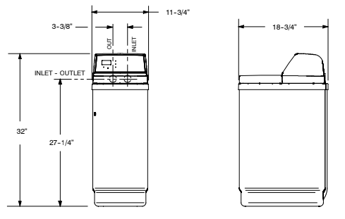
DIMENSIONS
SPECIFICATIONS AND PERFORMANCE CLAIMS
This model is efficiency rated. The efficiency rating is valid only at the minimum salt dose. This softener has a demand initiated regeneration (D.I.R.) feature that complies with specific performance specifications intended to minimize the amount of regenerant brine and water used in its operation.
This softener has a rated softener efficiency of not less than 3,350 grains of total hardness exchange per pound of salt (based on sodium chloride) and shall not deliver more salt than its listed rating or be operated at a sustained maximum service flow rate greater than its listed rating. This softener has been proven to deliver soft water for at least ten continuous minutes at the rated service flow rate. The rated salt efficiency is measured by laboratory tests described in NSF/ANSI Standard 44. These tests represent the maximum possible efficiency that the system can achieve. Operational efficiency is the actual efficiency after the system has been installed. It is typically less than the rated efficiency, due to individual application factors including water hardness, water usage, and other contaminants that reduce a softener’s capacity.
| MODEL NSC15ED | |
| RATED CAPACITY | 7,100 grains with 1.7 lbs. of salt 13,700 grains with 5.4 lbs. of salt 15,700 grains with 8.8 lbs. of salt |
| RATED EFFICIENCY | 4,290 grains/lb. @ 1.7 lbs. of salt |
| WATER USED DURING REGENERATION @ MINIMUM SALT DOSE (gallons) | 2.4 / 1,000 grains |
| TOTAL WATER USED PER REGENERATION @ MAXIMUM SALT DOSE (gallons) | 19.0 |
| AMOUNT OF HIGH CAPACITY RESIN (lbs / cu ft) | 28.6 / 0.55 |
| RESIN TANK NOMINAL SIZE (in., dia x height) | 8 x 25 |
| SERVICE FLOW RATE (gpm) | 5.3 |
| PRESSURE DROP AT RATED SERVICE FLOW (psig) | 7.1 |
| INTERMITTENT FLOW RATE at 15 psi (gpm) | 8.8 |
| WATER SUPPLY MAXIMUM HARDNESS (gpg) | 30 |
| WATER SUPPLY MAX. CLEAR WATER IRON (ppm) | 4 |
| WATER PRESSURE LIMITS (min. / max. psi) | 20 — 125 |
| WATER TEMPERATURE LIMITS (Min./Max. _F) | 40 — 120 |
| WATER SUPPLY MINIMUM FLOW RATE (gpm) | 3 |
| FLOW TO DRAIN DURING RENGENERATION (gpm) | 2.0 |
Intermittent flow rate does not represent the maximum service flow rate used for determining the softeners rated capacity and efficiency. Continuous operation at flow rates greater than the service flow rate may affect capacity and efficiency performance.
Capacity to reduce clear water iron is substantiated by WQA test data. State of Wisconsin requires additional treatment if water
supply contains greater than 5 ppm clear water iron.
Canada working pressure limits: 1.4 — 7.0 kg/cm@. This softener conforms to NSF/ANSI 44 for the specific performance claims as verified and substantiated by test data.
BEFORE STARTING INSTALLATION
WHERE TO INSTALL THE SOFTENER
- Place the softener as close as possible to the pressure tank (well system) or water meter (city water).
- Place the softener as close as possible to a floor drain, or other acceptable drain point (laundry tub, sump, standpipe, etc.).
- Connect the softener to the main water supply pipe BEFORE or AHEAD OF the water heater. DO NOT RUN HOT WATER THROUGH THE
- SOFTENER. Temperature of water passing through the softener must be less than 120_F (49_C). Keep outside faucets on hard water to save soft water and salt.
- Do not install the softener in a place where it could freeze. Damage caused by freezing is not covered by the warranty.
- Put the softener in a place water damage is least likely to occur if a leak develops. The manufacturer will not repair or pay for water damage.
- A 120V, 60 Hz electrical outlet, to plug the included power supply into, is needed near the softener. Be sure the electric outlet and power supply are in an inside location, to protect from wet weather.
- If installing in an outside location, you must take the steps necessary to assure the softener, installation plumbing, wiring, etc., are as well protected from the elements, contamination, vandalism, etc., as when installed indoors.
- Keep the softener out of direct sunlight. The sun’s heat may soften and distort plastic parts.
TOOLS, PIPE and FITTINGS, OTHER MATERIALS YOU WILL NEED
- In and out pipes to the softener must be at least 3/4” size. Some local codes require a minimum of 1” pipe size. To plumb with 1” pipes, buy adaptors to fit the 1” pipe threads on the installation adaptors . You should maintain the same, or larger, pipe size as the water supply pipe, up to the softener inlet and outlet.
- Use copper, brass, or galvanized pipe and fittings. Some codes may also allow CPVC plastic pipe.
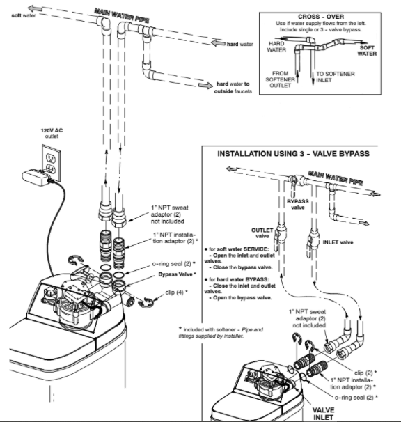
- ALWAYS install a bypass valve or valves. Either use the optional valve (included with some models), or 3 shut-off valves. Bypass valves let you turn off water to the softener for repairs if needed, but still have water in the house pipes.
- Drain hose (3/8” or 7/16” inside diameter) is needed for valve and salt tank drains. You can buy good quality, thick–wall, flexible hose at most hardware stores.
- If a rigid valve drain is needed, to comply with plumbing codes, you can buy the parts needed to connect a 1/2 in. copper tubing drain.
- Nugget or pellet water softener salt is needed to fill the brine tank
PLAN HOW YOU WILL INSTALL THE SOFTENER
You must first decide how to run in and out pipes to the softener. Look at the house main water pipe at the point where you will connect the softener. Is the pipe soldered copper, glued plastic, or threaded galvanized ? What is the pipe size?
Now look at the typical installation illustration . Use it as a guide when planning your particular installation. Be sure to direct raw, hard water to the softener valve inlet fitting. The valve is marked IN and OUT.
TYPICAL SOLDERED COPPER or CPVC INSTALLATIONS
INSTALLATION STEPS
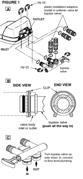
1.INSTALL BYPASS VALVE:
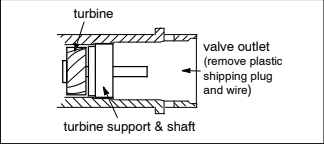
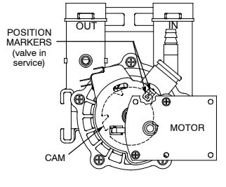
NOTE: Be sure the turbine and support are firmly in place, in the valve outlet. Blow into the valve port and observe the turbine for free rotation.
- Push the bypass valve or installation adaptors (with lubricated o–ring seals) into both ports of the softener valve…Figures 1A and 1C.
- Snap the two large plastic clips in place, from the top, down…Figures 1A and 1B. Be sure they snap into place. Pull on the adaptors, or bypass valve, to make sure they held securely in place.
2.INSTALL THE BRINE TANK OVERFLOW FITTINGS:
- Insert the rubber grommet into the 3/4” diameter hole in the brine tank sidewall.
- Push the barbed end of the hose adaptor elbow into the grommet.
3.MOVE THE SOFTENER ASSEMBLY INTO INSTALLATION POSITION:
- Be sure the installation surface is level and smooth. If needed, place the tank on a section of 3/4” thick (min.) plywood. Then, place shims under the plywood as needed to level the softener.
4.PLUMB IN AND OUT PIPES TO AND FROM SOFTENER:
CAUTIONS: Observe all of the following cautions as you connect inlet and outlet plumbing.
- Turn off the house water supply valve and open faucets to relieve pressure in the pipes.
- BE SURE RAW, HARD WATER IS DIRECTED TO THE VALVE INLET PORT.
- Be sure to use bypass valve(s).
NOTE: CHECK LOCAL PLUMBING AND ELECTRICAL CODES. THE INSTALLATION MUST CONFORM TO THEM. In Massachusetts, plumbing codes of Massachusetts shall be adhered to. Consult with your licensed plumber.
- If making a soldered copper installation, do all sweat soldering before connecting pipes to the softener fittings. Torch heat will damage plastic parts.
- When turning threaded pipe fittings onto plastic fittings, use care not to cross–thread.
- Use pipe joint compound on all external pipe threads.
- Support inlet and outlet plumbing in some manner (use pipe hangers) to keep the weight off of the valve fittings.
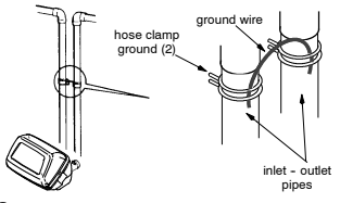
5.INSTALL GROUNDING WIRE (IF NEEDED):
To maintain electrical ground continuity in the house cold water piping, install a #4 copper wire across the removed pipe section, securely clamping it at both ends (see Figure 2) — parts not included.
NOTE: A 3–valve bypass system maintains ground continuity.
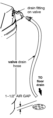
6.CONNECT AND RUN THE VALVE DRAINHOSE:
- Take a length of 3/8” or 7/16” inside diameter hose and attach to the valve drain fitting. So water pressure does not blow the hose off, use a hose clamp to secure in place.
- Locate the other end of the hose at a suitable drain point…floor drain, sump, laundry tub, etc. Check and comply with local codes.
IMPORTANT: Use high quality, thick–wall hose that will not easily kink or collapse. The water softener will not work if water cannot exit this hose during regenerations.
- Tie or wire the hose in place at the drain point. Water pressure will cause it to whip during the backwash and fast rinse cycles of regeneration. Also provide an air gap of at least 1–1/2” between the end of the hose and the drain point. An air gap prevents possible siphoning of sewer water, into the softener, if the sewer should ‘‘back–up’’.
- If raising the drain hose overhead is required to get to the drain point, do not raise higher than 8’ above the floor. Elevating the hose may cause a back–pressure that could reduce brine draw during regenerations.
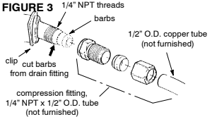
CONNECTING A RIGID VALVE DRAIN TUBE
To adapt a copper drain tube to the softener, use a hacksaw to cut the barbed end from the drain fitting as shown. Buy a compression fitting (1/4” female pipe thread x 1/2”O.D. tube) and needed tubing from your local hardware store.
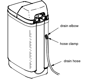
7.CONNECT AND RUN THE BRINE TANK OVERFLOW HOSE (see Figure 4):
- Attach a length of 3/8” or 7/16” I.D. hose to the drain elbow, installed in step 2, page 7. Use a hose clamp to hold it in place.
- Locate the other end of the hose at the drain point. DO NOT ELEVATE THIS HOSE HIGHER THAN THE ELBOW ON THE BRINE TANK. DO NOT TEE THIS HOSE TO THE VALVE DRAIN HOSE.
NOTE: This drain is for safety only. If the brine tank should over–fill with water, the excess is carried to the drain.
8.FLUSH PIPES, EXPEL AIR FROM SOFTENER, AND TEST YOUR INSTALLATION FOR WATER LEAKS:
CAUTION: To avoid water or air pressure damage to softener inner parts, be sure to do the following steps exactly as listed.
A. Fully open two cold, soft water faucets nearby the softener.
B. Place bypass valve(s) in ‘‘bypass’’ position. On a single valve, slide the stem into BYPASS. On a 3–valve system, close the inlet and outlet valves, and open the bypass valve…see page 6.
C. Fully open the house main water pipe shutoff valve. Observe a steady flow from both opened faucets.
D. Place bypass valve(s) in ‘‘service”, EXACTLY as follows. KEEP SOFT WATER FAUCETS OPEN.
- SINGLE BYPASS VALVE: SLOWLY, slide the valve stem toward ‘‘service’’, pausing several times to allow the softener to pressurize slowly.
- 3–VALVE BYPASS: Fully close the bypass valve and open the outlet valve. SLOWLY, open the inlet valve, pausing several times to allow the softener to pressurize slowly.
E. After about three minutes, open a HOT water faucet for one minute, or until all air is expelled, then close.
F. Close both cold water faucets.
G. Check your plumbing work for leaks and fix right away, if any are found. BE SURE TO OBSERVE PREVIOUS CAUTION NOTES.
H. Turn on the gas or electric supply to the water heater. Light the pilot, if applicable.
9.ADD WATER AND SALT TO THE BRINE TANK:
- Remove the salt storage area cover. Add about 3 gallons of water into the tank. DO NOT ADD INTO THE BRINEWELL.
- *Add NUGGET, PELLET or coarse SOLAR water softener salt to the salt storage tank. Do not use rock, block, granulated, and ice cream making salts. Also see page 16. Maximum salt storage capacity is 200 lbs. For best results, North Star recommends Morton R System Saver R Pellets for use in this water softener.
*Note: If the softener is installed in a humid basement or other damp area, it is better to fill the tank more often using less salt (see salt bridging in the maintenance section). Eighty to 100 lbs of salt will last for several months, depending on water hardness, family size, and model of softener.
10.CONNECT TO ELECTRICAL POWER:
- The softener works on 28V DC electrical power. The included power supply converts 120V AC household power to 28V DC. Plug the power supply into a 120V, 60 Hz electrical outlet. Be sure the outlet is always ‘‘live’’ so it can not be switched off by mistake.
11.PROGRAM THE TIMER:
- ELECTRONIC DEMAND TIMER.
PROGRAMMING THE ELECTRONIC DEMAND TIMER
TIMER SETTINGS REQUIRED…upon installation, and after an extended power outage.
NOTES:
D WHEN THE POWER SUPPLY IS PLUGGED INTO THE ELECTRICAL OUTLET (STEP 10, PAGE 9), a flashing 12:00AM and PRESENT TIME show in the display area. Program the timer as instructed below. If
- – – – is flashing, use the UP + button to set the code to Sr14. If you pass by the correct code number, use the DOWN — button. Then, press the SELECT button and program the timer below. If the wrong code shows for your model, see Manual Initiated Electronic Diagnostics
- A ‘‘beeper’’ sounds while pressing buttons for timer programming. One beep signals a change in the timer display. Repeated beeps means the timer will not accept a change from the button you have pressed, and you should use another button.
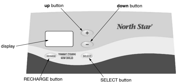
- To set the timer, you will use the UP +, DOWN — and SELECT buttons.
SET PRESENT TIME OF DAY
NOTE: If the words PRESENT TIME do not show in the display, press the SELECT button until they do.
- Press the UP or DOWN button to set. The UP button moves the time ahead; DOWN moves the time backward.
NOTE: Each press of the buttons changes the time by one minute. Holding the buttons in changes the time 32 minutes each second.
If the present time is between noon and midnight, be sure PM shows.
If the present time is between midnight and noon, be sure AM shows.

- When the present time shows, press SELECT to set.
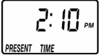
SET WATER HARDNESS NUMBER
NOTE: If a flashing 25 (factory default) and the word HARDNESS do not show in the display, press SELECT until they do.
- Press the UP or DOWN button to set your water hardness number in the display. DOWN moves the display down to 1. UP moves the display up to 50.
NOTE: Each press of a button changes the display by 1 between 1 and 25. Above 25, the display changes 5 at a time; 25, 30, 35, etc. Holding a button in changes the numbers twice each second. See the specified maximum hardness.
- When your water hardness number shows, press SELECT to set.
You can get the grains per gallon (gpg) hardness of your water supply from a water analysis laboratory, or call and ask your local water department, if you are on a municipal supply. If water contains iron, add to the water hardness at a ratio of 5 grains for each 1 ppm of iron.
SET REGENERATION (STARTING) TIME
NOTE: RECHARGE TIME and a flashing 2:00 AM (factory default) should show in the display. This is a good time for regeneration to start (over in about 2 hours) in most households because water is not in use. HARD WATER is bypassed to house faucets during regeneration.
If no change is needed, go to step 2. To change this time, if desired, do step 1.
- Press the UP or DOWN button to set the desired regeneration start time.
Be sure to observe the AM or PM, as you did when setting the time of day.

NOTE: Each press of the buttons changes the time by one hour. Holding the buttons in changes the time twice each second.
2.Press the SELECT button once more.
The display shows the present time of day.

SANITIZING PROCEDURES
Care is taken at the factory to keep your water softener clean and sanitary. Materials used to make the softener will not infect or contaminate your water supply, and will not cause bacteria to form or grow. However, during shipping, storage, installing and operating, bacteria could get into the softener. For this reason, sanitizing as follows is suggested when installing.
- Be sure to complete all installation steps, including timer programming.
- Pour about 3/4 oz of common 5.25% household bleach (Clorox, Linco, Bo Peep, White Sail, Eagle, etc.,) into the brinewell.
- Start a recharge: Press the RECHARGE button and hold for 3 seconds, until RECHARGE NOW begins to flash in the display. This recharge draws the sanitizing bleach into and through the water softener to sanitize it. Any air remaining in the unit is purged to the drain.
- After the recharge has completed, fully open a cold water faucet, downstream from the softener, and allow 50 gallons of water to pass through the system. This should take at least 20 minutes. Close the faucet.
NOTE: Sanitizing is recommended by the water Quality Association for disinfecting. On some water supplies, they suggest periodic sanitizing.
NOTE: When the above sanitizing regeneration is over, all remaining bleach is flushed from the conditioner and your house COLD water supply is fully soft immediately. However, your water heater is filled with hard water and, as hot water is used, it will refill with soft water.
When all the hard water is replaced, in the water heater, hot only, and mixed hot and cold water will be fully soft. If you want totally soft water immediately, after the above regeneration, drain the water heater until the water runs cold. If you do drain the water heater, use extreme care as the water could cause severe burns.
WATER AND WATER CONDITIONING
WATER
Man’s very existence depends on water. It is one of the basic commodities of life. Water is best as nature provides it, is a common misconception. Practically all natural water needs refinement or treatment to make it safe to drink or more satisfactory to use.
The earth’s water supply cycle starts in the upper cloud layers. As it falls to the earth as rain or snow, it picks up impurities and gases from the atmosphere. Landing on earth, it seeps over and through the ground, dissolving earth minerals. Passing through limestone, it dissolves calcium and magnesium, the hardness minerals. Iron deposits impart iron to the water. Acidity and sediments are other water conditions.
Municipal water supplies come from surface reservoirs, such as lakes and rivers, or from underground reservoirs. Usually, municipalities chlorinate the water to make it safe to drink. Sediment is removed by filtration. Tastes and odors are reduced or eliminated. The water is conditioned to comply with certain specifications. However, hardness minerals, tastes and odors are not always reduced to the most
desirable levels.
Underground reservoirs provide our private water supplies. Because the water is raw and untreated, it can have varying amounts of hardness, iron, tastes, odors, acidity, or combinations of these. Different localities and water levels affect mineral content.
WATER CONDITIONING
Water conditioning is the treatment of four general conditions. These are: Hardness, Iron, Acidity, Sediments.
HARDNESS is a term to describe the presence of calcium and magnesium minerals in water. A chemical analysis accurately measures the amount of minerals in grain weight. For example, one gallon of water with five grains per gallon (gpg) hardness has dissolved minerals, that if solidified, about equals the size of one ordinary aspirin tablet. One gallon of water, 25 gpg hard, has a mineral content equal in size to five aspirin tablets. Water hardness varies greatly across the country. It generally contains from 3 to 100 gpg.
Hard water affects living in general. Hardness minerals combine with soap to make a soap curd. The curd greatly reduces the cleaning action of soap. Precipitated hardness minerals form a crust on cooking utensils, appliances, and plumbing fixtures. Even the tastes of foods are affected. A water softener removes the hardness minerals to eliminate these problems, and others.
Sodium Information: Water softeners using sodium chloride (salt) for regeneration add sodium to the water. Persons on sodium restricted diets should consider the added sodium as part of their overall intake.
IRON in water is measured in parts per million (ppm). The total* ppm of iron, and type or types*, is determined by chemical analysis. Four different types of iron in water are: 1 Ferrous (clear water), 2 Ferric (red water), 3 Bacterial and organically bound iron, 4 Colloidal and inorganically bound iron (ferrous or ferric).
*Water may contain one or more of the four types of iron and any combination of these. Total iron is the sum of the contents.
1. Ferrous (clear water) iron is soluble and dissolves in water. It is usually detected by taking a sample of water in a clear bottle or glass. Immediately after taking, the sample is clear. As the water sample stands, it gradually clouds and turns slightly yellow or brown as air oxidizes the iron. This usually occurs in 15 to 30 minutes. A water softener will remove moderate amounts of this type of iron (see specifications).
2.Ferric (red water), and ¢Bacterial and organically bound irons are insoluble. This iron is visible immediately when drawn from a faucet because it has oxidized before reaching the home. It appears as small cloudy yellow, orange, or reddish suspended particles. After the water stands for a period of time, the particles settle to the bottom of the container. Generally these irons are removed from water by filtration. Chlorination is also recommended for bacterial iron.
4.Colloidal and inorganically bound iron is of ferric or ferrous form that will not filter or exchange out of water. In some instances, treatment may improve colloidal iron water, but always CONSULT A QUALIFIED WATER CHEMISTRY LAB before attempting to treat it. Colloidal iron water usually has a yellow appearance when drawn. After standing for several hours, the color persists and the iron does not settle,
but remains suspended in the water.
Iron in water causes stains on clothing and plumbing fixtures. It negatively affects the taste of food, drinking water, and other beverages.
ACIDITY or acid water is caused by carbon dioxide, hydrogen sulfide, and sometimes industrial wastes. It is corrosive to plumbing, plumbing fixtures, water heaters, and other water using appliances. It can also damage and cause premature failure of seals, diaphragms, etc., in water handling equipment.
A chemical analysis is needed to measure the degree of acidity in water. This is called the pH of water. Water testing below 6.9 pH is acidic. The lower the pH reading, the greater the acidity. A neutralizer filter or a chemical feed pump are usually recommended to treat acid water.
SEDIMENT is fine, foreign material particles suspended in water. This material is most often clay or silt. Extreme amounts of sediment may give the water a cloudy appearance. A sediment filter normally corrects this condition.
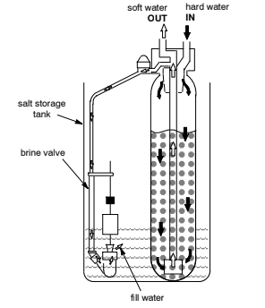
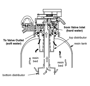
HOW THE WATER SOFTENER WORKS
SOFT WATER SERVICE, AND REGENERATION
SERVICE
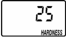
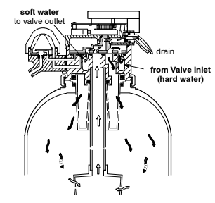
When the softener is providing soft water, it is called “Service”. During service, hard water flows from the house main water pipe into the softener. Inside the softener resin tank is a bed made up of thousands of tiny, plastic resin beads. As hard water passes through the bed, each bead attracts and holds the hardness minerals. This is called ion-exchanging. It is much like a magnet attracting and holding metals.
Water without the hardness minerals (soft water) flows from the softener and to the house pipes.
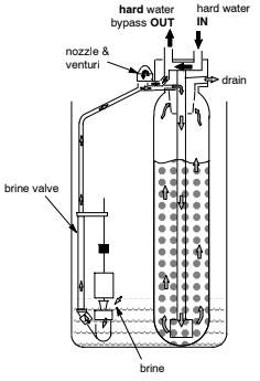
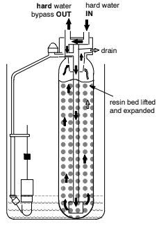
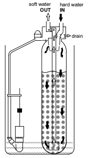
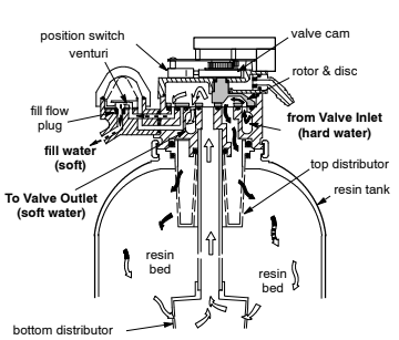
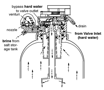
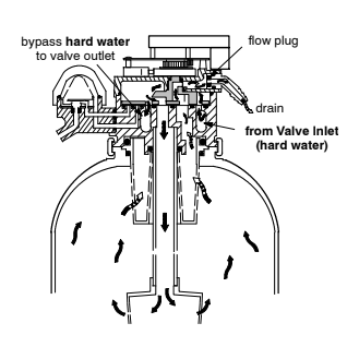
After a period of time, the resin beads hold all of the hardness minerals they can and cleaning is needed to remove them. This cleaning is called regeneration, or recharge. The demand timer automatically determines when regenerations occur. Regeneration is started at 2:00 a.m. (factory setting) by the softener timer, and consists of five stages or cycles. These are: FILL, BRINING, BRINE RINSE, BACKWASH, and FAST RINSE.
REGENERATION
- FILL: Salt, dissolved in water, is called brine. Brine is needed to clean the hardness minerals from the resin beads. To make the brine, water flows into the salt storage area during the fill stage as shown on page 15.
- BRINING: During brining, brine travels from the salt storage area, into the resin tank. Brine is the cleaning agent needed to remove the hardness minerals from the resin beads. The hardness minerals, and brine are discharged to the drain. The nozzle and venturi create a suction to move the brine, maintaining a very slow rate to get the best resin cleaning with the least salt.
- BRINE RINSE: After a pre–measured amount of brine is used, the brine valve closes. Water continues to flow in the same path as during brining, except for the discontinued brine flow. Hardness minerals and brine flush from the resin tank, to the drain.
- BACKWASH: During backwash, water travels up through the resin tank at a fast flow rate, flushing accumulated iron, dirt, and sediments from the resin bed and to the drain.
- FAST RINSE: Backwash is followed by a fast flow of water down through the resin tank. The fast flow flushes brine from the bottom of the tank, and packs the resin bed.
After fast rinse, the softener returns to soft water service.
AUTOMATIC HARD WATER BYPASS DURING REGENERATION
For emergency needs, hard water is available to the home during the regeneration cycles. However, you should avoid using HOT water because the water heater will refill with the hard water.
WATER FLOW THROUGH SOFTENER
GENERAL WATER SOFTENER MAINTENANCE
CHECKING THE SALT STORAGE LEVEL, AND ADDING SALT
Brine (salt dissolved in water) is needed for each and every regeneration. The water for making brine is metered into the salt storage area by the softener valve and electronic controller. However, you must maintain a level of salt in the tank.
NOTE: In humid areas, it is best to add less salt, more often. WHEN TO ADD SALT: Check the salt level a few weeks after you install the softener and every week after that. Add when the brine tank is from 1/3 to 1/2 full. Never allow the softener to use all the salt before
you add more. Without salt, you will soon have hard water.
Use clean water softener salts only, at least 99.5% pure. NUGGET, PELLET or coarse SOLAR salts are recommended. Do not use rock, block, granulated, and ice cream making salts. They contain dirt and sediments, or mush and cake, and will create maintenance problems. For best results, North Star recommends MortonR System SaverR Pellets for use in this water softener.
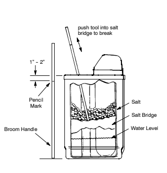
BREAKING A SALT BRIDGE
Sometimes, a hard crust or salt bridge forms in the salt storage area. It is usually caused by high humidity or the wrong kind of salt. When the salt bridges, an empty space forms between the water and salt. Then salt will not dissolve in the water to make brine.
If the brine tank is full of salt, it is hard to tell if you have a salt bridge. Salt is loose on top, but the bridge is under it. The following is the best way to check for a salt bridge.
Salt should be loose all the way to the bottom of the tank. Take a broom handle, or like tool, and carefully push it down into the salt, working it up and down. If the tool strikes a hard object (be sure it’s not the bottom or sides of the tank), it’s most likely a salt bridge. Carefully break the bridge with the tool. DO NOT pound on the walls of the tank.
If the wrong kind of salt made the bridge, take it out. Then fill the tank with nugget or pellet salt only. For best results, North Star recommends MortonR System SaverR Pellets for use in this water softener.
CLEANING IRON OUT OF THE WATER SOFTENER
Your water softener takes hardness minerals (calcium and magnesium) out of the water. Also, it can control some “clear water” iron. With clear water iron, water from a faucet is clear when first put into a glass. After 15 to 30 minutes, the water begins to cloud or turn rust colored. A water softener WILL NOT remove any iron that makes the water cloudy or rusty as it comes from the faucet (called red water iron). To take red water iron out of water, or over the maximum of clear water iron, an iron filter or other equipment is needed. Your local dealer has trained people to help you with iron water problems.
If your water supply has clear water iron, periodic resin bed cleaning is needed. Clean the bed at least every six months, or more often if iron appears in the soft water between treatments. Follow directions on the resin bed cleaner container.
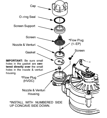
CLEANING THE NOZZLE AND VENTURI ASSEMBLY
A clean nozzle and venturi is needed for the softener to work right. This small unit makes the suction to move brine from the salt storage area to the resin tank during regeneration. If it becomes plugged with sand, silt, dirt, etc., the softener will not work and you will get hard water.
To get to the nozzle and venturi, remove the softener top cover. Be sure the softener is in service cycle (no water pressure at nozzle and venturi). Then, while holding the nozzle & venturi housing with one hand, turn off the cap. Lift out the screen support and screen, then the nozzle and venturi. Wash and rinse the parts in warm water until clean. If needed, use a small brush to remove iron or dirt. Also check and
clean the gasket.
NOTE: Some models have a small flow plug located in the nozzle and venturi, and/or a small cone shaped screen in the housing. Be sure to check and clean these parts, if your model is so equipped.
Carefully replace all parts in the correct order. Lubricate the o-ring seal with silicone grease and place in position. Install and tighten the cap, BY HAND ONLY. DO NOT OVER TIGHTEN, WHICH MAY BREAK THE CAP OR HOUSING.
SERVICE CHECKLIST
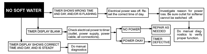
NO SOFT WATER
No salt in storage tank: then start a regeneration, or recharge.
Power supply unplugged at wall outlet, or disconnected from timer: Reconnect to electrical power and start a regeneration, or recharge.
Fuse blown, circuit breaker popped, or circuit mistakenly switched off: Check and resolve as needed. Then, start a regeneration, or recharge.
Plumbing bypass valve(s) in ‘‘bypass’’ position: and position valve(s) as needed to direct soft water to house pipes. Then, start a regeneration, or recharge.
Timer not programmed: See…. Electronic Demand Timer –
Nozzle & venturi dirty, or salt in storage tank bridged:and above to clean. Then, start a regeneration, or recharge.
WATER INTERMITTENTLY HARD
Possible increase in water hardness: See…. Electronic Demand Timer
Hot water used when softener is regenerating: The water heater will refill with hard water… see Automatic Hard Water Bypass During Regenerations.
Leaking faucet or toilet valve: A small leak will waste hundreds of gallons of water in just a few days. Fix all water leaks immediately.
ELECTRONIC DEMAND TIMER FEATURES, AND SERVICE
NOTE:THE TIMER TO THE CORRECT TIME OF DAY, WATER HARDNESS NUMBER, AND RECHARGE START TIME.
NORMAL OPERATION, TIMER DISPLAYS
During normal operation, the present time of day, and AM or PM, show in the time display area.

feature: OPTIONAL RECHARGE CONTROLS
Sometimes, a manually started regeneration (recharge) may be desired, or needed. Two examples are:
… You have used more water than usual (house guests, extra washing, etc.) and you may run out of soft water before the next regeneration.
… You did not refill the storage tank with salt before it was all gone.
Use one of the following features to start a regeneration immediately, or at the next preset regeneration start time.
RECHARGE NOW
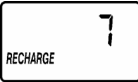
Press and hold in the RECHARGE button until RECHARGE NOW starts to flash in the time display area. The softener begins an immediate regeneration, and when over in about two hours, you will have a new supply of soft water. Once started, you cannot cancel this regeneration.

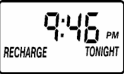
RECHARGE TONIGHT
Press and release the RECHARGE button, and RECHARGE TONIGHT flashes in the time display area. A regeneration will occur at the next preset regeneration start time. If you decide to cancel this regeneration, touch the same button once more.
VACATION NOTE
North Star Demand water softeners regenerate only while water is used and softening capacity must be restored. For this reason, the softener will not regenerate when you are away from home for extended periods.
feature: PROGRAM MEMORY
If electrical power to the softener is interrupted, the time display is blank, but the timer keeps correct time for about 6 hours. When power is restored, you ave to reset the present time only if the display is flashing. All other settings are maintained and never require resetting unless a change is desired.
If the time is flashing after a long power outage, the softener continues to work as it should to provide you with soft water. However, regenerations may occur at the wrong time of day until you reset the timer to the correct time of day.
feature: SALT EFFICIENCY
When this feature is ON, the unit will operate at salt efficiencies of 4000 grains of hardness per pound of salt or higher. (May recharge more often using smaller salt dosage and less water). Press and hold the SELECT button for 3 seconds until the following screen is diplayed.
Press and release the SELECT button once and the SALT EFFICIENCY display shows. Use the UP / Down buttons to change the ON / OFF displays. Press SELECT once more to return to normal operating screens. When this is ON the efficiency icon will show in the upper right hand corner of the display.

California Efficiency Requirement
Your water softener has a “High Efficiency” feature with an “ON” or “OFF” setting. This softener setting is shipped in the “OFF” position, which utilizes the maximum rated capacity while most often achieving maximum salt efficiencies. When installing this unit in the State of California, you MUST turn this setting to the “ON” position which may initiate more frequent recharges, however it will operate at 4000 grains per pound of salt or higher. If you wish to turn the Salt Efficiency feature “ON” ( icon will show in display), follow the instructions.
feature / service: AUTOMATIC ELECTRONIC DIAGNOSTICS
The timer computer has a self–diagnostic function for the electrical system (except input power and water meter). The computer monitors the electronic components and circuits for correct operation. If a malfunction occurs, an error code appears in the timer display.
The following chart (below) shows the error codes that could appear, and possible defects for each code. While an error code is displayed, all timer buttons are inoperable except for the SELECT button.
SELECT remains operational so the service person can make the Manual Initiated Electronic Diagnostics to further isolate the defect, and check the water meter.
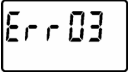
| ERROR CODE DISPLAYED | ||
| Err 01 Err 03 Err 04 | Err 05 | |
| POSSIBLE DEFECT | wiring harness, or connection to switch ‘ position switch ‘ motor inoperative ‘ valve defect causing high torque | timer (PWA) |
| TO REMOVE AN ERROR CODE: (1) unplug power supply (2) correct defect (3) plug power supply back in (4) Wait for at least 12 minutes. The error code will return if the reason for the error code was not corrected. |
service: TIMER / SOFTENER, SERVICE CHECKOUT PROCEDURE
If you are not getting soft water, and an error code is not displayed, use the procedures below to find the problem. First, make the following visual checks.
VISUAL CHECKS: (1) Is there electrical power to the outlet the softener’s power supply is plugged into? (2) Is there salt in the storage tank? (3) Is the plumbing bypass valve(s) directing water for soft water service? Is the valve drain hose open to the drain, not elevated too high, and unobstructed? If you do not find a problem with the visual checks, continue below.
service: MANUAL INITIATED ELECTRONICS DIAGNOSTIC
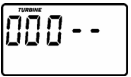
- To enter diagnostics, press and hold the SELECT button until (000 — –) shows in the display.
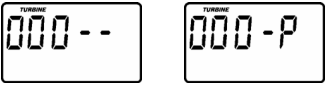
(A)The first 3 digits indicate water meter operation as follows:
000 (steady) = soft water not in useno flow through the meter.
OPEN A NEARBY SOFT WATER FAUCET
000 to 199 (continual) = repeats display for each gallon of water passing through the meter.
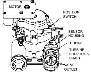
If you don’t get a reading in the display, with faucet open, pull the sensor from the valve outlet port. Pass a small magnet back and forth in front of the sensor. You should get a reading in the display. If you get a reading, unhook the in and out plumbing and check the turbine for binding.
(B) The letter (P) and dash(es) indicate POSITION switch operation. The letter appearing means the switch is closed; the dash means the switch is open.
Use the RECHARGE button to manually advance the valve into each cycle and check correct switch operation.
| CORRECT SWITCH DISPLAYS | VALVE CYCLE STATUS |
| — — | Valve in service, fill, brining, backwash or fast rinse position. |
| — P | Valve rotating from one position to another. |
C. While in this diagnostic screen, the following information is available and may be beneficial for various reasons. This information is retained by the computer from the first time electrical power is applied to the face plate.
. … Press the UP button to display the number of days this face plate has had electrical power applied.

Press the DOWN button to display the number of regenerations initiated by this face plate since the model code number was entered.
- Press the SELECT button and hold in 3 seconds until a model code appears in the display.
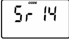
For correct softener operation, the model code must be Sr14.
To reset the code, press the UP or DOWN button until the correct number shows.
- Press SELECT to return the present time display. If the code was changed, make ALL the timer settings,
NOTE: If the face plate is left in a diagnostic display (or a flashing display when setting times or hardness), present time automatically
returns if a button is not pressed within 4 minutes.
service: RESETTING TO FACTORY DEFAULTS
To reset the electronic controller to its factory default for all settings (time, hardness, etc.):
- Press the SELECT button and hold it until the display changes twice to show “CODE” and the flashing model code.
- Press the UP button (a few times, if necessary) to display a flashing “SoS”.

- Press the SELECT button, and the electronic controller will restart.
- Set the present time, hardness, etc.
service: MANUAL ADVANCE REGENERATION CHECK
This check verifies proper operation of the valve motor, brine tank fill, brine draw, regeneration flow rates, and other controller functions. First, make the initial checks, and the manual initiated diagnostics.
NOTE: The face plate display must show a steady time (not flashing).
- Press the RECHARGE button and hold in for 3 seconds. RECHARGE NOW begins to flash as the softener enters the fill cycle of regeneration. Remove the brinewell cover and, using a flashlight, observe fill water entering the brine tank.
If water does not enter the tank, look for an obstructed nozzle, venturi, fill flow plug, brine tubing, or brine valve riser pipe.
- After observing fill, press the RECHARGE button to move the softener into brining. A slow flow of water to the drain will begin. Verify brine draw from the brine tank by shining a flashlight into the brinewell and observing a noticeable drop in the liquid level.
NOTE: Be sure a salt bridge is not preventing water with salt contact.
If the softener does not draw brine
- nozzle and/or venturi dirty or defective.
- nozzle and venturi not seated properly on gasket.
- restricted drain (check drain fitting and hose).
- defective nozzle and venturi seal.
- other inner valve defect (rotor seal, rotor & disc, wave washer, etc.).
NOTE: If water system pressure is low, an elevated drain hose may cause back pressure, stopping brine draw.
- Again, press the RECHARGE button to move the softener into backwash. Look for a fast flow of water from the drain hose.
A slow flow indicates a plugged top distributor, backwash flow plug, or drain hose.
- Press RECHARGE to move the softener into fast rinse. Again look for a fast drain flow. Allow the softener to rinse for a few minutes to flush out any brine that may remain in the resin tank from the brining cycle test.
- To return the softener to service, press RECHARGE.
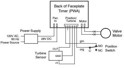
WIRING SCHEMATIC
WATER FLOW THROUGH VALVE
REPAIR PARTS
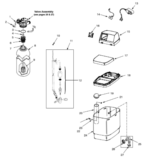
| KEY NO. | PART NO. | DESCRIPTION |
| – | 7331177 | Tank Neck Clamp Kit (includes 2 ea. of Key Nos. 1 & 2) |
| 1 | ↑ | Clamp Section (2 req.) |
| 2 | ↑ | Retainer Clip (2 req.) |
| – | 7112963 | Distributor O–ring Kit (includes Key Nos. 3–5) |
| 3 | ↑ | O–ring, 2–7/8” x 3–1/4” |
| 4 | ↑ | O–ring, 13/16” x 1–1/16” |
| 5 | ↑ | O–ring, 2–3/4” x 3” |
| 6 | 7077870 | Top Distributor |
| 7 | 7105047 | Top Distributor |
| 8 | 7264037 | Repl. Bottom Distributor |
| 9 | 0502272 | Resin Tank, 8” dia x 25” |
| 10 | 7171349 | Resin, 53 lbs (1 cu ft) |
| 11 | 7310163 | Screen, Cone |
| 12 | 7293395 | Brine Valve Assembly |
| 13 | 7337482 | Float, Stem & Guide Assembly |
| 14 | 7309358 | Power Supply, 28V DC |
| 15 | 7266746 | Faceplate Cover (order decal below) |
| 16 | 7269794 | Decal, Faceplate |
| 7266754 | Control Panel | |
| 17 | 7201398 | Salt Hole Cover |
| 18 | 7266762 | Rim |
| 19 | 7155115 | Cover, Brinewell |
| 20 | 7263099 | Brinewell |
| – | 7331648 | Brinewell Mounting Hardware Kit (includes Key Nos. 21–23) |
| 21 | ↑ | Wing Nut, 1/4–20 |
| 22 | ↑ | Screw, 1/4–20 x 5/8” |
| 23 | ↑ | O–ring, 1/4” x 3/8” |
| 24 | 7270737 | Repl. Brine Tank |
| – | 7331258 | Overflow Hose Adaptor Kit (includes Key Nos. 25–27) |
| 25 | ↑ | Adaptor Elbow |
| 26 | ↑ | Grommet |
| 27 | ↑ | Hose Clamp |
| 7139999 | Drain Tubing |
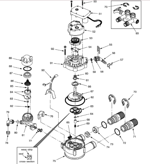
VALVE REPAIR PARTS
READ ALSO: MARLO INCORPORATED WATER SOFTENER INSTALLATION, OPERATION, AND MAINTENANCE MANUAL (MCV Series)
VALVE REPAIR PARTS
| KEY NO. | PART NO. | DESCRIPTION |
| 50 | 7338111 | Screw, #6–19 x 1–3/8” |
| 51 | 7281291 | Motor |
| 52 | 7337474 | Motor Mount |
| 53 | 7284964 | Cam & Gear |
| 54 | 7030713 | Switch |
| – | 7331185 | Drain Hose Adaptor Kit (includes Key Nos. 55–59) |
| 55 | ↑ | Clip, Drain |
| 56 | ↑ | Drain Hose Adaptor |
| 57 | ↑ | Hose Clamp |
| 58 | ↑ | O–ring, 5/8” x 13/16” |
| 59 | ↑ | Flow Plug, 2.0 gpm |
| – | 7129716 | Seal Kit (includes Key Nos. 60–65) |
| 60 | ↑ | O–ring, 7/16” x 5/8” |
| 61 | ↑ | O–ring, 3/4” x 15/16” |
| 62 | ↑ | O–ring, 3–3/8” x 3–5/8” |
| 63 | ↑ | Rotor Seal |
| 64 | ↑ | O–ring, 3/8” x 9/16” |
| 65 | ↑ | Seal, Nozzle & Venturi |
| 66 | 7082087 | Wave Washer |
| 67 | 7199232 | Rotor & Disc |
| 68 | 7092642 | Plug, Drain Seal |
| 69 | 7129889 | Spring |
| 70 | 7116713 | Clip, 3/4”, single (4 req.) |
| 7336397 | Clip, 3/4”, pack of 20 | |
| 71 | 7278442 | Installation Adaptor, 3/4”, single (2 req.) |
| 7336606 | Installation Adaptor, 3/4”, pack of 10 | |
| 72 | 7170288 | O–ring, 15/16” x 1–3/16”, single (2 req.) |
| 7336402 | O–ring, 15/16” x 1–3/16”, pack of 20 |
| – | 7113040 | Turbine & Support Assembly (includes 1 ea. of Key Nos. 73, 74 & 2 ea. of Key No. 72) |
| 73 | ↑ | Turbine Support & Shaft |
| 74 | ↑ | Turbine |
| 75 | 7082053 | Valve Body |
| 76 | 7081201 | Retainer, Nozzle & Venturi |
| 77 | 7170319 | O–ring, 1/4” x 3/8” (2 req.) |
| 78 | 1202600 | Nut–Ferrule |
| 79 | 7120526 | Elbow |
| 80 | 7292323 | O–ring, 3/16” in. x 7/16” |
| – | 7187065 | Nozzle & Venturi Assembly (includes Key Nos. 81–89) |
| 81 | 7081104 | Housing, Nozzle & Venturi |
| 82 | 7095030 | Cone Screen |
| 83 | 1148800 | Fill Flow Plug, .3 gpm |
| 84 | 7187772 | Nozzle & Venturi Kit w/Gasket |
| 7204362 | Gasket only, single | |
| 7336486 | Gasket only, pack of 20 | |
| 85 | 0521829 | Flow Plug, .1 gpm |
| 86 | 7146043 | Screen |
| 87 | 7167659 | Screen Support |
| 88 | 7170262 | O–ring, 1–1/8” x 1–3/8”, single |
| 7336436 | O–ring, 1–1/8” x 1–3/8”, pack of 20 | |
| 89 | 7199729 | Cap |
| 90 | 7309803 | Sensor Housing/Wiring Harness Asm. |
| 91 | 7337466 | Valve Cover |
| 92 | 7074123 | Screw, #10–14 x 2” (5 req.) |
| 93 | 7278434 | Bypass Valve Assembly, 3/4”, (incl. 2 ea. of Key No. 72) |
PARTS RETURN TAGS
If you have a defective part or assembly under warranty, please fill in a parts return tag. Cut out the tag and include it with the defective part when you return it to the place where you purchased the conditioner. To avoid destroying the repair parts information on the reverse side , make a photo copy of the return tags to use.
PARTS RETURN TAG
CUSTOMER’S NAME_____________
STREET ADDRESS _____________
CITY________ STATE ________ ZIP CODE ________
CONDITIONER MODEL NUMBER _____________ SERIAL NUMBER _____________
DATE PURCHASED _____________ DATE PART FAILED _____________
North Star
1890 Woodlane Drive
Woodbury, MN 55125
You can download the PDF version of the NORTH STAR WATER CONDITIONER MODEL NSC15ED USER’S MANUAL here.