Important Safety Instructions
Please save these instructions.
This manual contains important safety, installation, and operating instructions for the charge controller. The following symbols are used throughout the manual to indicate potentially dangerous conditions or important safety information.
WARNING: Indicates a potentially dangerous condition. Use extreme caution when performing this task.
CAUTION: Indicates a critical procedure for safe and proper operation of the controller
NOTE: Indicates a procedure or function that is important to the safe and proper operation of the controller.
General Safety Information
- Read all of the instructions and cautions in the manual before beginning the installation.
- There are no serviceable parts for this controller. Do NOT disassemble or attempt to repair the controller.
- Do NOT allow water to enter the controller.
- Make sure all connections going into and from the controller are tight.
Charge Controller Safety
- NEVER connect the solar panel array to the controller without a battery. The battery must be connected first.
- Ensure input voltage does not exceed 100 VDC to prevent permanent damage.
- Use the Open Circuit (Voc) to make sure the voltage does not exceed this value when connecting panels together.
- Do not exceed 20A (Tracer-2210RN) or 40A (Tracer-4210RN). The Short Circuit (Isc) of the solar array should be less than 20A (Tracer-2210RN) or 40A (Tracer- 4210RN).
Battery Safety
- Use only sealed lead-acid, flooded, or gel batteries which must be deep cycle.
- Explosive battery gases may be present while charging. Be certain there is enough ventilation to release the gases.
- Be careful when working with large lead acid batteries. Wear eye protection and have fresh water available in case there is contact with the battery acid.
- Carefully read battery manuals before operation.
- Do NOT let the positive (+) and negative (-) terminals of the battery touch each other.
- Recycle battery when it is replaced.
- Over-charging and excessive gas precipitation may damage the battery plates and activate material shedding on them. Too high of an equalizing charge or too long of one may cause damage. Please carefully review the specific requirements of the battery used in the system.
- Equalization is carried out only for non-sealed / vented/ flooded / wet cell lead acid batteries.
- Do NOT equalize sealed / VRLA type AGM / Gel cell batteries UNLESS permitted by battery manufacturer.
WARNING: Connect battery terminals to the charge controller BEFORE connecting the solar panel(s) to the charge controller. NEVER connect solar panels to charge controller until the battery is connected.
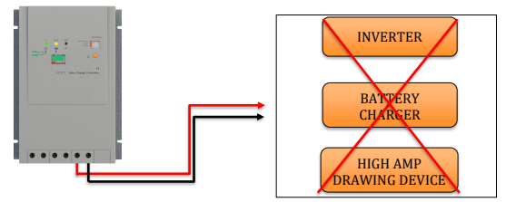
WARNING: Do NOT connect any inverters or battery charger into the load terminal of the charge controller.
WARNING: Once equalization is active in the battery charging, it will remain in this stage as long as there is adequate charging current from the solar panel. There should be NO load on the batteries when in equalization charging stage.
General Information
The RENOGY MPPT series controller is suitable for off-grid solar applications. It protects the battery from being over-charged by the solar modules and over-discharged by the loads. The controller features a smart tracking algorithm that maximizes the energy from the solar PV module(s) and charge the battery. At the same time, the low voltage disconnect function (LVD) will prevent the battery from over discharging.
The MPPT Charge Controller charging process has been optimized for long battery life and improved system performance. The comprehensive self-diagnostics and electronic protection functions can prevent damage from installation mistakes or system faults. In addition, the charge controller has an RJ45 interface to allow communication with a Tracer meter for remote monitoring.
Key Features
- 12V / 24V auto recognition.
- Advanced maximum power point tracking technology to optimize the use of the PV system.
- Peak conversion efficiency of 97 %, high Tracking efficiency of 99%.
- Fast sweeping of the entire I-V curve, several seconds tracking speed.
- Widely used, automatic recognition of day and night.
- Timer function with 1-15 hour option for streetlight.
- Unique dual timer function; enhance the flexibility lighting systems.
- Deep Cycle Sealed, Gel and Flooded battery option.
- Adopting temperature compensation and correcting the charging and discharging parameters automatically, improving battery lifetime.
- Electronic protection: Overcharging, over-discharging, overload, and short circuit.
- Reverse protection: Any combination of solar module and battery, without causing damage to any component.
- Excellent thermal design and natural air-cooling.
- RJ45 interface for use with the remote meter MT-5, convenient to check operating parameters of controllers.
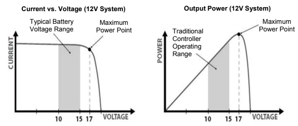
MPPT Technology
The MPPT Charge Controller utilizes Maximum Power Point Tracking technology to extract maximum power from the solar module(s). The tracking algorithm is fully automatic and does not require user adjustment. MPPT technology will track the array’s maximum power point voltage (Vmp) as it varies with weather conditions, ensuring that the maximum power is harvested from the array throughout the course of the day.
Current Boost
In many cases, the MPPT charge controller will “boost” up the current in the solar system.
The current does not come out of thin air. Instead, the power generated in the solar panels is the same power that is transmitted into the battery bank. Power is the product of Voltage (V) x Amperage (A). Therefore, assuming 100% efficiency:
Power In = Power Out
Volts In * Amps In = Volts out * Amps out
Although MPPT controllers are not 100% efficient, they are very close at about 92-95% efficient. Therefore, when the user has a solar system whose Vmp is greater than the battery bank voltage, then that potential difference is proportional to the current boost. The voltage generated at the solar module needs to be stepped down to a rate that could charge the battery in a stable fashion by which the amperage is boosted accordingly to the drop. It is entirely possible to have a solar module generate 8 amps going into the charge controller and likewise have the charge controller send 10 amps to the battery bank. This is the essence of the MPPT charge controllers and their advantage over traditional charge controllers. In traditional charge controllers, that stepped down voltage amount is wasted because the controller algorithm can only dissipate it as heat. The following demonstrates a graphical point regarding the output of MPPT technology.
Limiting Effectiveness
Temperature is a huge enemy of solar modules. As the environmental temperature increases, the operating voltage (Vmp) is reduced and limits the power generation of the solar module. Despite the effectiveness of MPPT technology, the charging algorithm will possibly not have much to work with and therefore there is an inevitable decrease in performance. In this scenario, it would be preferred to have modules with higher nominal voltage, so that despite the drop in performance of the panel, the battery is still receiving a current boost because of the proportional drop in module voltage.
Four Charging Stages
The MPPT charge controllers have a 4-stage battery charging algorithm for a rapid, efficient, and safe battery charging. They include: Bulk Charge, Boost Charge, Float Charge, and Equalization.
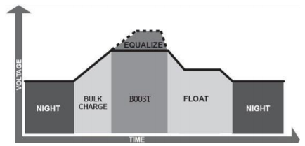
Bulk Charge: This algorithm is used for day to day charging. It uses 100% of available solar power to recharge the battery and is equivalent to constant current.
Boost Charge: When the battery has charged to the Boost voltage set-point, it undergoes an absorption stage which is equivalent to constant voltage regulation to prevent heating and excessive gassing in the battery. The default time for this is 120 minutes in the MPPT controllers but it can be customizable as needed.
Float Charge: After Boost Charge, the controller will reduce the battery voltage to a float voltage set point. Once the battery is fully charged, there will be no more chemical reactions and all the charge current would turn into heat or gas. Because of this, the charge controller will reduce the voltage charge to smaller quantity, while lightly charging the battery. The purpose for this is to offset the power consumption while maintaining a full battery storage capacity. In the event that a load drawn from the battery exceeds the charge current, the controller will no longer be able to maintain the battery to a Float set point and the controller will end the float charge stage and refer back to bulk charging.
Equalization: Is carried out every 28 days of the month. It is intentional overcharging of the battery for a controlled period of time. Certain types of batteries benefit from periodic equalizing charge, which can stir the electrolyte, balance battery voltage and complete chemical reaction. Equalizing charge increases the battery voltage, higher than the standard complement voltage, which gasifies the battery electrolyte.
WARNING: Once equalization is active in the battery charging, it will remain in this stage as long as there is adequate charging current from the solar panel. There should be NO load on the batteries when in equalization charging stage.
WARNING: Over-charging and excessive gas precipitation may damage the battery plates and activate material shedding on them. Too high of equalizing charge or for too long may cause damage. Please carefully review the specific requirements of the battery used in the system.
WARNING: Equalization may increase battery voltage to a level damaging to sensitive DC loads. Ensure that all load allowable input voltages are greater than
the equalizing charging set point voltage.
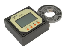
Optional Components
*The MPPT 20A/40ACC is shipped by itself, without any additional components.
Optional components that require a separate purchase:
Renogy MT-5 Tracer Meter for MPPT Charge Controller (MT-5): A self-diagnostics meter ideal for monitoring and displaying the current solar system status information and any error indications the system might be experiencing. It is perfect for circumstances where the user cannot easily access the controller or modify its parameters. It is supplied with a 6.5ft. Cable and a mounting frame that connects to the RJ45 port on the MPPT.
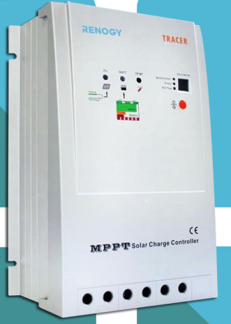
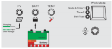
Identification of Parts
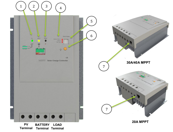
Key Parts
- Charging LED Indicator
- Battery Status LED indicator
- Local Temperature Sensor—acquires ambient temperature to perform temperature compensation for charging and discharging.
- Setting LED Indicators—Work Mode, Timers, and Battery Selection
- LCD Display—load and work more status is displayed
- Set Button—Adjust parameters, cycle through settings, or turn load On/Off
- RJ45 port for MT-5 Tracer (optional accessory)—connects remotely to temperature sensor in order to acquire ambient temperature.
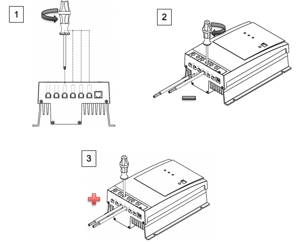
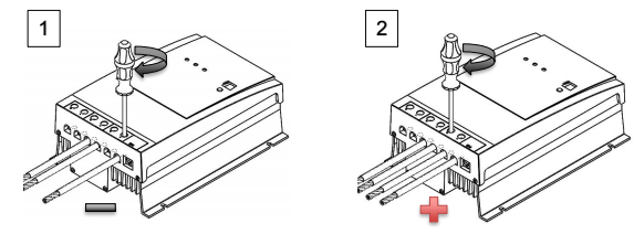
Installation
Recommended tools to have before installation:

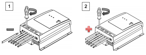
WARNING: Connect battery terminal wires to the charge controller FIRST then connect the solar panel(s) to the charge controller. NEVER connect solar panel to
charge controller before the battery.
WARNING: Do NOT connect any inverters or battery chargers into the load terminal of the charge controller
CAUTION: Do not over-torque or over tighten the screw terminals. This could potentially break the piece that holds the wire to the charge controller.
CAUTION: Refer to the technical specifications for max wire sizes on the controller and for the maximum amperage going through wires.
You are now ready to begin connecting your battery to your charge controller.
Battery
Load (optional)
Solar Panels
MT-5 Tracer (optional)
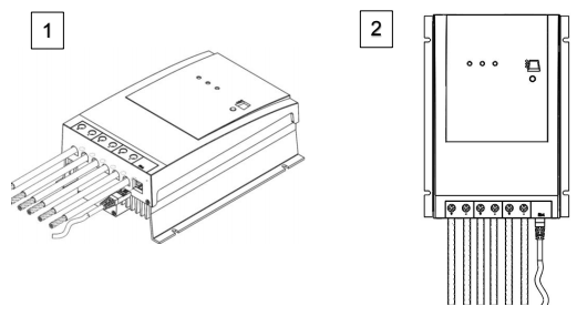
Mounting Recommendations
WARNING: Never install the controller in a sealed enclosure with flooded batteries. Gas can accumulate and there is a risk of explosion.
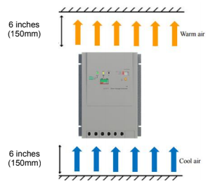
- Choose Mounting Location—place the controller on a vertical surface protected from direct sunlight, high temperatures, and water. Make sure there is good
ventilation. - Check for Clearance—verify that there is sufficient room to run wires, as well as clearance above and below the controller for ventilation. The clearance should be at least 6 inches (150mm).
- Mark Holes
- Drill Holes
- Secure the charge controller.
Operation
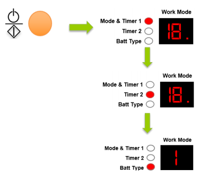
After connecting the battery to the charge controller, the controller will turn on automatically. The MPPT charge controllers are very easy to use and have a simple display for Mode & Timer 1, Timer 2, and Battery Type Information. To cycle through the different digital displays, simply press the big orange Set button. You will notice that a red LED will turn on depending on whichever mode is highlighted followed by a number on the LCD display.
NOTE: The MPPT Charge Controller works automatically and does need the timer(s) function set in order to operate. The timers(s) are simply an added feature
for loads connected directly to the charge controller.
NOTE: In order to adjust a parameter go to your desired LED indicator, hold the orange set button for a little over 5 seconds. Wait until the number inside the Work Mode display flashes. You are now in parameter setting mode and can continually press the orange set button and cycle through the numbers until the desired number is reached. The setting will be in effect once the new number stops flashing.
Load Work Mode Setting
NOTE: In order to adjust a parameter go to your desired LED indicator, hold the orange set button for a little over 5 seconds. Wait until the number inside the Work Mode display flashes. You are now in parameter setting mode and can continually press the orange set button and cycle through the numbers until the desired number is reached. The setting will be in effect once the new number stops flashing.
NOTE: When not using electrical loads, set the timers to “n” (disable) as shown in the Timing Parameters.
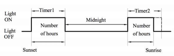
The MPPT Charge Controller is equipped with a programmable dual timer function for the load terminal. Depending on the user setting, the timer(s)’ purpose is to turn on/off the load for a selected amount of time during the day, during the night, or manually to the user’s discretion. Each numerical indicator on the work mode has a specific timer function corresponding to it. There are four Load Control Settings: 1. Dusk to Dawn, 2. Light ON Timer, 3. Test Mode, and 4. Manual Mode.
CAUTION: Be mindful of the maximum load draws for the charge controller.
Overload could result in damage to the charge controller terminal, or the charge controller itself.
NOTE: The load terminal is commonly used for small lights or other low amp drawing devices. The terminal is powered by the battery bank connected to the
charge controller. The load will NEVER draw power directly from the solar panels.
NOTE: With the exception of Manual Mode, none of the dual timer modes will work unless there is a PV array connected to the charge controller.
NOTE: Threshold Voltages can be found under Technical Specifications.
Dusk to Dawn (T1:#0)
The load terminal will be on all night and will be off during the day. The charge controller recognizes that it is nighttime when the solar module voltage goes below the point of NTTV (Night Time Threshold Voltage). The load terminal will recognize this voltage drop and undergo a 10 minute delay before turning on the load terminal.
In that same respect, the charge controller will recognizes day time when the solar module voltage goes above point of DTTV (Day Time Threshold Voltage). The controller will recognize the voltage increase and undergo a 10 minute delay before turning off the load terminal.
NOTE: Only Timer 1 can be set to Dusk to Dawn Mode. As a result, Timer 2 will be disabled when Timer 1 is set to Dusk to Dawn Mode.
Load ON + Timer (T1&T2:#1-15)
The charge controller recognizes that it is nighttime when the solar module voltage goes below the point of NTTV (Night Time Threshold Voltage). The load terminal will recognize this voltage drop and undergo a 10 minute delay before turning on the load terminal. Timer 1 will control the amount of hours the load will remain on after the NTTV and the 10 minute delay. The user will be able to choose between numbers 1 and 15 on Timer 1.
In that same respect, the charge controller will recognizes day time when the solar module voltage goes above point of DTTV (Day Time Threshold Voltage). The controller will recognize the voltage increase and undergo a 10 minute delay before turning off the load terminal. If Timer 1 has already been set to a time frame before night time is over, then Timer 2 will be able control the amount of hours the load turns on again before reaching the DTTV. The user will be able to choose between numbers 1 and 15 on Timer 2.
NOTE: If the charge controller goes above the DTTV then the controller will turn off even if the Timer was set to 15 hours. The timer function works with whichever function it experiences first.
3. Test Mode (T1:#16)
The load terminal will be on all night and will be off during the day. Test mode does not have the 10 minute delay between the NTTV and DTTV giving the user faster results if they are trying to test whether the load terminal timer function is operating correctly.
NOTE: Only Timer 1 can be set to Test Mode. As a result, Timer 2 will be disabled when Timer 1 is set to Test Mode.
Manual Mode (T1:#17)
Manual mode eliminates any timer functions and leaves load control to the discretion of the user. Once manual mode is set, simply use the orange set button to click the load on or off indefinitely.
NOTE: Only Timer 1 can be set to Manual Mode. As a result, Timer 2 will be disabled when Timer 1 is set to Manual Mode.
Timing Parameters
| Timer 1 | Digital Display | Timer 2 |
| Disable | N | Disable |
| Dusk To Dawn | 0 | —– |
| Load on 1 hour AFTER sunset | 1 | Load on 1 hour BEFORE sunrise |
| Load on 2 hour AFTER sunset | 2 | Load on 2 hour BEFORE sunrise |
| Load on 3 hour AFTER sunset | 3 | Load on 3 hour BEFORE sunrise |
| Load on 4 hour AFTER sunset | 4 | Load on 4 hour BEFORE sunrise |
| Load on 5 hour AFTER sunset | 5 | Load on 5 hour BEFORE sunrise |
| Load on 6 hour AFTER sunset | 6 | Load on 6 hour BEFORE sunrise |
| Load on 7 hour AFTER sunset | 7 | Load on 7 hour BEFORE sunrise |
| Load on 8 hour AFTER sunset | 8 | Load on 8 hour BEFORE sunrise |
| Load on 9 hour AFTER sunset | 9 | Load on 9 hour BEFORE sunrise |
| Load on 10 hour AFTER sunset | 10 | Load on 10 hour BEFORE sunrise |
| Load on 11 hour AFTER sunset | 11 | Load on 11 hour BEFORE sunrise |
| Load on 12 hour AFTER sunset | 12 | Load on 12 hour BEFORE sunrise |
| Load on 13 hour AFTER sunset | 13 | Load on 13 hour BEFORE sunrise |
| Load on 14 hour AFTER sunset | 14 | Load on 14 hour BEFORE sunrise |
| Load on 15 hour AFTER sunset | 15 | Load on 15 hour BEFORE sunrise |
| Test Mode | 16 | —— |
| Manual Mode | 17 | —— |
Battery Type Setting
NOTE: In order to adjust a parameter go to your desired LED indicator, hold the orange set button for a little over 5 seconds. Wait until the number inside the Work Mode display flashes. You are now in parameter setting mode and can continually press the orange set button and cycle through the numbers until the desired number is reached. The setting will be in effect once the new number stops flashing.
| Battery Type | Digital Display |
| Sealed Lead Acid | 1 |
| Gel | 2 |
| Flooded | 3 |
LED Indications
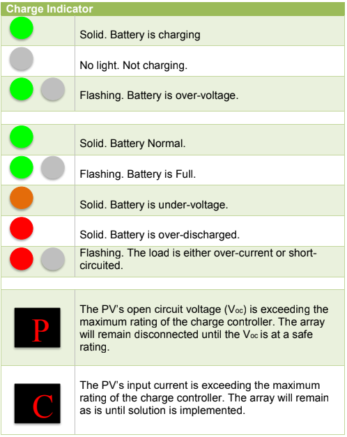
System Status Troubleshooting
| Charge Indicator | Troubleshoot |
| Off during daylight | Ensure that the PV wires are correctly and tightly secured inside the charge controller PV terminals. Use a multi-meter to make sure the poles are correctly connected to the charge controller. |
| Flashing Green | Use a multi-meter to check the battery voltage and make sure it is within specification for the charge controller. NEVER disconnect battery without disconnecting the solar panels first. |
| Battery Indicator | Troubleshoot |
| Solid orange light | Disconnect loads, if any, and let the PV modules charge the battery bank. Use a multi-meter to frequently check on any change in battery voltage to see if condition improves. This should ensure a fast charge. Otherwise, monitor the system and check to see if system improves. |
| Solid Red | The controller will have cutoff the output of the battery to ensure that it charges. Make sure there are no excessive loads and give the system appropriate time and sunlight to charge. Monitor readings with a multi-meter to see if they system improves. |
| Flashing Red Light | System could be overload or short-circuit. Overload: Use a multi-meter to check load draw and limit loads if possible. If no progress, disconnect all loads and gradually reconnect loads to see if the condition improves. Short-circuit: Upon experiencing its first short circuit, the controller will cut off for 10 seconds, and then presume normal operation. Upon the second short-circuit, the controller will not automatically reboot and the user must press the orange button to resume controller working. |
| Work Mode | Troubleshoot |
| The letter “C” | The controller is registering an overcurrent from the solar modules. Check solar panel specifications and verify with a multi-meter to see that they match. Next check to see if the panel specifications (Voc and Isc) are within specification for the charge controller. |
| The letter “P” | The controller is registering an overcurrent from the solar panels. No panels will remain in open circuit unless there is a reduction in the voltage that is safe enough to pass through the controller. Make sure to use a multi-meter to check the specifications of the panel are correct, and that they do not exceed the ratings of the controller. |
Maintenance
WARNING: Risk of Electric Shock! Make sure that all power is turned off before touching the terminals on the charge controller.
For best controller performance, it is recommended that these tasks be performed from time to time.
1. Check that controller is mounted in a clean, dry, and ventilated area. 2. Check wiring going into the charge controller and make sure there is no wire damage or wear.
3. Tighten all terminals and inspect any loose, broken, or burnt up connections. 4. Make sure readings in the LCD and LED are consistent. Take necessary corrective action.
5. Check to make sure none of the terminals have any corrosion, insulation damage, high temperature, or any burnt/discoloration marks.
Fusing
Fusing is a recommended in PV systems to provide a safety measure for connections going from panel to controller and controller to battery. Remember to always use the recommended wire gauge size based on the PV system and the controller.
| NEC Maximum Current for different Copper Wire Sizes | |||||||||
| AWG | 16 | 14 | 12 | 10 | 8 | 6 | 4 | 2 | 0 |
| Max. Current | 10A | 15A | 20A | 30A | 55A | 75A | 95A | 130A | 170A |
| Fuse from Controller to Battery |
| Controller to Battery Fuse = Current Rating of Charge Controller Ex. 30A MPPT CC = 30A fuse from Controller to Battery |
| Fuse from Solar Panel(s) to Controller |
| Ex. 200W; 2 X 100 W panels **Utilize 1.56 Sizing Factor Series: Total Amperage = Isc1 = Isc2 = 5.75A * 1.56 Fuse = minimum of 5.75 * 1.56 = 8.97 = 9A fuse Parallel Total Amperage = Isc1 + Isc2 = 5.75A + 5.75A * 1.56 Fuse = minimum of 11.5 * 1.56 = 17.94 = 18A fuse |
Technical Specifications
Electrical Parameters
| Model | Tracer-2210RN | Tracer-4210RN |
| Nominal system voltage | 12V/24V Auto Recognition | |
| Rated Battery Current | 20A | 40A |
| Rated Load Current | 20A | 20A |
| Max. Battery Voltage | 32V | |
| Max Solar Input Voltage | 100 VDC @ Minimum Working Temperature 92 VDC @ 25°C | |
| Max. Solar Input Power | 12V @ 200W | 12V @ 400W |
| 24V @ 400W 24V @ 800W | ||
| Self-Consumption | ≤10mA(24V) | |
| Temp. Compensation | -5mV/°C/2V | |
| Communication | TTL232 / 8pin RJ45 | |
| Threshold Voltage | NTTV (Night Time Threshold Voltage): 5V @ 12V; x2/24V DTTV (Day Time Threshold Voltage): 6V @ 12V; x2/24V |
Battery Charging Parameters
| Battery | GEL | SEALED | FLOODED |
| High Voltage Disconnect | 16 V | 16 V | 16 V |
| Charging Limit Voltage | 15.5 V | 15.5 V | 15.5 V |
| Over Voltage Reconnect | 15 V | 15 V | 15 V |
| Equalization Voltage | —– | 14.6 V | 15.5 V |
| Boost Voltage | 14.2 V | 14.4 V | 14.6 V |
| Float Voltage | 13.8 V | 13.8 V | 13.8 V |
| Boost Return Voltage | 13.2 V | 13.2 V | 13.2 V |
| Low Voltage Reconnect | 12.6 V | 12.6 V | 12.6 V |
| Under Voltage Recover | 12.2 V | 12.2 V | 12.2 V |
| Under Voltage Warning | 12 V | 12 V | 12 V |
| Low Voltage Disconnect | 11.1 V | 11.1 V | 11.1 V |
| Discharging Limit Voltage | 10.8 V | 10.8 V | 10.8 V |
| Equalization Duration | —– | 2 hours | 2 hours |
| Boost Duration | 2 hours | 2 hours | 2 hours |
Mechanical Parameters
| Model | Tracer-2210RN | Tracer-4210RN |
| Overall Dimension | 169 x 118 x 83mm 6.65 x 4.65 x 3.28in. | 240 x 169 x 91mm 9.45 x 6.65 x 3.58in |
| Mounting Holes | 160 x 80mm 6.29 x 3.15in | 180 x 160mm 7.08 x 6.29in |
| Max Terminal | 10mm2 8 AWG | 25mm2 4 AWG |
| Net Weight | 1.04 kg 2.3 lb. | 2.54 kg 5.6 lb. |
Environment Parameters
| Model | Tracer-2210RN | Tracer-4210RN |
| Working Temperature | -35°C to +55°C | |
| Storage Temperature | -35°C to +80°C | |
| Rated Load Current | 10% to 90% NC | |
| Enclosure | IP30 | |
| Altitude | < 3000m |
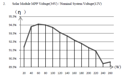
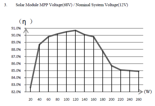
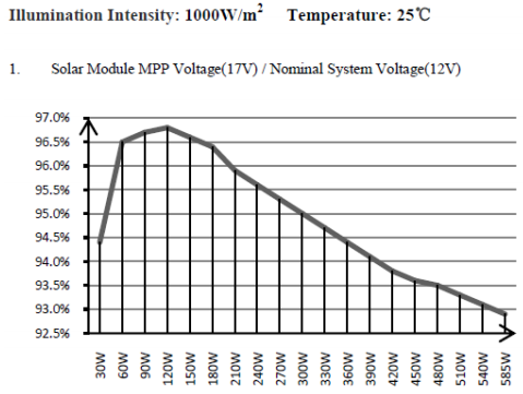
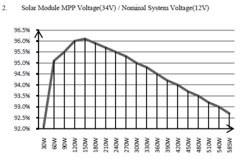
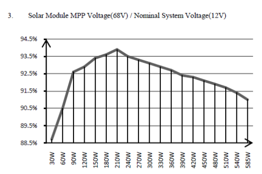
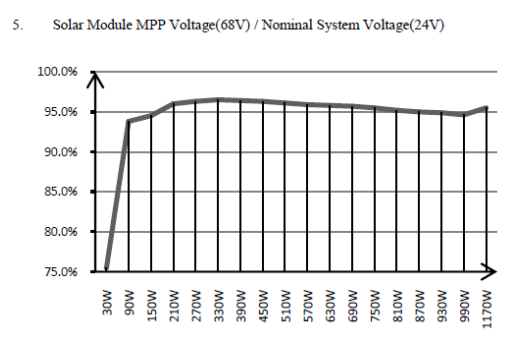
PV Power – Conversion Efficiency Curves—20A MPPT
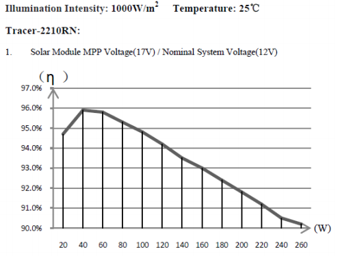
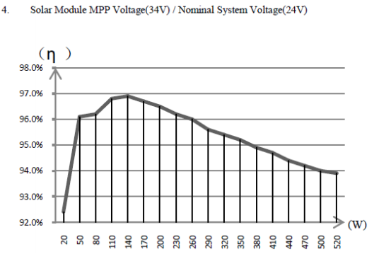
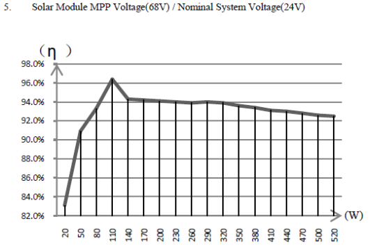
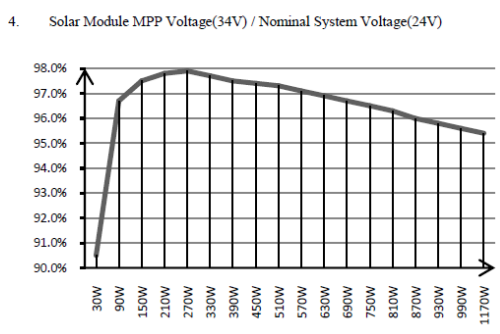
PV Power – Conversion Efficiency Curves—40A MPPT
Dimensions
20A 2210RN
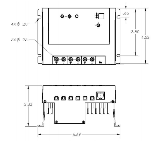
NOTE: All dimensions are in inches
40A 4210RN
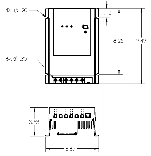
NOTE: All dimensions are in inches
Renogy reserves the right to change the contents of this manual without notice. Revision: 4/5/2016
You can download the PDF version of the RENOGY MPPT Tracer Series User Manual here.