Marlo Incorporated 2227 South Street P.O. Box 044170 Racine, WI 53404-7003 Ph. (262) 681-1300 Fax (262) 681-1318 Info@Marlo-Inc.com
www.Marlo-Inc.com
LIMITED WARRANTY FOR WATER CONDITIONERS AND FILTERS
LIMITED WARRANTY
Marlo Incorporated, P.O. Box 044170, 2227 South Street, Racine, Wisconsin 53404, makes the following guarantees to the original consumer buyer of its water conditioners and filters:
Pressure Vessel – TEN YEARS
Marlo Incorporated guarantees to the original consumer buyer that the water conditioner or filter fiberglass pressure vessel will not rust, corrode, leak or burst during the first ten years of original installation, provided that the conditioner or filter is installed in accordance with manufacturers’ printed instructions and is not subjected to water pressure exceeding 125 psi and/or water temperature exceeding 120o F, providing further that the vessel is not subjected to misuse, alteration, neglect, freezing, fire or accident, and further providing the vessel is not damaged by an act of nature such as, but not limited to, a flood, hurricane or tornado.
If during the first ten years of original installation the pressure vessel proves, after inspection by Marlo Incorporated, to be defective in material or workmanship, Marlo Incorporated will furnish to the original consumer buyer a new replacement vessel without charge. You pay freight one way and local labor charges. No allowance is made for consequential damage, labor, or expense incurred as a result of proven defect.
Brine Tank, Brine Cabinet, or Solution Container – FIVE YEARS
Marlo Incorporated also guarantees to the original consumer buyer, that the water conditioner brine tank or brine cabinet or filter chemical solution container, to be free from defects in material or workmanship for five years after original installation provided that the brine tank, cabinet, or solution container is not subjected to misuse, alteration, neglect, freezing, fire or accident, and further providing the same is not damaged by an act of nature such as, but not limited to, a flood, hurricane, tornado, or ultra-violet ray attack.
If during the five year period the brine tank, cabinet, or solution container proves, after inspection by Marlo Incorporated, to be defective in materials or workmanship, Marlo Incorporated, will replace the same with a new brine tank, cabinet, or solution container without charge. You pay freight one way and local labor charges. No allowance is made for consequential damage, labor, or expense incurred as a result of proven defect.
Valve Module – FIVE YEARS
Marlo Incorporated also guarantees to the original consumer buyer that the water conditioner or filter, noryl plastic module valve or brass valve to be free from defects in material and workmanship for five years after original installation. If during this five year period the valve module proves, after inspection by Marlo Incorporated, to be defective in materials or workmanship, Marlo Incorporated will replace or, at Marlo Incorporated’s sole option, repair the same without charge. You pay freight one way and local labor charges. No allowance is made for consequential damage, labor, or expense incurred as a result of proven defect.
General Provisions
Marlo Incorporated assumes no responsibility with respect to any portion of these warranties in the event of abuse, misuse or negligence by the original consumer buyer or for failure to meet the terms of these warranties caused by strikes, government regulations, material shortages or circumstances beyond Marlo Incorporated’s control.
The warranties set forth herein are contingent upon receipt by Marlo Incorporated of written notice of any defect within thirty days after the same is discovered and upon the proper installation and operation of the water conditioner in accordance with factory specifications and applicable plumbing codes and ordinances. Marlo Incorporated’s sole obligation under these warranties is to repair or replace the component or part in question which proves to be defective in material or workmanshipwithin the time periods specified. Marlo Incorporated IS NOT LIABLE FOR CONSEQUENTIAL OR INCIDENTAL DAMAGES. No Marlo Incorporated dealer, agent, representative, or other person is authorized to alter, extend or to expand these warranties.
THE EFFECTIVE PERIODS OF ANY APPLICABLE IMPLIED WARRANTIES ARE LIMITED TO THE EFFECTIVE PERIODS OF THE WRITTEN WARRANTIES AS SPECIFIED HEREIN. This warranty gives you specific legal rights and you may also have other rights which vary from state to state.
READ ALSO: Morton Water Softeners User’s Manual (Model MCWF)
Specifications
(1) Pressure drop at 15 psi.
(2) Pressure vessels are seamless and made of reinforced fiberglass, pressure-tested at 300 psi.
(3) Brine tanks are fabricated of seamless, rigid, tough, high-impact, non-toxic polyethylene.
(4) 50 psi inlet pressure.
NOTE: This water softener is not intended to be used for treating water that is microbiologically unsafe or of unknown quality without adequate disinfection before or after treatment.
| MODEL NUMBER | UNITS | MCV-22-K | MCV-30-K | MCV-40-K | MCV-45-K | MCV-60-K | MCV-22-KC | MCV-30-KC |
| EXCHANGE CAPACITY (KILOGRAINS) | MAX MID MIN | 22,836 19,509 14,514 | 30,448 26,012 19,352 | 38,060 32,515 24,190 | 45,672 39,018 29,028 | 60,896 52,024 38,704 | 22,836 19,509 14,514 | 30,448 26,012 19,352 |
| SALT PER REGENERATION (LBS. / REGEN) | MAX MID MIN | 11.30 8.00 4.00 | 15.00 10.00 5.00 | 18.80 13.00 6.00 | 22.50 15.00 8.00 | 30.00 20.00 10.00 | 11.30 8.00 4.00 | 15.00 10.00 5.00 |
| MAX SERVICE FLOW (1) | GPM | 16 | 15 | 16 | 17 | 20 | 16 | 15 |
| PIPE SIZE – IN/OUT | INCHES | 1 | 1 | 1 | 1 | 1 | 1 | 1 |
| DRAIN SIZE | INCHES | 3/4 | 3/4 | 3/4 | 3/4 | 3/4 | 3/4 | 3/4 |
| OPERATING PRESSURE MAX | PSI | 125 | 125 | 125 | 125 | 125 | 125 | 125 |
| OPERATING TEMPERATURE MAX | DEG F | 110 | 110 | 110 | 110 | 110 | 110 | 110 |
| MINERAL TANK SIZE (DIA. X HT.) (2) | INCHES | 8×44 | 9×48 | 10×47 | 10×54 | 12×52 | 8×35 | 10×35 |
| BRINE TANK SIZE (DIA. X HT.) (3) | INCHES | 18×33 | 18×33 | 18×33 | 18×33 | 18×40 | -na- | -na- |
| SALT STORAGE | LBS. | 375 | 375 | 375 | 375 | 450 | 250 | 250 |
| RESIN VOLUME | CU. FT. | 0.75 | 1.00 | 1.25 | 1.50 | 2.00 | 0.75 | 1.00 |
| ELECTRICAL (VOLTAGE, CYCLE) | 120 Volts 60 Hz | |||||||
| SHIPPING WEIGHT | LBS. | 72 | 86 | 105 | 119 | 137 | 77 | 91 |
| FLOOR SPACE | INCHES | 27×18 | 28×18 | 28×18 | 29×18 | 31×18 | 13.5×22.5 | 13.5×22.5 |
| OVERALL HEIGHT | INCHES | 52 | 56 | 56 | 62 | 60 | 42 | 42 |
| MAX FLOW TO DRAIN DURING REGENERATION (4) | GPM | 1.7 | 2.2 | 2.2 | 2.7 | 3.2 | 1.7 | 2.7 |
(1) Pressure drop at 15 psi.
(2) Pressure vessels are seamless and made of reinforced fiberglass, pressure-tested at 300 psi.
(3) Brine tanks are fabricated of seamless, rigid, tough, high-impact, non-toxic polyethylene.
(4) 50 psi inlet pressure.
NOTE: This water softener is not intended to be used for treating water that is microbiologically unsafe or of unknown quality without adequate disinfection before or after treatment.
Installation Fitting Assemblies
- Installation fittings connect to the control valve or the bypass valve using nuts that only require hand tightening. Hand tightened nut connections between control valve and installation fittings, control valve and bypass valve, and bypass valve and installation fittings allow for ease serviceability. Do not use a pipe wrench to tighten nuts on installation fittings. Hand tighten only.
- Split ring retainer design holds the nut on and allows load to be spread over the entire nut surface area reducing the chance for leakage. The split ring design, incorporated into the installation fittings allows approximately 2 degrees off axis alignment to the plumbing system. The installation fittings are designed to accommodate minor plumbing misalignments but are not designed to support the weight of a system or the plumbing.
- When assembling the installation fitting package, connect the fitting to the plumbing system first and then attach the nut, split ring and o-ring. Heat from soldering or solvent cements may damage the nut, split ring or o-ring. Solder joints should be cool and solvent cements should be set before installing the nut, split ring and o-ring. Avoid getting primer and solvent cements on any part of the o-rings or split rings, bypass valve or control valve. Solvent cements and primers should be used in accordance with the manufacturer’s instructions.
Slip the nut onto the fitting first, then the split ring second and the o-ring last. hand tighten the nut. If the fitting is leaking, tightening the nut will not stop the leak. Remove the nut, remove the fitting, and check for damage or misalignment of the o-ring.
Do not use the pipe dope or other sealant on threads. Teflon tape must be used on the threads of the 1” NPT elbow and the 1/4” NPT connection and on the threads for the drain line connection. Teflon tape is not necessary on the nut connection or caps because of o-ring seals.
Do not use Vaseline, oils or other hydrocarbon lubricants oanywhere on the control valve or resin tank assembly. A silicon lubricant may be used on black o-rings, but is not necessary.
Bypass Valve
- The bypass valve easily connects to the control valve body using nuts that only require hand tightening. Hand tighten nut connections between control valve and fittings, control valve and bypass valve, and bypass valve and installation fittings allow for easy serviceability. The split ring retainer design holds the nut on and allows load to be spread over the entire nut surface area reducing the chance for leakage. The split ring design, incorporated into the bypass, allows approximately 2 degrees off axis alignment to the plumbing system. The bypass is designed to accommodate minor plumbing misalignments but is not designed to support the weight of a system or the plumbing.
Avoid getting primer and solvent cements on any part of the o-rings or split rings, bypass valve or control valve. Do not use pipe dope or other sealant on threads. Teflon tape is not necessary on the caps because of o-ring seals.
Do not use Vaseline, oils or other hydrocarbon lubricants oanywhere on the control valve or resin tank assembly. A silicon lubricant may be used on black o-rings, but is not necessary.
Connecting Fittings
CAUTION: Care must be used when working with copper tubing. Do not allow the flame from torch to contact any portion of the Valve assembly.
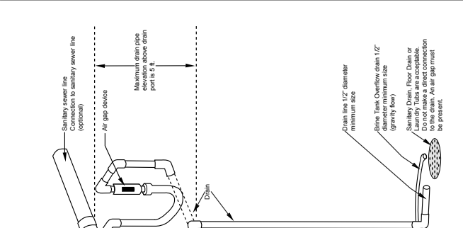
- Attach 1/2” drain line to drain elbow with insert and nut. Use optional 3/4” drain fittings if drain run exceeds 25 ft.
- Do not elevate the drain line over 5’ above the top of the valve (8’ on municipal systems) or to exceed 25’ in length at either height.
CAUTION: An air gap must be provided upon sewer entry. (Conform to local plumbing and sanitation codes and ordinances).
- The salt storage cabinet or brine tank provides an overflow. Attach 1/2” ID flexible plastic tubing to the overflow fitting and direct it to the drain. DO NOT connect to the main drain line. Use a separate gravity flow line.
Installation Procedures
All installation procedures must conform to local plumbing, electrical and sanitation codes and ordinances.
A. Planning Installation
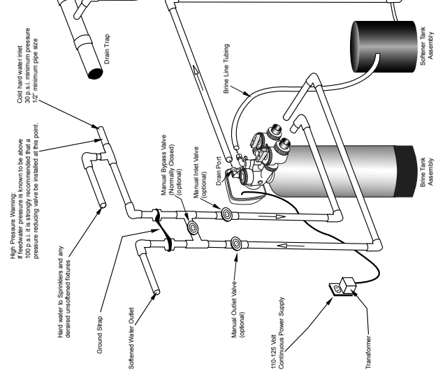
- It is recommended that outside faucets for lawn service be on a hard water line, ahead of the softener. This will conserve softened water, save salt and prevent lawn damage. If this is not practical, use the convenient integral bypass valve assembly during irrigation flows.
- CAUTION: The inlet water temperature MUST NOT EXCEED 110° F.
- DO NOT locate the softener where ambient temperature drops below 40° F.
- Allow space around the softener for ease of servicing.
- Softener drain lines must never be solidly connected to the sewer line (always provide an air gap at the END of the drain line).
- The drain line must NOT be elevated over 5’ from the top of the softener on well systems, and 8’ on municipal water systems.
- Drain line must not extend more than 20’ in length. If longer runs are required increase the drain size to 1”.
- The brine tank or salt storage cabinet is a gravity drain. This drain line must be lower than the drain fitting on the side wall of the brine tank or cabinet.
B. General Installation
- Turn off the main water supply before making any plumbing connections to existing piping.
- Move the softener into position, making sure it is on a clean level surface. If shims are needed you may use those to create a level installation. DO NOT USE METAL SHIMS
- When installing the unit, be sure to connect the inlet and outlet to the correct ports on the valve. The bypass valve and the control valve are both marked with arrows that indicate the direction of water flow. If water lines are reversed resin maybe forced from the water softener and into household plumbing system. Should this occur, the plumbing system would need to be flushed.
- Install the bypass valve assembly. The control valve is designed to accommodate minor plumbing misalignments. It is not designed to support the weight of the unit.
- Please see page 3, item 3 for assembling and soldering of fittings.
- Install an appropriate grounding strap across the inlet and outlet piping of the water conditioning system to ensure that a proper ground is maintained.
- Move the brine tank into place. Making sure that the floor is clean of any debris. Sharp objects such as rocks can cause punctures to the brine tank over a period of time. This would not be covered under Marlo’s warranty. (DO NOT ADD SALT AT THIS TIME).
- Connect one end of the brine line (brine line is located inside the brine tank. Marlo units come with 5’ of brine line) to the brine elbow of the brine tank and the other end to the brine elbow on the control valve. The brine elbow on the control valve is black in color and located on the top of the control valve. The brine elbow swivels to allow the brine tank to be placed in a convenient position.
- The drain line connector is located on the top of the control valve and is black in color. The water softener comes standard with 5/8 insert and nut if installer is using a poly tube. The drain elbow is threaded, so a 3⁄4” drain line may also be used. NOTE: If soldering the drain line use caution so as not to cause damage to the drain elbow.
- An overflow fitting is attached to the outside of the brine tank (overflow elbow is white in color). Attach a 5/8 drain line (do NOT connect overflow tubing with drain line tubing). The overflow fitting is installed in case the unit would malfunction and water would continually run to the brine tank. The overflow (if tubing is connected) would allow the excess water to be run to the drain rather than overflow onto the floor. Do NOT run overflow tubing above the overflow elbow at any point.
C. Installation and Start Up
- Make sure all connections have been made: Inlet, outlet, brine line installed and connected to the brine tank and control valve, drain line installed, and over flow drain tubing connected and run to the drain. (DO NOT CONNECT DRAIN LINE AND OVERFLOW TUBING)
- If the unit is not in bypass please do so now. If using a bypass purchased with the unit the unit will be in the bypass position when the two arrows on the handles of the bypass are pointing towards each other .
- Turn on your main water supply. Locate a cold soft water tap and turn it on, allow the water to run until all excess air and foreign material is removed from the water.
- Add seven (7) gallons of water to the brine tank.
- Plug the water softener into the designated receptacle. Program the current time of day.
- Press and hold the REGEN button (located in the upper right hand corner) until the unit starts a regeneration (depending on how the unit is programmed the first cycle may be back wash or brine fill). Once the piston stops moving and the unit is counting down press the REGEN key again. This will advance the unit to the next cycle. Repeat this process until you see the word RINSE in the upper left hand corner. Slowly open the inlet side of the bypass . Let the water run to the drain until the water runs clear.
- Place the bypass back into the bypass mode.
- Press the REGEN button again to cycle the unit to the next cycle. Wait for the piston to stop moving and press the REGEN button again. Repeat this until the unit is at the home screen. The home screen will be blue in color.
- Press and hold the REGEN button again until the unit starts a regeneration. Depending on how the unit it set up you might have to wait for the piston to stop moving and press the REGEN button again repeating several times till the word BACKWASH appears in the upper left hand corner. On most units BACKWASH should appear at the first screen.
- Slowly turn the handle of the incoming water until the bypass valve is completely opened. Once you have a solid flow of water to the drain, open the outlet side of the bypass to duplicate the normal operation.
- Press the REGEN button again to cycle the unit to the next cycle. Wait for the piston to stop moving and press the REGEN button again. Repeat this until the unit is at the home screen. The home screen will be blue in color.
- Set the incoming hardness of the water, time of regeneration and calendar override. through 6I.
- Add salt to brine tank.
D. Manual Regeneration
The user can initiate manual regeneration.
Pressing and holding the REGEN button for approximately 3 seconds will immediately start the regeneration. The user cannot cancel this request.
NOTE: Program Timer “Lockout” Feature
The Program Timer is initially set to allow access to all Programming, Diagnostic and History screens. The Installer can limit access to (lockout) most screens by activating the Lockout Feature.
Activating “Lockout” allows the user to view and change only Water Hardness, Days Override, Time of Regeneration and Time of day.
Activate “Lockout” Feature: Press DOWN then NEXT then UP then CLOCK in sequence. LOCK will briefly appear in the display.
De-activate “Lockout” Feature: Press DOWN then NEXT then UP then CLOCK. UNLOCK will briefly appear in the display.
When in operation normal user displays are time of day, gallons remaining, days remaining before regeneration, or current flow rate are shown. The user has the option to choose which screen is displayed by pressing the NEXT button. When stepping through a procedure if no buttons are pressed within five minutes the display returns to a normal user display. Any changes made prior to the five minute time out are incorporated. The one exception is current flow rate display under the diagnostic procedure. The current flow rate display has a 30 minute time out feature.
OPERATION
Control Valve Function and Cycles of Operation
This glass filled Noryl1
fully automatic control valve is designed as the primary control center to direct and regulate all cycles of a water softener or filter. When the control valve is set up as a softener, the control valve can be set to perform down flow or up flow regeneration with the proper piston. When the control valve is set up as a filter, the control valve can be set to perform down flow regeneration or simply backwash. The control valve can be set to regenerate on demand (consumption of a predetermined amount of water) and/or as a time clock (passage of a particular number of days). The control valve can be set so that the softener can meet the Water Quality Association (WQA) or NSF International efficiency rating.
The control valve is compatible with a variety of regenerants and resin cleaners. The control valve is capable of routing the flow of water in the necessary paths to regenerate or backwash water treatment systems. The injector regulates the flow of brine or other regenerants. The control valve regulates the flow rates for backwashing, rinsing and the replenishing of treated water into a regenerant tank, when applicable.
The control valve is designed to deliver high service (27 gpm @ 15 psig) and backwash (27 gpm @ 25 psig) flow rates when the bypass has straight fittings and a 1.050” distributor. The control valve uses no traditional fasteners (e.g. screws), instead clips, threaded caps, nuts and snap type latches are used. Caps and nuts only need to be firmly hand tightened because radial seals are used. Tools required to service the valve include one small blade screwdriver, pliers and a pair of hands. Disassembly for servicing takes much less time than comparable
products currently on the market. Control valve installation is made easy because the distributor tube can be cut 1/2” above to 1/2” below the top of the tank thread. The distributor tube is held in place by an o-ring seal and the control valve also has a bayonet lock feature for upper distributor baskets.
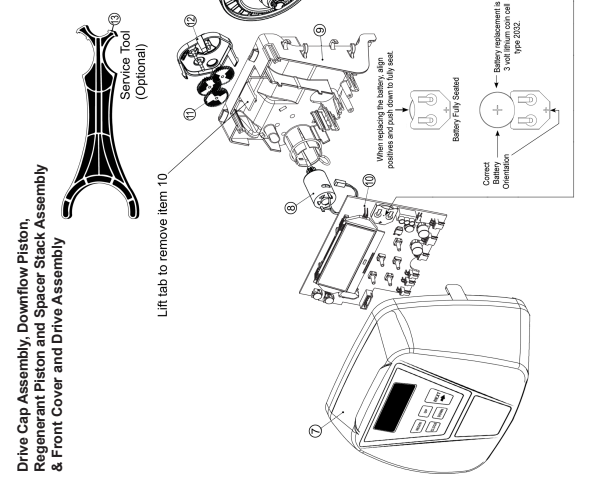
The transformer power pack comes with a 15-foot power cord and is designed for use with the control valve. The transformer power pack is for dry location use only. The control valve remembers all settings for up to 8 hours if the power goes out and the battery is not depleted. After 8 hours, the only item that needs to be reset is the time of day; other values are permanently stored in the nonvolitile memory. If a power loss lasts less than 8 hours and the time flashes on and off, the time of day should be reset and the non rechargeable battery should be replaced. The replacement battery is a commercially available 3 volt Lithium coin cell type 2032.
Table 3 shows the order of the cycles when the valve is set up as a softener. When the control valve is used as a down flow softener, two backwashes always occur. When the control valve is used as an up flow softener, only one backwash occurs after brining. The installer has the option of having the regenerant refill after the rinse cycle or have the regenerant prefill before regeneration. If the installer chooses to have the regenerant prefill before regeneration, the prefill starts two hours before the regeneration time set. During the 2-hour period in which the brine is being made, treated (softened) water is still available. For example: regeneration time = 2:00 A.M., prefill option selected, downflow softener. Fill occurs at 12:00 A.M., start of backwash cycle occurs at 2:00 A.M.
1 – Noryl is a trademark of General Electric
| Table 3 Regeneration Cycles |
| 1st Cycle: Backwash Normal |
| 2nd Cycle: Regenerate |
| 3rd Cycle: Backwash Normal |
| 5th Cycle: Rinse |
| 6th Cycle: Fill |
Installer Display Settings
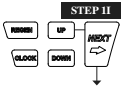
STEP 1I – Press NEXT and UP simultaneously for 3 seconds.
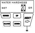
STEP 2I – Hardness: Set the amount of hardness in grains of hardness as calcium carbonate per gallon using DOWN or UP. The default is 20 with value ranges from 1 to 150 in 1 grain increments. Note: The grains per gallon can be increased if soluble iron needs to be reduced. This display will not show if “FILTERING” is selected in Step 2F or if ‘AUTO’ is not selected in Set Volume Capacity in OEM Softener System Setup. Press NEXT to go to step 3I. Press REGEN to exit Installer Display Settings.
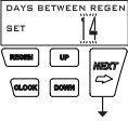
STEP 3I – Day Override: When volume capacity is set to “OFF”, sets the number of days between regenerations. When volume capacity is set to AUTO or to a number, sets the maximum number of days between regenerations. If value set to “OFF”, regeneration initiation is based solely on volume used. If value is set as a number (allowable range from 1 to 28) a regeneration initiation will be called for on that day even if suf cient volume of water were not used to call for a regeneration. Set Day Override using DOWN or UP:
• number of days between regeneration (1 to 28); or
• “OFF”.
Press NEXT to go to step 4I. Press REGEN to return to previous step.
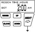
STEP 4I – Next Regeneration Time (hour): Set the hour of day for regeneration using DOWN or UP. AM/PM toggles after 12. The default time is 2:00 AM. This display will show “REGEN IMMEDIATE ON ZERO GAL” if “IMMEDIATE” is selected by the installer. Press NEXT to go to step 5I. Press REGEN to return to previous step.
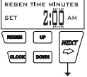
STEP 5I – Next Regeneration Time (minutes): Set the minutes of day for regeneration using DOWN or UP. This display will not be shown if “IMMEDIATE” was selected by the installer. Press NEXT to go to Step 6I. Press REGEN to return to previous step.
RETURN TO NORMAL MODE
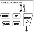
STEP 6I – Energy Saver operation. When set to OFF, the display backlight is always on. When set to ON, the display backlight will go off after 5 minutes of no keypad activity. A valve error or salt level alert will activate the display backlight, and prevent deactivation until the error or alert is reset by the user. Press NEXT to exit Installer Display Settings. Press REGEN to return to the previous step.
User Display Settings
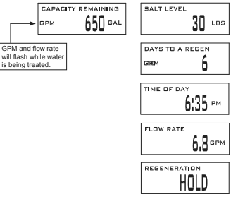
When the system is operating, several displays may be shown. Pressing NEXT will alternate between the displays. One of the displays is the current time of day. CAPACITY REMAINING is the gallons that will be treated before the system goes through a regeneration cycle. Pressing DOWN while in the Capacity Remaining display will decrease the capacity remaining in 10 gallon increments and will also increase the volume used impacting the recorded values in Diagnostics Steps 3D, 4D and 5D and Valve History, Step 4VH. DAYS TO A REGEN is the number of days left before the system goes through a regeneration cycle. Pressing UP or DOWN while in this screen will temporarily increase or decrease the displayed value by 1 day. Another display shows the current treated water flow rate through the system. Contact information will be displayed if it was edited. For concerns with phone number or banner text displays, contact OEM for instructions. The fifth display will show either DP or HOLD if the dP switch is closed. If the system has called for a regeneration that will occur at the pre-set time of regeneration, the words REGEN TODAY will alternate with the header on the display. If a water meter is installed, GPM ashes (and alternates with the ow rate) on the display when water is being treated (i.e. water is owing through the system). If Salt Level Monitor has
been set to ON in Step 16S, the Salt Level screen will appear. To adjust the salt level, press CLOCK, and use UP or DOWN to set the current value. The salt level is adjustable from 0 to 500 lbs. in 10 lb. increments.
NOTE: SALT LEVEL screen only appears if programmed.
REGEN PENDING will be displayed in Alternator Systems whenever a unit is waiting to initiate the first cycle step of regeneration.

STAND BY will be displayed in Alternator Systems when a valve is in Standby state.

DELAYED RINSE+FILL PENDING will be displayed whenever a zero-capacity tank has transferred to an off-line state and is currently waiting to initiate the second portion of a regeneration cycle. Viewed only when Delayed Rinse and Fill is set to ON.

Regeneration Mode
Typically a system is set to regenerate at a time of low water usage. An example of a time with low water usage is when a household is asleep. If there is a demand for water when the system is regenerating, untreated water will be used.

When the system begins to regenerate, the display will change to include information about the step of the regeneration process and the time remaining for that step to be completed. The system runs through the steps automatically and will reset itself to provide treated water when the regeneration has been completed.
Manual Regeneration
Sometimes there is a need to regenerate the system sooner than when the system calls for it, usually referred to as manual regeneration. There may be a period of heavy water usage because of guests or a heavy laundry day.

To initiate a manual regeneration at the preset delayed regeneration time, when the regeneration time option is set to “DELAYED REGEN” or “DELAY + IMMEDIATE”, press and release “REGEN”. The words “REGEN TODAY” will periodically be shown on the display to indicate that the system will regenerate at the preset delayed regeneration time. If you pressed the “REGEN” button in error, pressing the button again will cancel the request. Note: If the regeneration time option is set to “IMMEDIATE” there is no set delayed regeneration time so “REGEN TODAY” will not activate if “REGEN” button is pressed.
To initiate a manual regeneration immediately, press and hold the “REGEN” button for three seconds. The system will begin to regenerate immediately. The request cannot be cancelled.
Note: For softeners, if brine tank does not contain salt, ll with salt and wait at least two hours before regenerating.
Set Time of Day
The user can also set the time of day. Time of day should only need to be set if the battery has been depleted because of extended
power outages or when daylight saving time begins or ends. If an extended power outage occurs, the time of day will flash on and off which indicates the time of day should be reset. The non rechargeable battery should also be replaced.
STEP 1U – Press CLOCK.
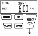
STEP 2U – Current Time (hour): Set the hour of the day using DOWN or UP. AM/PM toggles after12. Press NEXT to go to Step 3U.
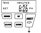
STEP 3U – Current Time (minutes): Set the minutes of the day using DOWN or UP. Press NEXT to exit Set Time of Day. Press REGEN to return to previous step.
RETURN TO NORMAL MODE
Power Loss
If the power goes out the system will keep time until the battery is depleted. If an extended power outage occurs, the time of day will ash on and off which indicates the time of day should be reset and the non rechargeable battery replaced. The system will remember the rest.
Error Message
If the word “ERROR” and a number are displayed contact the Installer for help. This indicates that the valve was not able to function
properly. If the number and banner text in the Contact Screens has been edited, the two displays below will alternate.

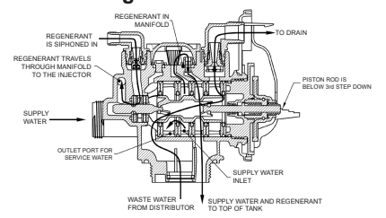
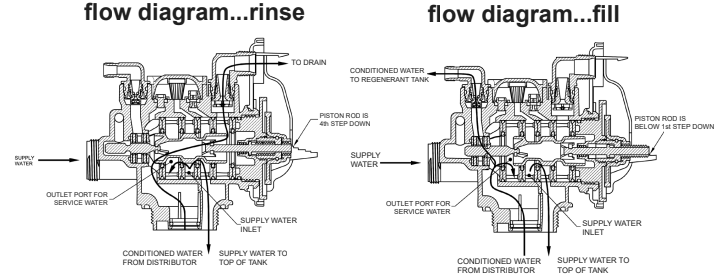
FLOW DIAGRAMS
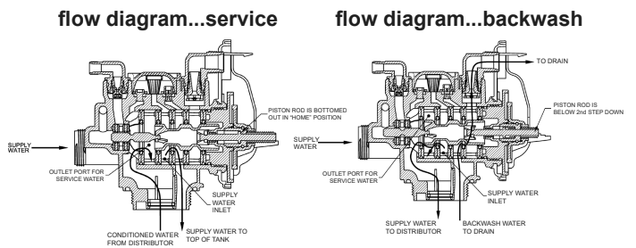
flow diagram…downflow brine
Bypass Valve
The bypass valve is typically used to isolate the control valve from the plumbing system’s water pressure in order to perform control valve repairs or maintenance. The WS1 bypass valve is particularly unique in the water treatment industry due to its versatility and state of the art design features. The 1” full flow bypass valve incorporates four positions including a diagnostic position that allows service personal to work on a pressurized system while still providing untreated bypass water to the facility or residence. Its completely non-metallic, all plastic, design allows for easy access and serviceability without the need for tools.
The bypass body and rotors are glass filled Noryl and the nuts and caps are glass filled polypropylene. All seals are self-lubricating EPDM to help prevent valve seizing after long periods of non-use. Internal o-rings can easily be replaced if service is required.
The bypass consists of two interchangeable plug valves that are operated independently by red arrow shaped handles. The handles identify the flow direction of the water. The plug valves enable the bypass valve to operate in four positions.
NORMAL OPERATION
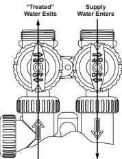
Normal Operation: The inlet and outlet handles point in the direction of flow indicated by the engraved arrows on the control valve. Water flows through the control valve during normal operation and this position also allows the control valve to isolate the media bed during the regeneration cycle.
BYPASS OPERATION
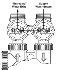
Bypass: The inlet and outlet handles point to the center of the bypass, the control valve is isolated from the water pressure contained in the plumbing system. Untreated water is supplied to the plumbing system.
DIAGNOSTIC MODE
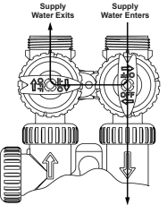
Diagnostic: The inlet handle points in the direction of flow and the outlet handle points to the center of bypass valve, system water pressure is allowed to the control valve and the plumbing system while not allowing water to exit from the control valve to the plumbing.
SHUT OFF MODE
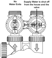
Shut Off: The inlet handle points to the center of the bypass valve and the outlet handle points in the direction of flow, the water is shut off to the plumbing system. If water is available on the outlet side of the softener it is an indication of water bypass around the system (i.e. a plumbing connection somewhere in the building bypasses the system).
MAINTENANCE
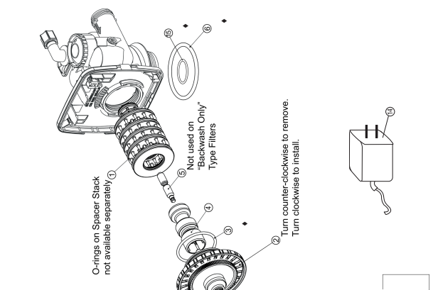
Drive Cap Assembly, Downflow Piston, Upflow Piston, Regenerant Piston and Spacer Stack Assembly
| Item No. | Part No. | Description | Quantity |
| 1 | A2466034 | *Spacer Stack Assembly w/o o-rings | 1 |
| 2 | A2080077 | Drive Cap Assembly | 1 |
| 3 | B1213022 | O-Ring 228 (use Valve O-ring Kit) | 1 |
| 4 | A2309040 | Piston Downflow Assembly | 1 |
| 5 | A2438033 | Regenerant Piston | 1 |
| 6 | B1213022 | O-Ring 337 (use Valve O-ring Kit) | 1 |
| 15 | B1213022 | O-Ring 215 (use Valve O-ring Kit) | 1 |
Item #4 identified with “DN” code.
Item #5 not used with Backwash Only filter applications.
Front Cover and Drive Assembly
| Item No. | Part No. | Description | Quantity |
| 7 | A2103160 | Front Cover ASSY V3948-01 | 1 |
| 8 | A2085050 | Motor | 1 |
| 9 | A2328046 | Drive Bracket & Spring Clip | 1 |
| 10 | A2341033 | PC Board V3955MA-BOARD | 1 |
| 11 | A2393046 | Drive Gear 12 x 36 | 3 |
| 12 | A2103132 | Drive Gear Cover | 1 |
| 13 | A2491086 | Service Tool | 1 |
| 14 | A2242054 | Transformer 110V – 12V | 1 |
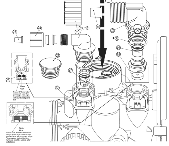
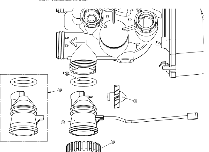
Injector Cap, Injector Screen, Injector, Plug , O-Ring, Refill and Refill Port Plug, &Drain Line – 3/4”
Part of Kit, O-ring (Item #51,

Injector Cap, Injector Screen, Injector, Plug and O-Ring
| Item No. | Part No. | Description | Quantity | |
| 16 | A2080079 | Injector Cap | 1 | |
| 17 | Use Item 51 | O-Ring 135 (Use Valve O-ring Kit) | 1 | |
| 18 | A2142016 | Injector Screen | 1 | |
| 19 | A2079059 | Injector Assembly Z Plug | See note | 1 |
| 20 | A2079060 | Injector Assembly A Black | ||
| A2079048 | Injector Assembly B Brown | |||
| A2079046 | Injector Assembly C Violet | |||
| A2079045 | Injector Assembly D Red | |||
| A2079049 | Injector Assembly E White | 1 | ||
| A2079047 | Injector Assembly F Blue | |||
| A2079050 | Injector Assembly G Yellow | |||
| A2079055 | Injector Assembly H Green | |||
| A2079062 | Injector Assembly I Orange | |||
| A2079063 | Injector Assembly J Light Blue | |||
| A2079064 | Injector Assembly K Light Green |
*The injector plug and the injector each contain one 011 (lower) and 013 (upper) o-ring. Note: For downflow brine, injector is located in the down hole and injector plug in the up hole. For a filter that only backwashes injector plugs are located in both holes.
Refill and Refill Port Plug
| Drawing No. | Order No. | Description | Quantity |
| 21 | A2287059 | Refill Port Plug Assembly | This part is required for backwash only systems |
| 22 | A2411015 | Elbow Locking Clip | 1 |
| 23 | A2409016 | Polytube insert 3/8 | 1 |
| 24 | A2095071 | Nut 3/8 | 1 |
| 25a | A2080078 | Elbow Cap 3/8 | (use w/ 3/8” tubing) 1 |
| 25b | A2129100 | Elbow 1/2” with nut and insert | (use w/ 1/2” tubing) Option |
| 26 | Use Item 51 | O-Ring 019 (Use Valve O-ring Kit) | 1 |
| 27 | A2104033 | RFC Retainer Assembly* | 1 |
| 28 | A2253108 | RFC Retainer Assembly* | 1 |
*Assembly includes RFC.
Drain Line – 3/4”
| Drawing No. | Order No. | Description | Quantity |
| 29 | A2411015 | Elbow Locking Clip | 1 |
| 30 | A2409013 | Polytube insert 5/8 | Option |
| 31 | A2095065 | Nut 3/4 Drain Elbow | Option |
| 32 | A2099056 | Drain Elbow 3/4 Male Assembly | 1 |
| 33 | Use Item 51 | O-Ring 019 (Use Valve O-ring Kit) | 1 |
| 34 | A2104034 | Drain Flow Washer Retainer Assembly | 1 |
| 35 | A2253114 A2253099 A2253084 A2253083 A2253081 A2253082 A2253085 A2253086 A2253087 | Drain Flow Washer 0.7 gpm for 3/4 Drain Flow Washer 1.0 gpm for 3/4 Drain Flow Washer 1.3 gpm for 3/4 Drain Flow Washer 1.7 gpm for 3/4 Drain Flow Washer 2.2 gpm for 3/4 Drain Flow Washer 2.7 gpm for 3/4 Drain Flow Washer 3.2 gpm for 3/4 Drain Flow Washer 4.2 gpm for 3/4 Drain Flow Washer 5.3 gpm for 3/4 |
“MCV” Series
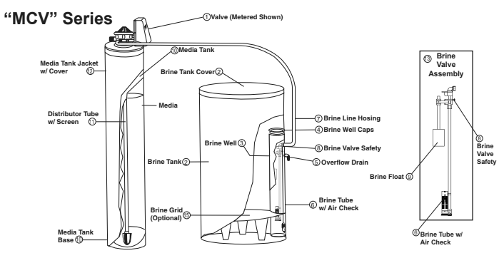
| PARTS LISTING | ||
| Part Number | No. | Description |
| Contact Factory | 1 | Valve Metered (Complete – Specify Model) |
| A2042018 | 2 | Brine Tank w/ Cover |
| A2071005 | 3 | Brine Well |
| A2072003 | 4 | Brine Well Cap |
| A2250003 | 5 | A2250003 |
| A2250003 | 6 | Brine Tube w/ Air Check |
| B1020001 | 7 | Brine Line Hose w/ Inserts |
| A2005058 | 8 | Brine Valve Safety |
| A2107022 | 9 | Brine Float |
| A2126201 | 10 | Media Tank – MCV-22K (8” x 44”) |
| A2126203 | 10 | Media Tank – MCV-30K (9” x 48”) |
| A2126205 | 10 | Media Tank – MCV-40K + Combo (10” x 47”) |
| A2126206 | 10 | Media Tank – MCV-45K (10” x 54”) |
| A2126208 | 10 | Media Tank – MCV-60K (12” x 52”) |
| A2255101 | 10 | Media Tank – MCV-22KC |
| A2255102 | 10 | Media Tank – MCV-30KC |
| B1023056 | 11 | Distributor Tube Assembly |
| Contact Factory | 12 | Media Tank Jacket w/ cover – Optional |
| B1017003 | 13 | Brine Valve Assembly – Complete – Includes #6. #8, & #9 |
| A2284002 | 15 | Grid (Optional) |
| A2121047 | 16 | Media (Specify Model) |
Water Meter and Meter Plug
| Item No. | Part No. | Description | Quantity |
| 36 | A2095069 | Nut 1” Quick Connect | 1 |
| *37 | A2360039 | Meter Assembly | 1 |
| 38 | A2100027 | Turbine Assembly | 1 |
| 39 | A2100027 | O-Ring 215 (Use Valve O-ring Kit) | 1 |
| 40 | A2287077 | Meter Plug Assembly (Time clock option) | 1 |
*Item #37 includes Items #38 & #39.
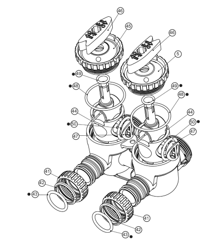
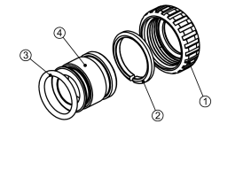
| Item No. | Part No. | Description | Quantity |
| 41 | A2095069 | Nut 1” Quick Connect | 2 |
| 42 | A2453012 | Split Ring | 2 |
| 43 | use item 52 | O-Ring 215 (Kit available – see Item #10) | 2 |
| 44 | A2607004 | Bypass 1” Rotor | 2 |
| 45 | A2080090 | Bypass Cap | 2 |
| 46 | A2395009 | Bypass Handle | 2 |
| 47 | A2104036 | Bypass Rotor Seal Retainer | 2 |
| 48 | use item 52 | O-Ring 135 (use Bypass Valve Kit) | 2 |
| 49 | use item 52 | O-Ring 112 (use Bypass Valve Kit) | 2 |
| 50 | use item 52 | O-Ring 214 (use Bypass Valve Kit) | 2 |
Part of Kit, O-ring By-Pass(Item 52)
Valve O-ring Kit
| 51 | B1213022 | KIT O-ring (contains 1 each of 3, 6, 15, 17, 26, & 33) | 1 per valve |
Bypass Valve O-ring Kit
| 52 | B1213021 | KIT O-ring Bypass (Incl. 2 ea. of items 43,48,49,& 50) | 1 per valve |
(Not Shown) Description Bypass Vertical Adapter Assembly
Order No: A2129080 (Optional)
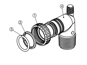
Description: Fitting 1” PVC Male NPT Elbow Assembly
| Drawing No. | Order No. | Description | Quantity |
| 1 | A2095069 | Nut 1” Quick Connect | 2 |
| 2 | A2453012 | Split Ring | 2 |
| 3 | A2077178 | O-Ring 215 | 2 |
| 4 | A2129101 | Fitting 1”PVCMaleNPT Elbow | 2 |
Order No: A2099054 (Optional)
Description: Fitting 3/4” & 1” PVC Solvent 900 Asy
| Drawing No. | Order No. | Description | Quantity |
| 1 | A2095069 | Nut 1” Quick Connect | 2 |
| 2 | A2453012 | Split Ring | 2 |
| 3 | A2077178 | O-Ring 215 | 2 |
| 4 | A2569008 | Fitting 3/4&1 PVC Solvent 90 | 2 |
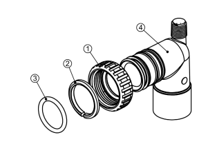
Order No: A2435068 (Standard)
Description: Fitting 1” Brass Sweat Assembly
| Drawing No. | Order No. | Description | Quantity |
| 1 | A2095069 | Nut 1” Quick Connect | 2 |
| 2 | A2453012 | Split Ring | 2 |
| 3 | A2077178 | O-Ring 215 | 2 |
| 4 | A2569006 | Fitting 1” Brass Sweat | 2 |
Order No: A2435072 (Optional)
Description: Fitting 3/4” Brass Sweat Assembly
| Drawing No. | Order No. | Description | Quantity |
| 1 | A2095069 | Nut 1” Quick Connect | 2 |
| 2 | A2453012 | Split Ring | 2 |
| 3 | A2077178 | O-Ring 215 | 2 |
| 4 | A2569008 | Fitting 3/4&1 PVC Solvent 90 | 2 |
READ ALSO: MACCLEAN NS/NLS SERIES RESIDENTIAL WATER SOFTENER USER’S MANUAL
Troubleshooting Procedures
| Problem | Possible Cause | Solution |
| 1.Timer does not display time of day | a. Transformer unplugged b. No electric power at outlet c. Defective transformer d. Defective PC board | a. Connect power b. Repair outlet or use working outlet c. Replace transformer d. Replace PC board |
| 2.Timer does not display correct time of day | a. Switched outlet b. Power outage c. Defective PC board | a. Use uninterrupted outlet b. Reset time of day c. Replace PC board a. Put bypass valve in service position |
| 3.No softening/filtering display when water is flowing | a. Bypass valve in bypass position b. Meter connection disconnected c. Restricted/stalled meter turbine d. Defective meter e. Defective PC board | a. Put bypass valve in service position b. Connect meter to PC board c. Remove meter and check for rotation or foreign material d. Replace meter e. Replace PC board |
| 4.Control valve regenerates at wrong time of day | a. Power outages b. Time of day not set correctly c. Time of regeneration incorrect d. Control valve set at “on 0” (immediate regeneration) e. Control valve set at NORMAL + on | a. Reset control valve to correct time of day b. Reset to correct time of day (a.m./p.m.) c. Reset regeneration time (a.m./p.m.) d. Check control valve set-up procedure regeneration time option e. Check control. valve set-up procedure regeneration time option |
| 5.Display screen will turn red and flash the Installer’s Name and phone number to call for service. ERROR followed by code number 101 Error Code – Unable to recognize start of regeneration 102 Error Code – Unexpected stall 103 Error Code – Motor ran to long, timed out trying to reach next cycle position 104 Error Code – Motor ran to long, timed out trying to reach home position If other Error Codes display contact the factory ERROR Reset Procedure: Correct error condition. Press NEXT and REGEN simultaneously for three seconds. | a. Control valve has just been ser- viced b. Foreign matter is lodged in control valve c. High drive forces on piston d. Control valve piston not in home position e. Motor not inserted fully to engage pinion, motor wires broken or disconnected, motor failure f. Drive gear label dirty or damaged, missing or broken gear g. Drive bracket incorrectly aligned to back plate h. PC board is damaged or defective i. PC board incorrectly aligned to drive bracket | a. Press NEXT and REGEN for 3 seconds or unplug power source jack (black wire) and plug back in to reset control valve b. Check piston and spacer stack assembly for foreign matter c. Replace piston(s) and spacer stack assembly d. Press NEXT and REGEN for 3 seconds or unplug power source jack (black wire) and plug back in to reset control valve e. Check motor and wiring. Replace motor if necessary f. Replace or clean drive gear(s) g. Reseat drive bracket properly h. Replace PC board i. Ensure PC board is correctly snapped on to drive bracket |
| 6.Control valve stalled in regeneration | a. Motor not operating b. No electric power at outlet c. Defective transformer d. Defective PC board e. Broken drive gear or drive cap assembly f. Broken piston retainer g. Broken main or regenerant piston | a. Replace motor b. Repair outlet or use working outlet c. Replace transformer d. Replace PC board e. Replace drive gear or drive cap as- sembly f. Replace drive cap assembly g. Replace main or regenerant piston |
| 7.Control valve does not regenerate automatically when REGEN button is depressed and held | a. Transformer unplugged b. No electric power at outlet c. Broken drive gear or drive cap assembly d. Defective PC board | a. Transformer unplugged b. No electric power at outlet c. Broken drive gear or drive cap assembly d. Defective PC board |
| 8.Control valve does not regenerate automatically but does when REGEN button is depressed | a. By-pass valve in bypass position b. Meter connection disconnected c. Restricted/stalled meter turbine d. Defective meter e. Defective PC board f. Set-up error | a. Put control valve in service position b. Connect meter to PC board c. Remove meter and check for rotation or foreign material d. Replace meter e. Replace PC board f. Check control valve set-up procedure |
| 9 Time of day flashes on and off | a. Power has been out more than two hours, the transformer was unplugged and then plugged back into the wall outlet, the transformer plug was unplugged and then plugged back into the board or the NEXT and REGEN buttons were pressed to reset the valve. | a.. Reset the time of day |
You can download the PDF version of the MARLO INCORPORATED WATER SOFTENER USER’S MANUAL here.