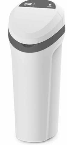
How to install, operate and maintain your Demand Controlled Water Softener
Do not return water softener to store
If you have any questions or concerns when installing, operating or maintaining your water softener, call our toll free number:
1-888-64 WATER
(1-888-649-2837)
or visit www.mortonwatersofteners.com When you call, please be prepared to provide the model and serial number of your product,
found on the rating decal, located on the rim below the salt lid hinges.
Systems tested and certified by NSF International against NSF/ANSI Standard 44 for hardness reduction and efficiency, and certified to NSF/ANSI Standard 372.
For best results use Morton® Clean and Protect® or Morton® Clean and Protect® Plus Rust Defense® Pellets in your water softener.
Protect your new water softener with Morton® Clean and Protect® or Morton® Clean and Protect® Plus Rust Defense® Pellets
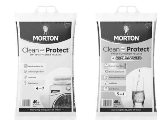
Morton® Water Softener Salt Pellets are made with a time-release formula that works with your softener to help prevent mineral buildup
and keep your home’s pipes and appliances working at their best. Whether you’re looking to remove iron and fight buildup, or extend your
water softener’s life, Morton® has the right salt for you. Use one or both of our premium formula pellets in any water softener for the best results.
Remember to fill your water softener with Morton® America’s #1 Brand of Water Softener Salt!
READ ALSO: MARLO INCORPORATED WATER SOFTENER INSTALLATION, OPERATION, AND MAINTENANCE MANUAL (MCV Series)
Inspect Shipment
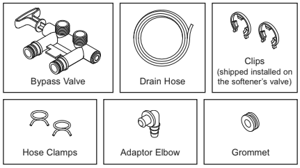
The parts required to assemble and install the unit are included in a bag. Thoroughly check the water softener for possible shipping damage and parts loss. Also inspect and note any damage to the shipping carton.
Remove and discard (or recycle) all packing materials. To avoid loss of small parts, we suggest you keep the small parts in the parts bag until you are ready to use them.
Packing List
Do not return the water softener to store.
If you have any questions, or there are missing parts or damage, please call Toll Free 1-888-64WATER (1-888-649-2837). When you call, please be prepared to provide the model and serial number of your product, found on the rating decal, located on the rim below the salt lid hinges. For more installation or service information, visit www.mortonwatersofteners.com.
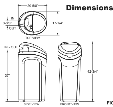
Dimensions
Specifications & Performance Claims
| Model M20 | Model M27 | Models M30 & MC30 | Model M34 | |
| Model Code | o20 | o27 | o30 | o34 |
| Regeneration Control | Demand | Demand | Demand | Demand |
| Rated Softening Capacity (Grains @ Salt Dose) | 9,310 @ 1.8 lbs. 18,000 @ 5.8 lbs. 21,500 @ 9.7 lbs. | 11,100 @ 2.2 lbs. 23,700 @ 7.0 lbs. 28,100 @ 11.2 lbs. | 13,200 @ 2.9 lbs. 25,500 @ 8.0 lbs. 30,000 @ 13.1 lbs. | 13,700 @ 2.7 lbs. 29,200 @ 8.6 lbs. 34,900 @ 14.5 lbs. |
| Rated Efficiency (Grains/Pound of Salt @ Minimum Salt Dose) | 5,000 @ 1.8 lbs. | 5,040 @ 2.2 lbs. | 4,567 @ 2.9 lbs. | 5,060 @ 2.7 lbs. |
| Water Used During Regeneration @ Minimum Salt Dose | 2.9 gallons / 1,000 grains | 2.5 gallons / 1,000 grains | 2.8 gallons / 1,000 grains | 2.3 gallons / 1,000 grains |
| Total Water Used Per Regeneration @ Maximum Salt Dose | 26.2 gallons | 26.7 gallons | 33.6 gallons | 31.6 gallons |
| Rated Service Flow Rate | 6.5 gpm | 6.5 gpm | 7.0 gpm | 7.8 gpm |
| Amount of High Capacity Ion Exchange Resin | .61 cu. ft. | .73 cu. ft. | .82 cu. ft. | .91 cu. ft. |
| Pressure Drop at Rated Service Flow | 11.3 psig | 12.1 psig | 11.9 psig | 14.7 psig |
| Water Supply Max. Hardness | 95 gpg | 95 gpg | 95 gpg | 110 gpg |
| Water Supply Max. Clear Water Iron | 6 ppm* | 7 ppm* | 7 ppm* | 9 ppm* |
| Water Pressure Limits (min. / max.) | 20 – 125 psi** | |||
| Water Temperature Limits (min. / max.) | 40 – 120 °F | |||
| Minimum Water Supply Flow Rate | 3 gpm | |||
| Maximum Drain Flow Rate | 2.2 gpm |
*Capacity to reduce clear water iron is substantiated by laboratory test data. State of Wisconsin requires additional treatment if water supply contains clear water iron exceeding 5 ppm.
These systems conform to NSF/ANSI 44 for the specific performance claims as verified and substantiated by test data.
The efficiency rating is only valid at the stated salt dose. These softeners were efficiency rated according to NSF/ANSI Standard 44.
Variable Salt Dose: The salt dose is selected by the electronic controls at regeneration time based on the amount needed.
These softeners conform to NSF/ANSI 44 for the specific performance claims as verified and substantiated by test data. These models are efficiency rated. The efficiency rating is valid only at the stated salt dose. They have a demand initiated regeneration (D.I.R.) feature that complies with specific performance specifications intended to minimize the amount of regenerant brine and water used in their operation. Efficiency rated softeners have a rated salt efficiency of not less than 3,350 grains of total hardness exchange per pound of salt (based on sodium chloride) and shall not deliver more salt or be operated at a sustained maximum service flow rate greater than its listed rating.
The rated salt efficiency is measured by laboratory tests described in NSF/ANSI Standard 44. These tests represent the maximum possible efficiency that the system can achieve. Operational efficiency is the actual efficiency after the system has been installed. It is typically less than the efficiency due to individual application factors including water hardness, water usage, and other contaminants that reduce the softener’s capacity. These systems are not intended for treating water that is microbiologically unsafe or of unknown quality without adequate disinfection before or after the systems. For best results use clean grades of water softener salt. Refer to warranty and elsewhere in this manual for further details on installation and maintenance, parts and service, user responsibility, and further restrictions, or limitations to the use of the product.
In the state of California: You must turn the Salt Efficiency Feature setting to ON. This may initiate more frequent recharges. However, it will operate at 4,000 grains per pound of salt or higher. To turn on the Salt Efficiency Feature, follow the instructions in the “Salt Efficiency” section of this manual.
Before You Start
- The water softener requires a minimum water flow of 3 gallons per minute at the inlet. Maximum allowable inlet water pressure is 125 psi. If daytime pressure is over 80 psi, nighttime pressure may exceed the maximum. Use a pressure reducing valve if necessary (Adding a pressure reducing valve may reduce the flow). If your home is equipped with a back flow preventer, an expansion tank must be installed in accordance with local codes and laws.
- The water softener works on 24V DC electrical power, supplied by a direct plug-in power supply (included). Be sure to use the included power supply and plug it into a nominal 120V, 60 Hz household outlet that is in a dry location only, grounded and properly protected by an overcurrent device such as a circuit breaker or fuse.
- Do not use this system to treat water that is microbiologically unsafe or of unknown quality without adequate disinfection upstream or downstream of the system.
European Directive 2002/96/EC requires all electrical and electronic equipment to be disposed of according to Waste Electrical and Electronic Equipment (WEEE) requirements. This directive or similar laws are in place nationally and can vary from region to region. Please refer to your state and local laws for proper disposal of this equipment.
Water Treatment Information
Iron
Iron in water can cause stains on clothing and plumbing fixtures. It can negatively affect the taste of food, drinking water, and other beverages. Iron in water is measured in parts per million (ppm). The total* ppm of iron, and type or types*, is determined by chemical
analysis. Four different types of iron in water are:
- Ferrous (clear water) iron
- Ferric (red water) iron
- Bacterial and organically bound iron
- Colloidal and inorganically bound iron (ferrous or ferric)
Ferrous (clear water) iron is soluble and dissolves in water. This water softener will reduce moderate amounts of this type of iron (see specifications).** Ferrous (clear water) iron is usually detected by taking a sample of water in a clear bottle or glass. Immediately after taking, the sample is clear. As the water sample stands, it gradually clouds and turns slightly yellow or brown as air oxidizes the iron. This
usually occurs in 15 to 30 minutes.
When using the softener to reduce Ferrous (clear water) iron, add 5 grains to the hardness setting for every 1 ppm of Ferrous (clear water) iron. See “Set Water Hardness Number” section. Ferric (red water), and bacterial and organically bound irons are insoluble. This water softener will not remove ferric or bacterial iron. This iron is visible immediately when drawn from a faucet because it has oxidized before reaching the home. It appears as small cloudy yellow, orange, or reddish suspended particles. After the water stands for a period of time,
the particles settle to the bottom of the container. Generally these irons are removed from water by filtration. Chlorination is also recommended for bacterial iron.
Colloidal and inorganically bound iron is of ferric or ferrous form that will not filter or exchange out of water. This water softener will not remove colloidal iron. In some instances, treatment may improve colloidal iron water. Colloidal iron water usually has a yellow
appearance when drawn. After standing for several hours, the color persists and the iron does not settle, but remains suspended in the water.
Sediment
Sediment is fine, foreign material particles suspended in water. This material is most often clay or silt. Extreme amounts of sediment may give the water a cloudy appearance, and may require a sediment filter be installed upstream of the water softener.
* Water may contain one or more of the four types of iron and any combination of these. Total iron is the sum of the contents.
** Capacity to reduce clear water iron is substantiated by laboratory test data.
Installation Requirements
Location Requirements
Consider all of the following when selecting an installation location for the water softener.
- Do not locate the water softener where freezing temperatures occur. Do not attempt to treat water over 120oF. Freezing temperatures or hot water damage voids the warranty.
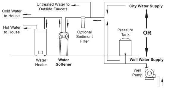
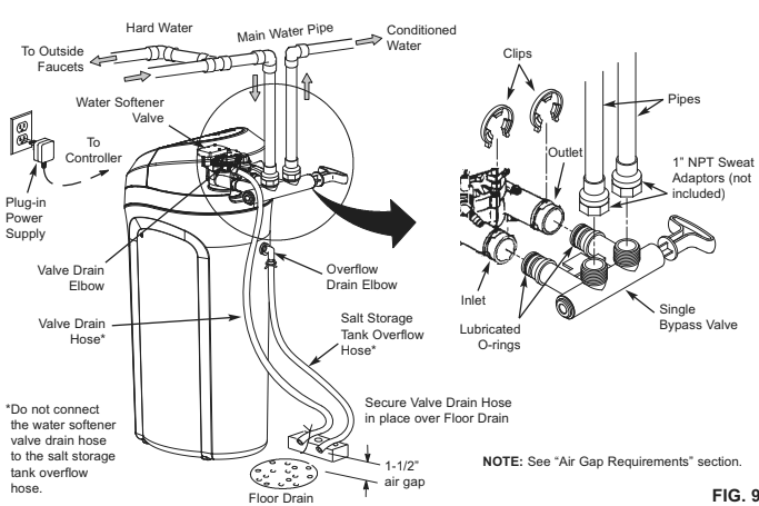
- To condition all water in the home, install the water softener close to the water supply inlet, and upstream of all other plumbing connections, except outside water pipes. Outside faucets should remain on hard water to avoid wasting conditioned water and salt.
- A nearby drain is needed to carry away regeneration discharge (drain) water. Use a floor drain, laundry tub, sump, standpipe, or other options (check your local codes). See “Air Gap Requirements” and “Valve Drain Requirements” sections.
- The water softener works on 24V DC electrical power, supplied by a direct plug-in power supply (included). Provide nearby a 120V, 60Hz electrical outlet in accordance with NEC and local codes.
- Always install the water softener between the water inlet and water heater. Any other installed water conditioning equipment should be installed between the water inlet and water softener (See Figure 4 below).
- Avoid installing in direct sunlight. Excessive sun heat may cause distortion or other damage to non-metallic parts.
Plumbing Codes
All plumbing must be completed in accordance with national, state and local plumbing codes.
In the state of Massachusetts: The Commonwealth of Massachusetts plumbing code 248-CMR shall be adhered to. A licensed plumber shall be used for this installation.
Air Gap Requirements
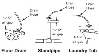
A drain is needed for the water discharged from the valve during the softener’s regeneration cycle (See Figure 3). A floor drain, close to the water softener, is preferred. A laundry tub, standpipe, etc. are other drain options. Secure valve drain hose in place. Leave an air gap of 1-1/2” between the end of the hose and the drain. This gap is needed to prevent backflow of sewer water into the water softener. Do not put the end of the drain hose into the drain.
The Proper Order To Install Water Treatment Equipment
Installation Requirements
Valve Drain Requirements
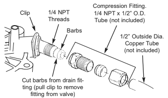
Using the flexible drain hose (included), measure and cut to the length needed. Flexible drain hose is not allowed in all localities (check your plumbing codes). If local codes do not allow use of a flexible drain hose, a rigid valve drain run must be used. Purchase a compression fitting (1/4 NPT x 1/2 in. minimum tube) and 1/2″ tubing from your local hardware store. Plumb a rigid drain as needed (See Figure 6).
NOTE: Avoid drain hose runs longer than 30 feet. Avoid elevating the hose more than 8 feet above the floor. Make the valve drain line as
short and direct as possible.
Inlet / Outlet Plumbing Options
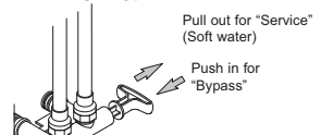
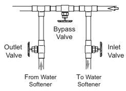
Always install either a single bypass valve (provided), as shown in Figure 7, or, if desired, parts for a 3 valve bypass system (not included) can be purchased and assembled, as shown in Figure 8. Bypass valves allow you to turn off water to the softener for maintenance if needed, but still have water in house pipes.
Use:
- Copper pipe
- Threaded pipe
- PEX (Crosslinked Polyethylene) pipe
- CPVC plastic pipe
- Other pipe approved for use with potable water
IMPORTANT: Do not solder with plumbing attached to the single bypass valve. Soldering heat will damage the plastic valve.
Single Bypass Valve
3 Valve Bypass
Installation Instructions
Typical Installation
Step 1. Turn Off Water Supply
- Close the main water supply valve, located near the well pump or water meter.
- Shut off the electric or fuel supply to the water heater.
- Open all faucets to drain all water from house pipes.
NOTE: Be sure not to drain water from the water heater, as damage to the water heater elements could result.
Step 2. Assembly
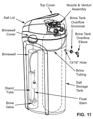
- Morton® water softener models are factory assembled. During installation, unsnap and remove the top cover, together with the salt lid, to expose the softener valve assembly. Set them aside to prevent damage. Check the brinewell to be sure it is secured and vertical (See Figure 11).
- Lift the brine valve out of the brinewell. Make sure the float stem is parallel to the stand tube so the seals will seat properly during operation. Place the brine valve back into the bottom of the brinewell and reinstall the brinewell cover.
- Install the brine tank overflow grommet and elbow into the 13/16” diameter hole in the back of the salt storage tank wall.
Step 3. Move the Unit into Place
- Move the water softener into the desired location. Set it on a solid, level surface.
IMPORTANT: Do not place shims directly under the salt storage tank to level the softener. The weight of the tank, when full of water and salt, may cause the tank to fracture at the shim.
- Visually check and remove any debris from the water softener valve inlet and outlet ports. Carefully remove the two large plastic clips (you will use them).
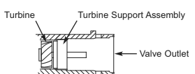
- Make sure the turbine assembly spins freely in the “out” port of the valve (See Figure 10).
- If not already done, put a light coating of silicone grease on the single bypass valve o-rings.
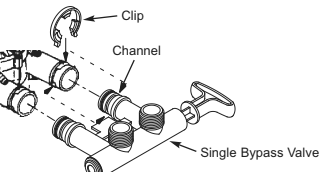
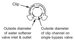
- Push the single bypass valve into the softener valve as far as it will go. Snap the two large holding clips into place, from the top down as shown in Figures 12 & 13.
IMPORTANT: Be sure the clips snap firmly into place so the single bypass valve will not pull out.
Step 4. Complete Inlet and Outlet Plumbing
Measure, cut, and loosely assemble pipe and fittings from the main water pipe to the inlet and outlet ports of the water softener valve. Be sure to keep fittings fully together, and pipes squared and straight.
Be sure hard water supply pipe goes to the water softener valve inlet side.
NOTE: Inlet and outlet are marked on the water softener valve. Trace the water flow direction to be sure hard water is to inlet.
IMPORTANT: Be sure to fit, align and support all plumbing to prevent putting stress on the water softener valve inlet and outlet. Undue stress from misaligned or unsupported plumbing may cause damage to the valve.
Complete the inlet and outlet plumbing for the type of pipes you will be using.
Correct Assembly
NOTE: Be sure all 3 tabs of the clip go through the matching holes on the water softener valve inlet or outlet, and fully into the channel on the single bypass valve. Make sure that the tabs are fully seated.
Step 5. Cold Water Pipe Grounding
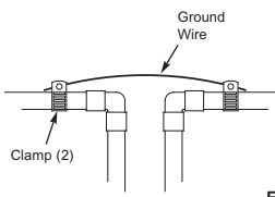
CAUTION: The house cold water pipe (metal only) is often used as a ground for the house electrical system, The 3-valve bypass type of installation, shown in Figure 8, will maintain ground continuity. If you use a plastic bypass valve at the unit, continuity is broken. To restore the ground, do the following:
- Install a #4 copper wire across the removed section of main water pipe, securely clamping it at both ends (See Figure 14) – parts not included.
NOTE: Check local plumbing and electrical codes for proper installation of the ground wire. The installation must conform to them. In
Massachusetts, plumbing codes of Massachusetts shall be conformed to. Consult with your licensed plumber.
Step 6. Install Valve Drain Hose
NOTE: See valve drain options on pages 7 & 8.
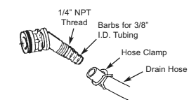
- Measure, cut to needed length and connect the 3/8″ drain line (provided) to the water softener valve drain fitting. Use a hose clamp to hold the hose in place.
IMPORTANT: If codes require a rigid drain line see “Valve Drain requirements” section.
- Run the drain hose (or a rigid line) to the floor drain. Secure drain hose. This will prevent “whipping” during regenerations. Be sure to provide a 1-1/2” minimum air gap to prevent possible sewer water backup. See “Air Gap Requirements” section.
NOTE: In addition to a floor drain, you can use a laundry tub or standpipe as a good drain point for this hose.. Avoid long drain hose runs, or elevating the hose more than 8’ above the floor.
Step 7. Install Salt Storage Tank Over flow Hose
- Measure, cut to needed length and connect the 3/8″ drain line (provided) to the salt storage tank overflow elbow and secure in place with a hose clamp.
- Run the hose to the floor drain, or other suitable drain point no higher than the drain fitting on the salt storage tank (This is a gravity drain). If the tank overfills with water, the excess water flows to the drain point. Cut the drain line to the desired length and route it neatly out of the way.
IMPORTANT: For proper operation of the water softener, do not connect the water softener valve drain hose from Step 6 to the salt
storage tank overflow hose.
Step 8. Pressure Testing for Leaks
To prevent air pressure in the water softener and plumbing system, do the following steps exactly in order:
- Fully open two or more softened cold water faucets nearby the water softener, located downstream from the water softener.
- Place the single bypass valve or 3 valve bypass in “bypass” position. See Figures 7 & 8.
- Fully open the main water supply valve. Run water until there is a steady flow from the opened faucets, with no air bubbles.
- Place bypass valve(s) in “service” or soft water position exactly as follows:
- Single bypass valve: Slowly move the valve stem toward “service,” pausing several times to allow the water softener to fill with water.
- 3 valve bypass: Fully close the bypass valve and open the outlet valve. Slowly open the inlet valve, pausing several times to allow the water softener to fill with water.
- After about three minutes, open a hot water faucet until there is a steady flow and there are no air bubbles, then close this faucet.
- Close all cold water faucets and check for leaks at the plumbing connections that you made.
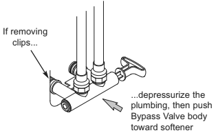
- Check for leaks around clips at softener’s inlet and outlet. If a leak occurs at a clip, depressurize the plumbing (turn off the water supply and open faucets) before removing clip. When removing clips at the softener’s inlet or outlet, push the single bypass valve body toward the softener (See Figure 15). Improper removal may damage clips. Do not reinstall damaged clips.
Step 9. Add Water and Salt to the Salt Storage Tank
- Using a container, add about three gallons of clean water into the salt storage tank.
- Add Morton® System Saver® II Pellets to the storage tank.
Step 10. Plug in the Power Supply
During installation, the water softener wiring may be moved or jostled from place. Check to be sure all leadwire connectors are secure on the back of the electronic board and be sure all wiring is away from the valve gear and motor area, which rotates during regenerations.
- Plug the water softener’s power supply into an electrical outlet that is not controlled by a switch and is approved by local codes.
Step 11. Program the Controller
- Install the softener’s top cover and salt lid.
- Complete the programming steps on: Models M20, M27, M30 & MC30 or Model M34.
Step 12. Sanitizing the Softener
Care is taken at the factory to keep your unit clean and sanitary. Materials used to make the unit will not infect or contaminate your water supply, and will not cause bacteria to form or grow. However, during shipping, storage, installation and operation, bacteria could get
into the unit. For this reason, sanitizing as follows is suggested* when installing.
- Open salt lid, remove the brinewell cover and pour about 3 oz. (6 tablespoons) of household bleach into the softener brinewell. Replace the brinewell cover.
- Make sure the bypass valve(s) is in the “service” (open) position.
- Start a recharge: Press the RECHARGE button and hold for 3 seconds, until “RECHARGE NOW” begins to flash in the display. This recharge draws the sanitizing bleach into and through the water softener. Any air remaining in the unit is purged to the drain.
- After the recharge has completed, fully open a cold water faucet, downstream from the softener, and allow 50 gallons of water to pass through the system. This should take at least 20 minutes. Close the faucet.
*Recommended by the Water Quality Association. On some water supplies, the unit may need periodic disinfecting.
Step 13. Restart the Water Heater
Turn on the electricity or fuel supply to the water heater and relight the pilot, if applicable.
NOTE: The water heater is filled with hard water and, as hot water is used, it refills with conditioned water. In a few days, the hot water will be fully conditioned. To have fully conditioned hot water immediately, wait until the initial recharge (Step 12) is over. Then, drain the water heater (following instructions for water heater) until water runs cold.
Programming the Water Softener (Models M20, M27, M30 & MC30)
Clean Reminder
The screen in Figure 18 appears, with “CLEAn” flashing in the display, when four months have elapsed on the system’s timer since start up or the last reset.

This is a reminder to use Morton® MWSC Water Softener Cleanser three times a year. To reset the timer, press any button on the control panel and “CLEAN” will disappear.
Program the Softener
When the power supply is plugged into the electrical outlet, the model code and a software version number (example: J3.9), are briefly shown in the display. Then the words “PRESENT TIME” appear and “12:00 PM” begins to flash.
NOTE: If “- – – -” shows in the display, press the UP or DOWN button until the model code shows in the display. Then,
press the SELECT button to set, and change to the flashing “PRESENT TIME” display.
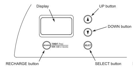
Step 1. Set Time of Day
If the words “PRESENT TIME” do not show in the display, press the SELECT button until they do.
- Press the UP or DOWN buttons to set the present time. Up moves the display ahead; down sets the time back. Be sure AM or PM is correct.

NOTE: Press buttons and quickly release to slowly advance the display. Hold the buttons down for fast advance.
Step 2. Set Water Hardness Number
- Press the SELECT button once again to display a flashing “25” and the word “HARDNESS”.
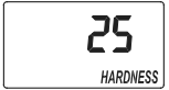
- Press the UP or DOWN buttons to set your water’s hardness number.
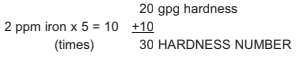
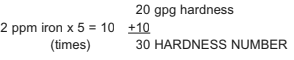
NOTE: If your water supply contains iron, compensate for it by adding to the water hardness number. For example, assume your water is
20 gpg hard and contains 2 ppm iron. Add 5 to the hardness number for each 1 ppm of iron. In this example, you would use 30 for your hardness number.
Step 3. Set Recharge (Regeneration) Time
Your demand water softener will automatically regenerate when it needs to, based on water usage. The time of day that the automatic recharge cycle begins may be changed as follows:
- Press the SELECT button once again to display a flashing “2:00AM” and the words “RECHARGE TIME”. This is a good time for the recharge to start in most households, because water is not in use.

- If you want to change the recharge start time, press the UP or DOWN buttons until the desired time shows. Be sure AM or PM is correct.
- Press the SELECT button once more to complete the initial programming. The current time of day will show in the display.
Step 4. Salt Efficiency
When this feature is ON, the water softener will operate at salt efficiencies of 4000 grains of hardness per pound of salt or higher (May recharge more often using smaller salt dosage but more regeneration water). The softener is shipped with this feature set OFF.
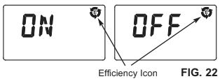
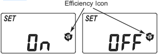
- Press and hold the SELECT button until one of the screens in Figure 21 is displayed. Once in this display, press the SELECT button once and one of the two displays in Figure 22 is shown.

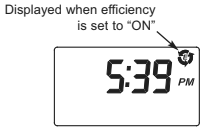
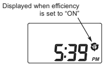
- Press the p UP or q DOWN buttons to set ON or OFF. When set to ON, the efficiency icon will be displayed in the upper right hand corner of the normal run display.
- Press the SELECT button three times, to return to the normal run display (See Figure 23).
California Efficiency Requirement
Your Morton® Water Softener has a “High Efficiency” feature with an ON or OFF setting. This softener setting is shipped in the OFF position, which utilizes the maximum rated capacity while most often achieving maximum salt efficiencies. When installing this unit in the State of California, you MUST turn this setting to the ON position, which may initiate more frequent recharges. However it will operate at 4000
grains per pound of salt or higher.
If you wish to turn the Salt Efficiency feature ON ( icon will show in the display).
Customizing Features / Options (Models M20, M27, M30 & MC30)
Recharge Now
At times of greater than normal water use, such as when you have guests, you could run out of conditioned water before the next scheduled recharge. If this happens, you may want to initiate an immediate regeneration, as follows:
- Press and hold the RECHARGE button until the words “RECHARGE NOW” flash in the display.

The softener enters the fill cycle of regeneration right away. “RECHARGE NOW” will flash during the regeneration. When completed (in about 2 hours), full water conditioning capacity is restored.
NOTE: Avoid using hot water while the softener is regenerating, because the water heater will refill with bypass hard water.
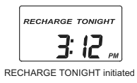
Recharge Tonight
If you do not want to start an immediate recharge, but would like an extra recharge at the next preset recharge time, do the following to schedule a recharge:
- Press and release (do not hold) the RECHARGE button.
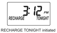
The words “RECHARGE TONIGHT” flash in the display, and the softener will recharge at the next preset recharge time (If you decide to cancel the regeneration before it begins, press and release the RECHARGE button once more, and “RECHARGE TONIGHT” will disappear from the display). During regeneration, the word “RECHARGE NOW” will flash in the screen. When completed, full water conditioning capacity is restored.
Adjustable Backwash
If your incoming water supply has higher sediments or clear water iron, a longer Backwash and/or Fast Rinse time may help in keeping the unit cleaner.
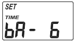
To change the length of the Backwash:
- Press and hold the SELECT button until the screen in Figure 26 is displayed.
- Press the SELECT button twice, so that “bA TIME” appears in the display (See Figure 27).
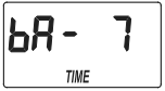
- Press the UP or DOWN buttons to set the length of Backwash in minutes.
- When the desired Backwash time appears in the display, press the SELECT button twice to return to the normal run (time of day) screen.
Adjustable Fast Rinse
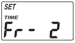
To change the length of the Fast Rinse:
- Press and hold the SELECT button until the screen in Figure 26 is displayed.
- Press the SELECT button three times, so that “Fr TIME” appears in the display (See Figure 28).
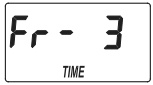
- Press the UP or DOWN buttons to set the length of Fast Rinse in minutes.
- When the desired Fast Rinse time appears in the display, press the SELECT button once to return to the normal run (time of day) screen.
Programming the Water Softener (Model M34)
Low Salt Light / Clean Reminder
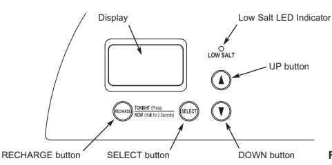
When the water softener is connected to electrical power, the light on the control panel will operate as follows:
- Light flashing, with the time of day shown in the display – The salt monitor system indicates a low salt level and needs to be set. See “Set Salt Level”
- Light flashing, with “CLEAn” flashing in the display (See Fig. 30) – Four months have elapsed on the system’s timer since start up or the last reset.

This is a reminder to use Morton® MWSC Water Softener Cleanser three times a year. To reset the timer, press any button on the control panel and “CLEAn” will disappear. The light will stop flashing, unless the system is also low on salt (see above).
Program the Softener
When the power supply is plugged into the electrical outlet, the model code and a software version number (example: J3.9), are briefly shown in the display. Then the words “PRESENT TIME” appear and “12:00 PM” begins to flash.
NOTE: If “- – – -” shows in the display, press the UP or DOWN button until the model code shows in the display. Then, press the SELECT button to set, and change to the flashing “SET TIME” display.
Step 1. Set Time of Day
If the words “SET TIME” do not show in the display, press the SELECT button until they do.
- Press the p UP or q DOWN buttons to set the present time. Up moves the display ahead; down sets the time back. Be sure AM or PM is correct.

NOTE: Press buttons and quickly release to slowly advance the display. Hold the buttons down for fast advance.
Step 2. Set Water Hardness Number
- Press the SELECT button once again to display a flashing “25” and the word “HARDNESS”.
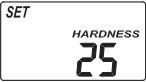
- Press the UP or DOWN buttons to set your water’s hardness number.
NOTE: If your water supply contains iron, compensate for it by adding to the water hardness number. For example, assume your water is
20 gpg hard and contains 2 ppm iron. Add 5 to the hardness number for each 1 ppm of iron. In this example, you would use 30 for
your hardness number.
Step 3. Set Recharge (Regeneration) Time
Your demand water softener will automatically regenerate when it needs to, based on water usage. The time of day that the automatic recharge cycle begins may be changed as follows:
- Press the SELECT button once again to display a flashing “2:00AM” and the words “SET RECHARGE TIME”. This is a good time for the recharge to start in most households, because water is not in use.

- If you want to change the recharge start time, press the p UP or q DOWN buttons until the desired time shows. Be sure AM or PM is correct.
Step 4. Set Salt Level
The water softener has a low salt indicator light to remind you to refill the storage tank with salt.
NOTE: You must set salt level each time salt is added to the water softener.
To set this monitor system:
- Lift the salt lid and level the salt in the storage tank.
- The salt level scale, on the brinewell inside the tank, has numbers from 0 to 8 (See Fig. 34). Observe the highest number the leveled salt is at, or closest to.
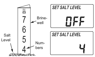
- Press the SELECT button to display the words “SET SALT LEVEL”.
- Press the UP or DOWN buttons until the number on the screen corresponds to the salt level. At level 2 or below, the“Low Salt” indicator light will flash. If you wish to turn this feature off, press the q DOWN button past 0, and the word “OFF” flashes in the display.
- Press the SELECT button once more to complete the initial programming. The current time of day will show in the display.
Step 5. Set Salt Efficiency
When this feature is ON, the water softener will operate at salt efficiencies of 4000 grains of hardness per pound of salt or higher (May recharge more often using smaller salt dosage but more regeneration water). The softener is shipped with this feature set OFF.
- Press and hold the SELECT button until one of the screens in Figure 35 is displayed. Once in this display, press the SELECT button once and one of the two displays in Figure 36 is shown.

- Press the UP or DOWN buttons to set ON or OFF. When set to ON, the efficiency icon will be displayed on the right hand side of the normal run display.
- Press the SELECT button three times, to return to the normal run display (See Figure 37).
California Efficiency Requirement
Your Morton® Water Softener has a “High Efficiency” feature with an ON or OFF setting. This softener setting is shipped in the OFF position, which utilizes the maximum rated capacity while most often achieving maximum salt efficiencies. When installing this unit in the State of California, you MUST turn this setting to the ON position, which may initiate more frequent recharges. However it will operate at 4000
grains per pound of salt or higher. If you wish to turn the Salt Efficiency feature ON ( icon will show in the display).
Recharge Now
At times of greater than normal water use, such as when you have guests, you could run out of conditioned water before the next scheduled recharge. If this happens, you may want to initiate an immediate regeneration, as follows:
- Press and hold the RECHARGE button until the words “RECHARGE NOW” flash in the display.

During the recharge cycle, the screen will flash “RECHARGE NOW”. When the recharge cycle is complete, full softened water capacity will be
restored.
NOTE: Avoid using hot water while the softener is regenerating, because the water heater will refill with bypass hard water.
Recharge Tonight
If you do not want to start an immediate recharge, but would like to schedule an extra recharge at the next preset recharge time, do the following:
- Press and release (do not hold) the RECHARGE button.
The words “RECHARGE TONIGHT” flash in the display, and the softener will recharge at the next recharge time. The words “RECHARGE NOW” will flash during the regeneration. When completed, full water conditioning capacity is restored.
Adjustable Backwash
If your incoming water supply has higher sediments or clear water iron, a longer Backwash and/or Fast Rinse time may help in keeping the unit cleaner.
To change the length of the Backwash:
- Press and hold the SELECT button until the screen in Figure 40 is displayed.
- Press the SELECT button twice, so that “SET TIME bA” appears in the display (See Figure 41).
- Press the p UP or q DOWN buttons to set the length of Backwash in minutes.*
- When the desired Backwash time appears in the display, press the SELECT button twice to return to the normal run (time of day) screen.
Adjustable Fast Rinse
To change the length of the Fast Rinse:
- Press and hold the SELECT button until the screen in Figure 40 is displayed.
- Press the SELECT button three times, so that “SET TIME Fr” appears in the display (See Figure 42).
- Press the p UP or q DOWN buttons to set the length of Fast Rinse in minutes.*
- When the desired Fast Rinse time appears in the display, press the SELECT button once to return to the normal run (time of day) screen.
- Setting backwash and/or fast rinse times too low may result in salty tasting water after regeneration.
Customizing Features / Options (All Models)
Power Outage Memory
If electrical power to the softener is interrupted, the time display is blank, but the electronic controller keeps correct time for several hours. When power is restored, you must reset the present time only if the display is flashing. All other settings are maintained and never require resetting unless a change is desired. If the time is flashing after a long power outage, the softener continues to work as it should to provide you with soft water. However, regenerations may occur at the wrong time of day until you reset the clock to the correct time of day.
NOTE: If the water softener was regenerating when power was lost, it will now finish the cycle.
Routine Maintenance
Refilling with Salt
Lift the salt lid and check the salt storage level frequently. If the water softener uses all the Morton® Clean and Protect TM or Clean and Protect TM Plus Rust Defense TM Pellets before you refill it, you will experience hard water. Until you have established a refilling routine, check the salt every two or three weeks. Always add if less than 1/4 full. Be sure the brinewell
cover is on.
NOTE: In humid areas, it is best to keep the salt storage level lower, and to refill more often to avoid salt “bridging”.
Recommended Salt: We recommend using Morton® Clean and Protect TM or Clean and Protect TM Plus Rust Defense TM Pellets in the familiar yellow bag. For soft water, nothing works harder. Guaranteed®.
Salt Not Recommended: Rock salt, high in impurities, block, granulated, table, ice melting, ice cream making salts, etc., are not recommended.
Salt with Iron Removing Additives: Some salts have an additive to help a water conditioner handle iron in a water supply. For this we recommend Morton® Rust Remover Super Pellets® in the green bag.
Breaking a Salt Bridge
Sometimes, a hard crust or salt “bridge” forms in the brine tank. It is usually caused by high humidity or the wrong kind of salt. When the salt “bridges,” an empty space forms between the water and the salt. Then, salt will not dissolve in the water to make brine. Without brine, the resin bed is not recharged and hard water will result.
If the storage tank is full of salt, it is difficult to tell if you have a salt bridge. A bridge may be underneath loose salt. Take a broom handle, or like tool, and hold it next to the water softener. Measure the distance from the floor to the rim of the water softener. Then, carefully push the broom handle straight down into the salt. If a hard object is felt before the pencil mark is even with the top, it is most likely a salt bridge.
Carefully push into the bridge in several places to break it. Do not use any sharp or pointed objects as you may puncture the brine tank. Do not try to break the salt bridge by pounding on the outside of the salt tank. You may damage the tank.
Cleaning the Nozzle & Venturi
A clean nozzle & venturi (See Figure 44) is a necessity for the water softener to work properly. This small component creates the suction to move brine from the brine tank, into the resin tank. If it should become plugged with sand, silt, dirt, etc., the water softener will not work, and hard water will result.
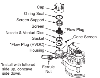
IMPORTANT: Be sure small hole in the gasket is centered directly over the small hole in the nozzle & venturi housing. Be sure the numbers are facing up.
To get access to the nozzle & venturi, remove the water softener’s top cover. Put the bypass valve(s) into the bypass position. Be sure the water softener is in soft water (service) cycle (no water pressure at nozzle & venturi). Then, holding the nozzle & venturi housing with one hand, un screw the cap. Do not lose the o-ring seal. Lift out the screen support and screen. Then, remove the nozzle & venturi disc, gasket and flow plug(s). Wash the parts in warm, soapy water and rinse in fresh water. Be sure to clean both the top and bottom of the nozzle & venturi disc. If needed, use a small brush to remove iron or dirt. Do not scratch, misshape, etc., surfaces of the nozzle & venturi.
Carefully replace all parts in the correct order. Lubricate the o-ring seal with silicone grease and locate in place. Install and tighten the cap by hand, while supporting the housing. Overtightening may break the cap or housing. Put the bypass valve(s) into service (soft water) position.
Recharge the softener to reduce water level in the tank. This will also assure that the softener is completely recharged and ready to provide softened water again. Check the water level in the tank by looking down the brinewell. If the water level does not drop after a recharge, the problem has not been resolved. Call 1-888-64 WATER or visit www.mortonwatersofteners.com.
Protect the Water Softener from Freezing
If the softener is installed where it could freeze (summer cabin, lake home, etc.), you must drain all water from it to stop possible freeze damage. To drain the softener:
- Close the shut-off valve on the house main water pipe, near the water meter or pressure tank.
- Open a faucet in the soft water pipes to vent pressure in the softener.
- Move the stem in the single bypass valve to bypass. Close the inlet and outlet valve in a 3 valve bypass system, and open the bypass valve. If you want water in the house pipes again, reopen the shut-off valve on the main water pipe.
- Unplug the power supply at the wall outlet. Remove the softener’s top cover, together with the salt lid. Take off both drain hoses if they will interfere with moving the softener into position over the drain.
- Push the bypass valve body toward the softener (as shown in Figure 15) and carefully remove the large holding clips at the softener inlet and outlet. Separate the softener from the plastic installation adaptors, or from the bypass valve.
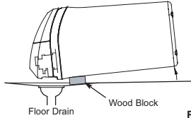
- Lay a piece of 2 inch thick board near the floor drain (See Figure 45).
- Move the softener close to the drain. Slowly and gently, tip it over until the rim rests on the wood block with the inlet and outlet over the drain. Do not allow the softener’s weight to rest on the inlet and outlet fittings or they may break.
- Tip the bottom of the softener up a few inches and hold until all water has drained. Leave the softener laying like this until you are ready to use it. Plug the inlet and outlet with clean rags to keep dirt, bugs, etc. out.
Troubleshooting
Automatic Electronic Diagnostics
This water softener has a self-diagnostic function for the electrical system (except input power and/or water meter). The water softener monitors electronic components and circuits for correct operation. If a malfunction occurs, an error code appears in the display.

While an error code appears in the display, all buttons are inoperable except the SELECT button. SELECT remains operational so the service person can perform the Manual Advance Diagnostics, see below, to further isolate the problem.
Procedure for removing error code from display:
- Unplug power supply from electrical outlet.
- Correct problem.
- Plug power supply back in.
- Wait 8 minutes. The error code will return if the problem was not corrected.
Manual Advance Diagnostics
Use the following procedures to advance the water softener through the regeneration cycles to check operation.
Remove the top cover to expose the valve and observe cam and switch operation during valve rotation.
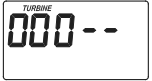
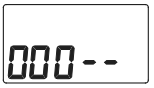
- Press and hold SELECT for 3 seconds until “000” shows in the display, then release.
- The 3 digits indicate water meter operation as follows:
000 (steady) = Soft water not in use, and no flow through the meter.
Open a nearby soft water faucet.
000 to 199 (continual) = Repeats for each gallon of water passing through the meter.
- The letter “P” and a dash (or dashes) indicate POSITION switch operation (See Figure 47). If the letter appears, the switch is closed. If the dash shows, the switch is open.
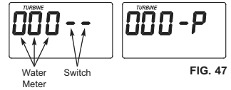
- Use the RECHARGE button to manually advance the valve into each cycle and check correct switch operation.
NOTE: Be sure water is in contact with the salt, and not separated by a salt bridge (See “Breaking A Salt Bridge” section).
- While in this diagnostic screen, the following information is available and may be beneficial for various reasons. This information is retained by the computer from the first time electrical power is applied to the electronic controller.
a. Press the UP button to display the number of days this electronic control has had electrical power applied.
b. Press the DOWN button to display the number of regenerations initiated by this electronic control since the code number was entered.
- Press and hold the SELECT button until the model code shows in the display. This code identifies the softener model. If an incorrect model code is displayed, the softener will operate on incorrect configuration data.

- To change the code number, press the UP or DOWN button until the correct code shows.
- To return to the present time display, press the SELECT button.
Resetting to Factory Defaults
- Press the SELECT button and hold it until the display changes twice to show “CODE” and the flashing model code.
- Press the p UP button (a few times, if necessary) to display a flashing “SoS”.
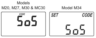
- Press the SELECT button, and the electronic controller will restart.
- Set the present time, hardness, etc., as described on pages 13 & 14 (for Models M20, M27, M30 & MC30) or pages 16-18 (for Model M34).
Manual Advance Regeneration Check
This check verifies proper operation of the valve motor, brine tank fill, brine draw, regeneration flow rates, and other controller functions. Always make the initial checks, and the manual initiated diagnostics.
NOTE: The electronic control display must show a steady time (not flashing). If an error code shows, first press the SELECT button to enter
the diagnostic display.
- Press the RECHARGE button and hold in for 3 seconds. RECHARGE begins to flash as the softener’s valve advances from the service to fill position. Remove the brinewell cover and, using a flashlight, observe fill water entering the tank. If water does not enter the tank, look for an obstructed nozzle, venturi, fill flow plug, brine tubing, or brine valve riser pipe.
- After observing fill, press the RECHARGE button to move the softener’s valve into the brine position. A slow flow of water to the drain will begin. Verify brine draw from the brine tank by shining a flashlight into the brinewell and observing a noticeable drop in the liquid level. This may take 15 to 20 minutes.
NOTE: Be sure water is in contact with the salt, and not separated by a salt bridge (See “Breaking A Salt Bridge” section).
If the water softener does not draw brine, check for (most likely to least likely):
- Dirty or plugged nozzle and venturi, see “Cleaning the Nozzle and Venturi” section.
- Nozzle and venturi not seated on the gasket, or gasket deformed.
- Valve seals leaking.
- Restriction in valve drain, causing a back-pressure (bends, kinks, elevated too high, etc.). See “Install Valve Drain Hose” section.
- Obstruction in brine valve or brine tubing.
NOTE: If water system pressure is low, an elevated drain hose may cause back pressure, stopping brine draw.
- Press the RECHARGE button to move the softener’s valve into the backwash position. Look for a fast flow of water from the drain hose. Check that the drain can adequately handle the flow and volume. An obstructed flow indicates a plugged top distributor, backwash flow plug, or drain hose.
- Press the RECHARGE button to move the softener’s valve into the fast rinse position. Again look for a fast drain flow. Allow the softener to rinse for a few minutes to flush out any brine that may remain in the resin tank from the brining cycle test.
- To return the softener’s valve to the service position, press the RECHARGE button.
Need help troubleshooting? Call Toll Free 1-888-64 WATER (1-888-649-2837) or visit www.mortonwatersofteners.com When you call, please be prepared to provide the model and serial number, found on the rating decal, located on the rim below the salt lid hinges.
Softener Exploded View
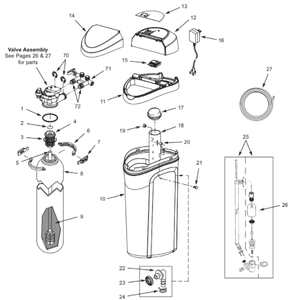
Softener Parts List
| Key No. | Part No. | Description |
| – | 7112963 | Distributor O-Ring Kit (includes Key Nos. 1-3) |
| 1 | 🡩 | O-Ring, 2-7/8” x 3-1/4” |
| 2 | 🡩 | O-Ring, 13/16” x 1-1/16” |
| 3 | 🡩 | O-Ring, 2-3/4” x 3” |
| 4 | 7077870 | Top Distributor |
| 5 | 7105047 | Repl. Bottom Distributor |
| – | 7331177 | Tank Neck Clamp Kit (includes Key Nos. 6 & 7) |
| 6 | 🡩 | Clamp Section (2 req.) |
| 7 | 🡩 | Retainer Clip (2 req.) |
| 8 | 7114787 | Repl. Resin Tank, 8” x 35”, Models M20 & M27 |
| 7264922 | Repl. Resin Tank, 9” x 35”, Models M30, MC30 & M34 | |
| 9 | 0502272 | Resin, 1 cu. ft. |
| 10 | 7331143 | Repl. Brine Tank |
| 11 | 7330977 | Rim |
| 12 | 7330985 | Top Cover (order decal below) |
| 13 | 7331371 | Faceplate Decal, Models M20, M27, M30 & MC30 |
| 7331630 | Faceplate Decal, Model M34 | |
| 14 | 7330993 | Salt Lid (order decal below) |
| ⬛ | 7331339 | Instruction Decal, Models M20, M27, M30 & MC30 |
| 7331614 | Instruction Decal, Model M34 |
| Key No. | Part No. | Description |
| 15 | 7331818 | Repl. Electronic Control Board (PWA), Models M20, M27, M30 & MC30 |
| 7331834 | Repl. Electronic Control Board (PWA), Model M34 | |
| 16 | 7351054 | Power Supply, 24V DC |
| 17 | 7155115 | Cover, Brinewell |
| 18 | 7109871 | Brinewell, Models M20, M27, M30 & MC30 |
| 7214375 | Brinewell Assembly (including salt level decal), Model M34 | |
| – | 7332204 | Brinewell Mounting Hardware Kit (includes Key Nos. 19-21) |
| 19 | 🡩 | Wing Nut, 1/4-20 |
| 20 | 🡩 | Spacer, 3/4” long |
| 21 | 🡩 | Screw, 1/4-20 x 1-1/2” |
| – | 7331258 | Overflow Hose Adaptor Kit (includes Key Nos. 22-24) |
| 22 | 🡩 | Adaptor Elbow |
| 23 | 🡩 | Grommet |
| 24 | 🡩 | Hose Clamp |
| 25 | 7310202 | Brine Valve Assembly |
| 26 | 7327568 | Float, Stem & Guide Assembly |
| 27 | 7139999 | Drain Hose |
| ⬛ | 7361724 | Owner’s Manual |
⬛ Not illustrated.
Questions? Call Toll Free 1-888-64 WATER (1-888-649-2837) or visit www.mortonwatersofteners.com When you call, please be prepared to provide the model and serial number, found on the rating decal, located on the rim below the salt lid hinges.
Valve Exploded View
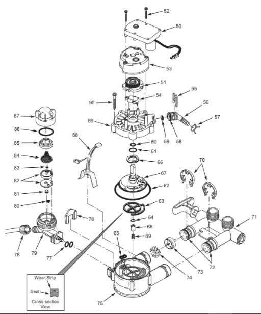
Valve Parts List
| Key No. | Part No. | Description |
| – | 7373810 | Motor, Cam & Gear Kit, 3/4” (includes Key Nos. 50-52) |
| 50 | 🡩 | Motor |
| 51 | 🡩 | Cam & Gear |
| 52 | 7338111 | Screw, #6-19 x 1-3/8” (2 req.) |
| 53 | 7337474 | Motor Mount |
| 54 | 7030713 | Switch |
| – | 7331185 | Drain Hose Adaptor Kit (includes Key Nos. 55-59) |
| 55 | 🡩 | Clip, Drain |
| 56 | 🡩 | Drain Hose Adaptor |
| 57 | 🡩 | Hose Clamp |
| 58 | 🡩 | O-Ring, 5/8” x 13/16” |
| 59 | 🡩 | Flow Plug, 2.0 gpm |
| – | 7129716 | Seal Kit (includes Key Nos. 60-65) |
| 60 | 🡩 | O-Ring, 7/16” x 5/8” |
| 61 | 🡩 | O-Ring, 3/4” x 15/16” |
| 62 | 🡩 | O-Ring, 3-3/8” x 3-5/8” |
| 63 | 🡩 | Rotor Seal |
| 64 | 🡩 | O-Ring, 3/8” x 9/16” |
| 65 | 🡩 | Seal, Nozzle & Venturi |
| 66 | 7082087 | Wave Washer |
| 67 | 7199232 | Rotor & Disc |
| – | 7342665 | Drain Plug Kit, 3/4” (includes Key Nos. 64, 68 & 69) |
| 68 | 🡩 | Plug, Drain Seal |
| 69 | 🡩 | Spring |
| Key No. | Part No. | Description |
| 70 | 7337563 | Clip, 3/4”, pack of 4 |
| 71 | 7370286 | Bypass Valve Assembly, 3/4”, in – cluding 2 O-Rings (See Key No. 72) |
| 72 | 7337571 | O-Ring, 15/16” x 1-3/16”, pack of 4 |
| – | 7113040 | Turbine & Support Assembly, including 2 O-Rings (See Key No. 72) & 1 ea. of Key Nos. 73 & 74 |
| 73 | 🡩 | Turbine Support & Shaft |
| 74 | 🡩 | Turbine |
| 75 | 7082053 | Valve Body |
| 76 | 7081201 | Retainer, Nozzle & Venturi |
| 77 | 7342649 | O-Ring, 1/4” x 3/8”, pack of 2 |
| 78 | 1202600 | Nut – Ferrule |
| – | 7238450 | Nozzle & Venturi Assembly (includes Key Nos. 76, 77 & 79-87) |
| 79 | 7081104 | Housing, Nozzle & Venturi |
| 80 | 7095030 | Cone Screen |
| 81 | 1148800 | Flow Plug, .3 gpm |
| 82 | 7187772 | Nozzle & Venturi Gasket Kit |
| 7204362 | Gasket Only | |
| 83 | 0521829 | Flow Plug, .1 gpm |
| 84 | 7146043 | Screen |
| 85 | 7167659 | Screen Support |
| 86 | 7170262 | O-Ring, 1-1/8” x 1-3/8” |
| 87 | 7199729 | Cap |
| 88 | 7309803 | Wire Harness, Sensor |
| 89 | 7337466 | Valve Cover |
| 90 | 7342657 | Screw, #10-14 x 5 cm, pack of 5 |
EXTEND YOUR WARRANTY:
Use Morton® MWSC Water Softener Cleanser
The factory warranty for your water softener is shown below. The one year warranty period, on all parts other than the salt storage tank and fiberglass mineral tank, can be extended to five (5) years from the date of purchase if you use Morton® MWSC Water Softener Cleanser on your system. Use one bottle of Morton® MWSC Water Softener Cleanser, as directed, every four months from the date of purchase of the water softener. Retain proof of purchase of Morton® MWSC Water Softener Cleanser to validate any warranty claim after the first year. Use of any water softener additive other than Morton® MWSC will invalidate any extended warranty coverage.
READ ALSO: Morton Water Softeners User’s Manual (Model MCWF)
WATER SOFTENER LIMITED WARRANTY
Seller warrants,to the original owner, that:
● For a period of ten (10) years from the date of purchase, the salt storage tank and fiberglass mineral tank will not rust, corrode, leak, burst, or fail to perform to their specifications.
● For a period of one (1) year from the date of purchase, all other parts will be free of defects in material and workmanship.
If, during such respective period, a part proves to be defective, Seller will ship a replacement part, directly to your home, without charge.
If you have questions regarding a Morton water softener or MWSC, need assistance with installation or troubleshooting, wish to order a part or report a warranty issue, we are just a phone call away. Simply dial 1-888-64WATER (1-888-649-2837) for assistance, or visit www.mortonwatersofteners.com.
This water softener is manufactured for Morton Salt, Inc., P.O. Box 25290, Woodbury, MN 55125-0290
General Provisions
The warranty does not apply to any defect, malfunction or failure arising from, relating to or caused by: (i) operation at water pressures which exceed 125 psi or at water temperatures which exceed 120°F; (ii) repairs made by others than, or without the consent of, Seller or if the product has been subject to abuse, misuse, neglect, tampering, accident or damage by circumstances beyond Seller’s control; (iii) products damaged or abused in shipment without fault of Seller; (iv) non-residential installations; (v) defects or failures due to misapplication, abuse, improper installation or abnormal conditions of temperature, humidity, abrasives, dirt or corrosive matter; (vi) unusual force of nature such as, but not limited to, flood, hurricane, tornado or earthquake; and (vii) products which have been in any way tampered with, modified or altered. The foregoing warranties do not cover and Seller shall not be responsible for reimbursement for labor, transportation, removal, installation, or other expenses which may be incurred by Purchaser in connection with replacement or repair or returning the product to Seller.
THERE ARE NO WARRANTIES ON THE WATER SOFTENER BEYOND THOSE SPECIFICALLY DESCRIBED ABOVE. ALL IMPLIED WARRANTIES, INCLUDING, WITHOUT LIMITATION, ANY IMPLIED WARRANTY OF MERCHANTABILITY OR OF FITNESS FOR A PARTICULAR PURPOSE ARE HEREBY DISCLAIMED. SELLER’S SOLE LIABILITY FOR ANY PRODUCT IS LIMITED TO THE REPAIR OR REPLACEMENT OF SUCH PRODUCT, OR A REFUND OF THE PURCHASE PRICE ACTUALLY RECEIVED BY SELLER FOR SUCH PRODUCT, AT SELLER’S SOLE DISCRETION. SELLER WILL NOT BE LIABLE FOR ANY INDIRECT, INCIDENTAL, SPECIAL, CONSEQUENTIAL OR PUNITIVE DAMAGES OF ANY KIND, NATURE OR DESCRIPTION WHATSOEVER. NO MORTON DEALER, AGENT, REPRESENTATIVE, OR OTHER PERSON IS AUTHORIZED TO EXTEND, EXPAND OR MODIFY THE WARRANTIES EXPRESSLY DESCRIBED ABOVE.
Some states do not allow limitations on how long an implied warranty lasts or exclusions or limitations of incidental or consequential damage, so the limitations and exclusions in this warranty may not apply to you. This warranty gives you specific legal rights, and you may have other rights which vary from state to state. This warranty applies to consumer-owned installations only.
You can download the PDF version of the Morton Water Softeners User’s Manual here.