SPACE-MAKER MODELS:
NLS0500 NLS0501
NLS0750 NLS0751
NLS1000 NLS1001
NLSM0750 NLSM0751
NLSM1000 NLSM1001
TWO TANK MODELS:
NS0750 NS0751
NS1000 NS1001
NS1500 NS1501
NS2000 NS2001
NS2500 NS2501
NSM0750 NSM0751
NSM1000 NSM1001
NSM1500 NSM1501
NSM2000 NSM2001
NSM2500 NSM2501
Cuno Water Treatment A Division of CUNO Incorporated 12628 U.S. 33 North, Churubusco, IN 46723
Copyright 2005 by Cuno Water Treatment. All rights reserved. Not to be reprinted in any form without written permission.
READ ALSO: Pure Aqua Reverse Osmosis & Water Treatment Systems – PENTAIR FLECK 5600SXT DOWNFLOW SERVICE MANUAL
BEFORE INSTALLATION
Congratulations! We believe your purchase of this water softener will prove to be a very wise choice. When properly installed, your new softener will provide many years of trouble-free service. Before starting the installation we suggest you read this manual all the way through for an overview, and then follow the installation steps in the proper sequence. IMPROPER INSTALLATION could void the warranty.
INSPECTING AND HANDLING YOUR WATER SOFTENER:
Inspect the equipment for shipping damage. If damaged, notify the transportation company and request a damage inspection.
Handle the equipment with care. Damage can result if dropped or if the brine tank is set on sharp, uneven projections on the floor. When handling, do not turn the water softener unit upside down.
MAKE SURE YOUR WATER HAS BEEN THOROUGHLY TESTED:
An analysis of your water should be made prior to the selection of your water conditioning equipment. Your dealer will generally perform this service for you, and may send a sample to the factory for analysis and recommendations. Enter your analysis below for a permanent record.
NOTE: Hydrogen sulfide (H2S) must be tested for at the well site. For accuracy, the sample must be drawn with the pump RUNNING, and the test be completed within ONE minute after the sample is drawn.
NOTE: Softeners are designed to remove hardness but can handle reasonable amounts of soluble iron if consideration is given to content when selecting model and regeneration settings. To treat sulfur (hydrogen sulfide), bacterial iron, precipitated iron or very high levels of soluble iron requires special equipment in addition to a water softener. For best results, a Chem-FreeTM Iron Removal System is recommended for use on waters containing more than 2 ppm of iron.
ANALYSIS OF YOUR WATER
Hardness _______________ gpg
Iron (Fe) _______________ ppm
Manganese (Mn) _______________ ppm
pH _______________
Tannins (Humic Acid) _______________ ppm
Hydrogen sulfide (H2S) _______________ ppm
Other ________________
Other ________________
CHECK YOUR WATER PRESSURE AND PUMPING RATE:
Two water system conditions must be checked carefully to avoid unsatisfactory operation or equipment damage:
1) MINIMUM water pressure required at the filter tank inlet is 20 psi. IF PRESSURE IS OVER 100 PSI, A PRESSURE REDUCING VALVE MUST BE INSTALLED IN THE WATER SUPPLY LINE AHEAD OF THE WATER SOFTENER.
NOTE: If you have a municipal or a community water supply and daytime water pressure is 85 psi or more, nighttime pressure may exceed 100 psi. Call your local water department or plant operator to obtain pressure readings. If you have a private well, the gauge on the
pressure tank will indicate the high and low system pressure. Record your water pressure data below:
WATER PRESSURE
Low ________________ psi High ________________ psi
IMPORTANT: Damage to system can occur (including possible mineral tank structural failure resulting in a water leak) if system is subjected to a vacuum. The installer should take appropriate measures if there is the possibility a vacuum may occur. This would include the installation of an appropriate device in the supply line to the system, i.e., a vacuum breaker or backflow prevention device. Vacuum damage
voids the factory warranty.
2) The pumping rate of your well pump must be sufficient for satisfactory operation and BACKWASHING of the WATER SOFTENER. (see SPECIFICATIONS AND OPERATING DATA , Section5)
LOCATE WATER CONDITIONING EQUIPMENT CORRECTLY:
Select the location of your water softener with care. Various conditions which contribute to proper location are as follows:
1) Locate as close as possible to water supply source.
2) Locate as close as possible to a floor or laundry tub drain.
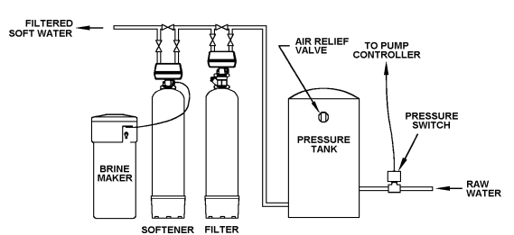
3) Locate in correct relationship to other water conditioning equipment (Figure 1).
4) Locate the softener in the supply line BEFORE the water heater. Temperatures above 100°F (38°C) will damage the softener and void the factory warranty.
5) Do NOT install the softener in a location where freezing temperatures occur. Freezing may cause permanent damage and will also void the factory warranty.
6) Allow sufficient space around the unit for easy servicing.
7) Provide a non-switched 110/120V, 60Hz power source for the control.
FACTS TO REMEMBER WHILE PLANNING YOUR INSTALLATION:
(1) All installation procedures MUST conform to local and state plumbing codes.
(2) If lawn sprinkling, a swimming pool, or geothermal heating/cooling or water for other devices/activities are to be treated by the water softener, a larger model MUST be selected to accommodate the higher flow rate and softening demand of these items. The pumping rate of the well pump must be sufficient to accomodate these items plus the backwashing requirements of the water softener. Consult your dealer for alternative instructions if the pumping rate is insufficient.
(3) Remember that the water softener INLET is attached to the pipe that supplies water (i.e., runs to the pump), and the OUTLET is the line that runs toward the water heater.
(4) Before commencing the installation it is advisable to study the existing piping system and to determine the size, number and type of fittings required.
NOTE: If the plumbing system is used as the ground leg of the electrical supply, continuity should be maintained by installing ground straps around any nonconductive plastic piping used in installation.
(5) It is also advisable to sweep the floor to eliminate objects that could pierce the brine tank.
(6) SODIUM INFORMATION: Water softeners using sodium chloride for regeneration add sodium to the water. Persons who are on sodium restricted diets should consider the added as part of their overall sodium intake.
INSTALLATION
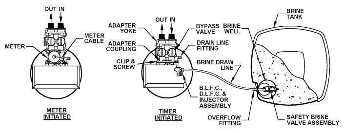
Step 1.If not factory pre-installed, attach BYPASS VALVE or YOKE ASSEMBLY using ADAPTER COUPLINGS, CLIPS and SCREWS to CONTROL VALVE (Figure 2). On meter initiated models, attach METER between BYPASS VALVE and CONTROL VALVE (Figure 2).
Step 2. On Series 2501 ONLY attach salt grid leg extensions (provided) to bottom of salt grid legs by snapping nipple on end of extension into hole in the bottom of the grid leg. NOTE: Extension legs should be installed whenever salt dosage on any model softener is 15 lbs. or more. Verify all packing materials have been removed from the brine tank. On all units, push salt grid down into brine tank until grid legs rest on bottom of brine tank.
Step 3. Shut off all water at main supply valve. On a private well system, turn off power to pump and drain pressure tank. Make certain pressure is relieved from complete system by opening nearest faucet to drain system. SHUT OFF FUEL SUPPLY TO WATER HEATER.
Step 4. Cut main supply line as required to fit plumbing to INLET and OUTLET of unit.
Step 5. Attach plumbing. DO NOT apply heat to any fitting connected to BYPASS or CONTROL VALVE as damage may result to internal parts or connecting adapters. MAKE CERTAIN WATER FLOW ENTERS THROUGH INLET AND DISCHARGES THROUGH OUTLET.
Step 6. Attach DRAIN LINE to DRAIN LINE FITTING. To prevent back pressure from reducing flow rate below minimum required for backwash, DRAIN LINE MUST be sized according to run length and relative height. Be careful not to bend flexible drain tubing sharply enough to cause “kinking” (if kinking occurs DRAIN LINE MUST BE REPLACED). Typical examples of proper DRAIN LINE diameters are:
- (1) 1/2 in. ID up to 15 ft. when discharge is lower than INLET.
- (2) 5/8 in. ID up to 15 ft. when discharge is slightly higher than INLET.
- (3) 3/4 in. ID when drain is 25 ft. away and/or drain is installed overhead.
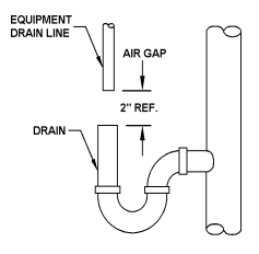
Step 7. Position DRAIN LINE over drain and secure firmly. To prevent backsiphoning of waste water, provide an air gap of at least 2 in. or 2 pipe diameters between end of drain hose and drain (Figure 3). DO NOT raise DRAIN LINE more than 10 ft. above floor.
Step 8. Connect one end of the 3/8 in. poly line to BRINE VALVE located on the right side of CONTROL VALVE. Connect other end to ELBOW inside of BRINE WELL. Brass insert sleeves and plastic ferrules must be used where necessary. (Figure 2 and CONTROL VALVE PARTS Drawing, Section 6).
Step 9. Install OVERFLOW LINE to brine tank OVERFLOW FITTING (Figure 2). Discharge of line must be lower than OVERFLOW FITTING. DO NOT INTERCONNECT OVERFLOW LINE WITH VALVE DRAIN LINE.
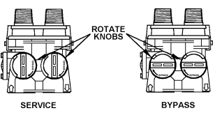
Step 10. Make certain BYPASS VALVE INLET and OUTLET KNOBS ARE IN “BYPASS” position. After all plumbing connections have been completed, open main water shut-off valve or restore power to well pump. Check for leaks and correct as necessary.
Step 11. Manually stage control to BACKWASH POSITION by turning “MANUAL REGENERATION KNOB”, clockwise to “BACKWASH” position, refer to HOW TO SET TIME CLOCK REGENERATION CONTROL (Section 3).
Step 12. Partially open INLET valve in plumbing or on BYPASS VALVE (Figure 4). This will allow the unit to fill slowly from the bottom up, eliminating air entrapment. Allow unit to fill slowly, failure to do so could result in loss of resin to the drain. Once a steady stream of water, no air, is flowing to drain, the INLET VALVE can be fully opened. The OUTLET valve can also be opened and the BY-PASS (if applicable) can be closed. Manually advance control to SERVICE POSITION. Plug into a non-switched 110/120V, 60Hz power source.
Step 13. On time clock initiated models, set REGENERATION FREQUENCY. Refer to REGENERATION FREQUENCY SCHEDULES (Section 3) to determine correct frequency, then refer to HOW TO SET TIME CLOCK REGENERATION CONTROL (Section 3) for instructions on setting frequency. For meter initiated models, refer to HOW TO SET METER REGENERATION CONTROL.
NOTE: Regeneration settings for both time clock and meter initiated models are factory preset for the most efficient salt use and minimum water consumption used for regeneration (as little as 50 gallons), and conform to the INDUSTRY SALT EFFICIENCY STANDARDS (required by some states). REGENERATION FREQUENCY SCHEDULES are designed for use with factory regeneration settings (listed in SPECIFICATIONS
AND OPERATING DATA, Section 5).
The control valve design permits adjustment of the salt dosage. This adjustment may be necessary when unusual operating conditions exist, such as high concentrations of iron or hardness and/or high flow rates or daily water consumption. This adjustment is easily performed by loosening the screw holding the white cam (on backside of timer) and adjusting the pointer to the desired pounds of salt.
NOTE: For salt dosages greater than 15 lbs, grid leg extensions must be attached to bottom of grid legs. For salt dosages less than 15 lbs. DO NOT use extension legs.
Step 14. Set TIME OF DAY (refer to appropriate HOW TO SET TIME CLOCK/METER REGENERATION CONTROL, Section 3). When shifting to daylight saving time (and back), you may wish to adjust TIME OF DAY accordingly.
NOTE: TIME OF REGENERATION is pre-set for 2:00 a.m. because at this time water consumption is generally minimal (a built-in hard water bypass does, however, permit water to be drawn during regeneration). Should your life style require regular use of water during the 2:00 to 3:00 a.m. regeneration period, or if other water treatment equipment is also set for 2:00 a.m. regeneration, the TIME OF REGENERATION will need changing. To change, adjust time of day on 24-HOUR GEAR ahead or behind actual time of day. For example, if 1:00 a.m. regeneration is desired and actual time of day is 10:00 a.m., advance 24- HOUR GEAR one hour to 11:00 a.m.; or, should 3:00 a.m. regeneration be desired, set gear back one hour to 9:00 a.m.
Step 15. Before loading salt, using a pail or garden hose, add approximately 3 gals. water to brine tank (6 gals. for units with extended grid legs). Then add initial salt fill to brine tank, and one cup full of unscented laundry bleach to brine well.
Step 16. Put softener through complete regeneration to sanitize the system before use (Refer to HOW TO SET TIME CLOCK (or METER) REGENERATION CONTROL for instructions on manual regeneration). RESTORE FUEL SUPPLY OR POWER TO WATER HEATER.
Installation is now complete, and your water softener is now ready for service!
SPECIAL SERVICE INSTRUCTIONS:
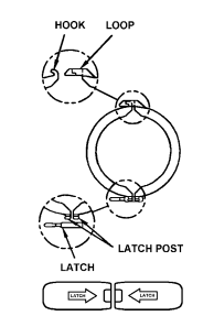
Under normal circumstances removal of valve should never be required. However, if it must be removed, it can be done by disassembling the quick release clamp, by removing latch. Pressure should be relieved before attempting any disassembly. Upon reassembly, all o-rings should be lubricated with silicone grease. Reassemble clamp as shown in Figure 5. MAKE SURE ARROWS ON LATCH SIDE OF CLAMP ARE ALIGNED.
REGENERATION INSTRUCTIONS
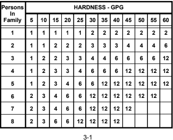
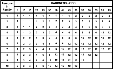
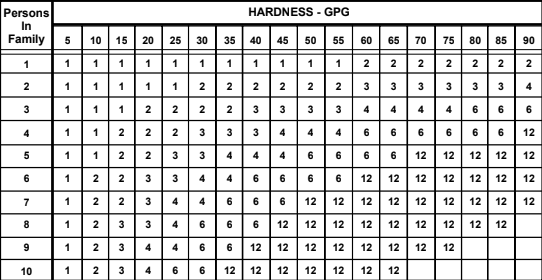
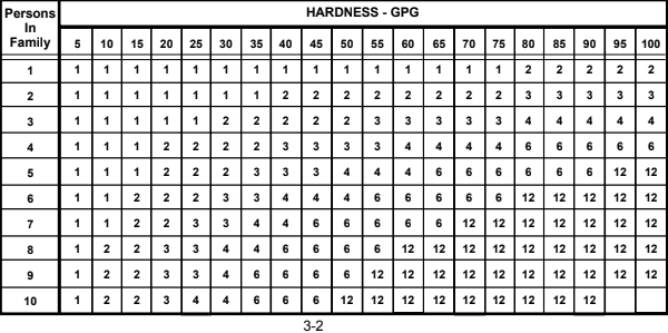
INSTRUCTIONS FOR USING REGENERATION FREQUENCY SCHEDULES:
(Time Clock Initiated Models Only)
(1) Determine ADJUSTED HARDNESS by adding three (3) times the iron content in parts per million (ppm) to the hardness in grains per gallon (gpg). The resulting number is ADJUSTED HARDNESS.
EXAMPLE: Hardness is 14 gpg and iron is 2 ppm. ADJUSTED HARDNESS is 20 gpg (14 plus 3 times 2).
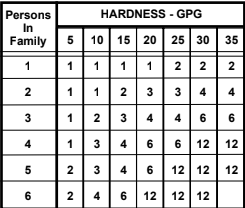
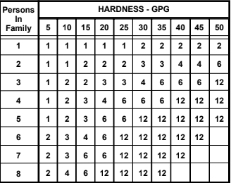
(2) Select REGENERATION FREQUENCY SCHEDULE corresponding to your model. Locate box intersected by NUMBER IN FAMILY and ADJUSTED HARDNESS (if 3-1ADJUSTED HARDNESS is between two numbers in schedule, use higher number). Number in box repre-
sents FREQUENCY or NUMBER OF times per 12 DAYS timer should be set to regenerate. Refer to HOW TO SET TIME CLOCK REGENERATION CONTROL to set correct frequency.
EXAMPLE: You have Model NS1000, 4 in family and 20 gpg adjusted hardness. Refer to REGENERATION FREQUENCY SCHEDULE for Model Series 1000 and locate box intersected by 4 in family and 20 gpg adjusted hardness. The figure “3” in box indicates a REGENERATION frequency of THREE TIMES PER 12 DAYS (if a “1”, “2”, “4”,etc. were in box, frequencies of once, twice and four times per twelve days, respectively, would be indicated.)
REGENERATION FREQUENCY SCHEDULES
(TIMES PER 12 DAYS)
HOW TO SET TIME CLOCK REGENERATION CONTROL
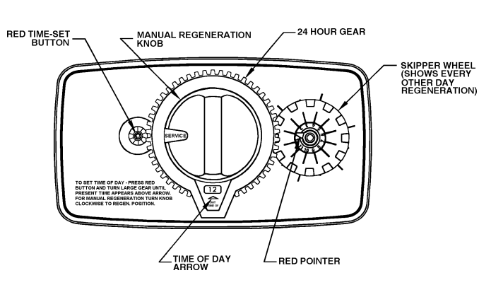
HOW TO SET DAYS ON WHICH WATER SOFTENER IS TO REGENERATE:
Rotate the skipper wheel until the number “1” is at the red pointer. Set the days that regeneration is to occur by sliding tabs on the skipper wheel outward to expose trip fingers. Each tab is one day. Finger at red pointer is tonight. Moving clockwise from the red pointer, extend or retract fingers to obtain the desired regeneration schedule.
HOW TO SET THE TIME OF DAY:
(1) Press and hold the red button in to disengage the drive gear.
(2) Turn the large gear until the actual time of day is opposite the time of day pointer.
(3) Release the red button to again engage the drive gear.
(4) Time of regeneration is preset for 2:00 a.m.
HOW TO MANUALLY REGENERATE YOUR WATER SOFTENER AT ANY TIME.
Turn the manual regeneration knob clockwise.
A slight, clockwise movement of the manual regeneration knob engages the program wheel and starts the regeneration program.
The black center knob will make one revolution in the following approximately three hours and stop in the position shown in the drawing (SERVICE POSITION).
Even though it takes three hours for this center knob to complete one revolution, the regeneration cycle of your unit might be set only one-third of this time.
In any event, conditioned water may be drawn after rinse water stops flowing from the water softener drain line.
HOW TO SET METER REGENERATION CONTROL
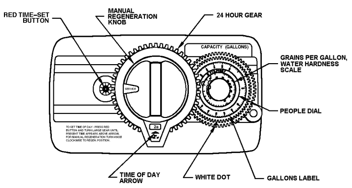
TYPICAL RESIDENTIAL APPLICATION:
To program, just set the time, set the hardness and it automatically monitors system needs and regenerates only when necessary. To set time of day, press red time set button and turn 24-hour gear until present time of day is opposite “time of day arrow.” Set program wheel by lifting the “people” dial and rotating it so that the number of people in the household is aligned with the grains per gallon water hardness (adjusted hardness*) scale. Release the dial and check for firm engagement at setting. (This method will provide reserve capacity of one day’s supply based on 75 gallons per person.)
OPTIONAL PROGRAMMING PROCEDURE:
Calculate the gallon capacity of the system, subtract the necessary one day’s reserve requirement and set the gallons available opposite the small white dot on the program wheel gear. Note: drawing shows 850 gallon setting. The capacity (gallons) arrow denotes remaining gallons exclusive of fixed reserve.
HOW TO SET THE TIME OF DAY:
(1) Press and hold the red button in to disengage the drive gear.
(2) Turn the large gear until the actual time of day is opposite the time of day pointer.
(3) Release the red button to again engage the drive gear.
HOW TO MANUALLY REGENERATE YOUR WATER SOFTENER AT ANY TIME:
A slight, clockwise movement of the manual regeneration knob engages the program wheel and starts the regeneration process.
The black center knob will make one revolution in the following approximately three hours and stop in the position shown in the drawing.
Even though it takes three hours for this center knob to complete one revolution, the regeneration cycle of your unit might be set for only one-third of this time.
In any event, conditioned water may be drawn after rinse water stops flowing from the water conditioner drain line.
NOTE: The backside of the timer is set the same as the standard time clock regenerated models.
- Adjusted hardness equals hardness in grains per gallon (gpg) plust 3 times the iron in parts per million (ppm).
SERVICE INSTRUCTIONS
| PROBLEM | CAUSE | SOLUTION |
| 1.Hard water, (unit NOT using salt; liquid level in brine tank NOT too high). | A. Electrical service to unit interrupted. B. Timer not working. C. Timer improperly set. D. Safety brine valve not opening. E. Salt “bridged” in brine tank. | A. Assure permanent electrical service (check fuse, plug, pull chain or switch.) B. Replace timer motor. C. Increase frequency of regeneration and/or salt setting. D. Replace safety brine valve. E. Breakup salt. |
| 2.Hard water, (unit using salt; liquid level in brine tank NOT too high). | A. Bypass open. B. Timer improperly set. C. No salt in brine tank. D. Excessive water usage. E. Unit installed backwards. F. Unit undersized. | A. Close bypass (replace if necessary). B. Increase frequency of regeneration, or reset timer if needed. C. Add salt; maintain above water level. D. Increase frequency of regeneration and/or salt setting (See HOW TO SET TIMER). E. Reinstall unit. F. Replace with larger unit. |
| 3.Liquid level in brine tank TOO high. | A. Brine valve not closing. B. Salt setting too high. C. Injector screen plugged. D. Drain line frozen, plugged or restricted. E. Salt “mushed” or sand from salt plugging bottom of brine tank. F. Incorrect brine line flow control (BLFC). | A. Replace brine valve. B. Reset timer. C. Clean injector and screen. D. Free drain. E. Clean out brine tank (See Instructions). F. Replace with correct flow control (See Specifications). |
| 4.System regenerates at wrong time-of-day. | A. Power outage occurred. | A. Reset timer. |
| 5.Water continuously flows to drain. | A. Foreign material in control valve. B. Internal control leak. C. Control valve jammed in brine or backwash position. | A. Remove piston assembly and inspect bore; remove foreign material and check control in various regenera- tion positions. B. Replace seals and/or piston assembly. C. Replace piston, seals and spacers. |
| 6.Water tastes salty. | A. Salt setting too high. B. Cyclone (distributor) tube too short. | A. Reset program cycle. B. Replace. |
| 7.White spots on glassware and dark surfaces. | A. Sodium residual resulting from water having very high hardness or total dissolved solids (TDS). | A. Installation of additional water treatment equipment such as reverse osmosis or demineralization. |
| 8.Low water pressure (low flow rate). | A. Iron build-up in line to water conditioner. B. Iron build-up in water conditioner. C. Well pumping sand. D. Pump losing capacity. | A. Clean line to water conditioner. B. Clean control and add Iron-XTM Mineral Cleaner to resin bed; increase frequency of regeneration. C. Install sand trap. D. Contact pump repair service. |
| 9.”Rotten egg” smell (from hot water ONLY). | A. Magnesium rod in water heater. | A. Replace with aluminum rod or remove. |
| 10.”Rotten egg” smell (from both hot and cold water). | A. Hydrogen sulfide (“sulfur”) in water supply. B. Bacterial iron in water supply. C. Algae in water supply. | A. Install Sulfur Removal System. B. Install Chem-FreeTM Iron Removal System. C. Pour approximately 1/2 cup laundry bleach into brine well just before regeneration as frequently as necessary. |
| 11.Loss of resin through drain line. | A. Air in water system. B. Incorrect Drain Line Flow Control (DLFC). | A. Assure that well system has proper air eliminator control; check for dry well condition. B. Replace with correct DLFC. |
SPECIFICATIONS AND OPERATING DATA
TIMER INITIATED MODELS:
| ITEM | NS0751 | NS1001 | NS1501 | NS2001 | NS2501 | NLS0501 | NLS0751 | NLS1001 |
| System Style: | TWO TANK | SPACEMAKER | ||||||
| Nominal Media Volume, cu. ft. | 0.75 | 1.0 | 1.5 | 2.0 | 2.5 | 0.5 | 0.75 | 1.0 |
| Salt dosage, lbs.: Factory Setting Maximum Setting | 6.0 12.0 | 6.0 15.0 | 9.0 24.0 | 12.0 24.0 | 15.0 24.0 | 6.0 8.0 | 6.0 12.0 | 6.0 15.0 |
| Nominal Softening Capacity, grains: (1) At factory salt setting At maximum salt setting | 21,450 22,500 | 18,600 30,000 | 27,900 45,000 | 37,200 54,000 | 46,500 60,000 | 14,300 15,000 | 21,450 22,500 | 18,600 30,000 |
| Operating Flow Rates, gpm: (2) Continuous (no duration limit) Service (10 minutes or less) | 3.0 6.0 | 4.0 7.0 | 6.0 8.0 | 7.0 8.5 | 9.0 10.0 | 2.0 4.0 | 3.0 6.0 | 4.0 7.0 |
| Pressure Loss @ Operating Flow Rates, psi: Continuous Service | 6.0 10.0 | 6.0 15.0 | 8.0 15.0 | 9.0 15.0 | 11.0 15.0 | 5.0 8.0 | 6.0 10.0 | 6.0 15.0 |
| Regeneration Flow Rates, gpm: Backwash (3) Brine/Rinse Rapid Rinse Brine Refill | 1.2 0.26 1.2 0.5 | 1.5 0.33 1.5 0.5 | 2.4 0.33 2.4 0.5 | 2.4 0.33 2.4 0.5 | 3.5 0.64 3.5 0.5 | 1.2 0.26 1.2 0.5 | 1.5 0.33 1.5 0.5 | 2.0 0.33 2.0 0.5 |
| Inlet/Outlet Pipe Size, in. | 3/4 or 1 | 3/4 or 1 | 3/4 or 1 | 3/4 or 1 | 3/4 or 1 | 3/4 or 1 | 3/4 or 1 | 3/4 or 1 |
| Mineral Tank Dia. x Height, in. | 7×44 | 8×44 | 10×44 | 10×54 | 12×54 | 7×35 | 8×35 | 10×35 |
| Overall Depth & Height w/Control Valve, in. | 15×51 | 15×51 | 15×51 | 15×61 | 15×61 | 15×42 | 15×42 | 15×42 |
| Brine Tank, W x D x H, in. | 15x15x34 | 15x15x34 | 15x15x34 | 15x15x34 | 15x15x34 | 15x15x34 | 15x15x34 | 15x15x34 |
| Approx. Salt Storage, lbs. | 160 | 160 | 160 | 160 | 160 | 160 | 160 | 160 |
| Approx. Shipping Weight, lbs. | 75 | 89 | 116 | 141 | 187 | 59 | 74 | 85 |
Maximum operating temperature 100°F (38°C); Electrical requirements 110V/60Hz (220V/50Hz); Operating pressure 20- 125 psi. All types water softener salt may be used (See MAINTENANCE). Specifications subject to change without notice.
NOTES:
(1) Actual capacity may vary substantially depending on water analysis and operating conditions. Softening capacities for systems containing 0.5 and 0.75 cubic feet are based on SOFTENING PERFORMANCE, systems containing 1.0 cubic feet and larger are based on Radium 226/228, Barium and Softening.
(2) For satisfactory performance indicated flow rates and duration should not be exceeded. Flow rates specified are adequate for normal residential applications. Do not use Service Flow Rate when sizing commercial applications or if treated water is to supply a geothermal
heat pump, swimming pool, etc. (contact dealer before selecting equipment).
(3) For system to operate properly, pumping rate of well pump MUST be sufficient to backwash unit at rate specified.
(4) Model numbers ending with “1” are 1 in.; those ending with “0” are 3/4 in. Example: NS1001 becomes NS1000.
METER INITIATED MODELS:
| ITEM | NSM0751 | NSM1001 | NSM1501 | NSM2001 | NSM2501 | NLSM0751 | NLSM1001 |
| System Style: | TWO TANK | SPACEMAKER | |||||
| Nominal Media Volume, cu. ft. | 0.75 | 1.0 | 1.5 | 2.0 | 2.5 | 0.75 | 10 |
| Salt dosage, lbs.: Factory Setting (1) Maximum Setting | 6.0 12.0 | 6.0 15.0 | 9.0 24.0 | 12.0 24.0 | 15.0 24.0 | 6.0 12.0 | 6.0 15.0 |
| Nominal Softening Capacity, grains:(2) At factory salt setting At maximum salt setting | 21,450 22,500 | 18,600 30,000 | 27,900 45,000 | 37,200 54,000 | 46,500 60,000 | 21,450 22,500 | 18,600 30,000 |
| Operating Flow Rates, gpm: (3) Continuous (no duration limit) Service (10 minutes or less) | 3.0 6.0 | 4.0 7.0 | 6.0 8.0 | 7.0 8.5 | 9.0 10.0 | 3.0 6.0 | 4.0 7.0 |
| Pressure Loss @ Operating Flow Rates, psi: Continuous Service | 6.0 10.0 | 6.0 15.0 | 8.0 15.0 | 9.0 15.0 | 11.0 15.0 | 6.0 10.0 | 6.0 15.0 |
| Regeneration Flow Rates, gpm: Backwash (4) Brine/Rinse Rapid Rinse Brine Refill | 1.2 0.26 1.2 0.5 | 1.5 0.33 1.5 0.5 | 2.4 0.33 2.4 0.5 | 2.4 0.33 2.4 0.5 | 3.5 0.64 3.5 0.5 | 1.5 0.33 1.5 0.5 | 2.0 0.33 2.0 0.5 |
| Inlet/Outlet Pipe Size, in. (5) | 3/4 or 1 | 3/4 or 1 | 3/4 or 1 | 3/4 or 1 | 3/4 or 1 | 3/4 or 1 | 3/4 or 1 |
| Mineral Tank Diameter x Height, in. | 7 x 44 | 8 x 44 | 10 x 44 | 10 x 54 | 12 x 54 | 8 x 35 | 10 x 35 |
| Overall Depth & Height w/Control Valve, in. | 17 x 51 | 17 x 51 | 17 x 51 | 17 x 61 | 17 x 61 | 17x 42 | 17x 42 |
| Brine Tank, W x D x H, in. | 15x15x34 | 15x15x34 | 15x15x34 | 15x15x34 | 15x15x34 | 15x15x34 | 15x15x34 |
| Approx. Salt Storage, lbs. | 160 | 160 | 160 | 160 | 160 | 160 | 160 |
| Approx. Shipping Weight, lbs. | 76 | 90 | 117 | 142 | 188 | 75 | 86 |
Maximum operating temperature 100°F (38°C); Electrical requirements 110V/60Hz (220V/50Hz); Operating pressure 20- 125 psi. All types water softener salt may be used (See MAINTENANCE). Specifications subject to change without notice.
NOTES:
(1) Dial settings based on this capacity. Consult dealer before changing salt dosage.
(2) Actual capacity may vary substantially depending on water analysis and operating conditions. Softening capacities for systems containing 0.5 and 0.75 cubic feet are based on SOFTENING PERFORMANCE, systems containing 1.0 cubic feet and larger are based on Radium 226/228, Barium and Softening.
(3) For satisfactory performance indicated flow rates and duration should not be exceeded. Flow rates specified are adequate for normal residential applications. Do not use Service Flow Rate when sizing commercial applications or if treated water is to supply a geothermal
heat pump, swimming pool, etc. (contact dealer before selecting equipment).
(4) For system to operate properly, pumping rate of well pump MUST be sufficient to backwash unit at rate specified.
(5) Model numbers ending with “1” are 1 in. those ending with “0” are 3/4 in. Example: NSM1001 becomes NSM1000.
PARTS
COMPONENT PARTS LIST
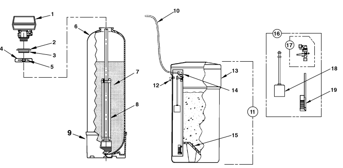
TWO TANK MODELS (NS & NSM SERIES)
| REF NO. | DESCRIPTION | NS0751 NSM0751 | NS1001 NSM1001 | NS1501 NSM1501 | NS2001 NSM2001 | NS2501 NSM2501 |
| 1 | Control Valve, Time Clock Initiation, with Cover, less Bypass (NS Series) Control Valve, Meter Initiation, with Cover, less Bypass (NSM Series) | N100120-5R N12J120-5R | N100150-5W N12J150-5W | N100240-5W N12N240-5W | N100240-5W N12R240-5W | N100350-5W N12U350-5W |
| 2 | Adapter Assy., Flg-Thrd (Incl. Ref. 3) | FA45TX | FA45TX | FA45TX | FA45TX | FA45TX |
| 3 | O-Ring | ORG-234 | ORG-234 | ORG-234 | ORG-234 | ORG-234 |
| 4 | Clamp Assy. (Incl. Ref. 5) | FC45XX | FC45XX | FC45XX | FC45XX | FC45XX |
| 5 | Latch, Clamp | FC45C | FC45C | FC45C | FC45C | FC45C |
| 6 | Media Tank w/Base (Incl. Ref. 9) | MTP0744FB | MTP0844FB | MTP1044FB | MTP1054FB | MTP1254FB |
| 7 | Media | H-075P | H-10P | H-10P & H-050P | H-10P(x2) | H-10P(x2) & H-050P |
| 8 | Cyclone Assy. | C04N-44 | C04N-44 | C04N-44 | C04N-54 | C04N-54 |
| 9 | Tank Base | T06-7P | T06-8P | T06-10P | T06-10P | T06A-12P |
| 10 | Brine Line Tubing | 13000X | 13000X | 13000X | 13000X | 13000X |
| 11 | Brine Tank, Complete Brine Tank, Complete w/Extension Kit | BT1534X __ | BT1534X __ | BT1534X __ | __ BT1534X-EXT | __ BT1534X-EXT |
| 12 | Overflow Fitting | BT16 | BT16 | BT16 | BT16 | BT16 |
| 13 | Brine Tank Shell w/Cover | BT1534L | BT1534L | BT1534L | BT1534L | BT1534L |
| 14 | Brine Well w/Cap | BT15BW | BT15BW | BT15BW | BT15BW | BT15BW |
| 15 | Grid Plate Grid Plate w/Extension Kit | BT15GP __ | BT15GP __ | BT15GP __ | __ BT15GP-EXT | __ BT15GP-EXT |
| 16 | Safety Brine Valve, Complete | BT15SBVA | BT15SBVA | BT15SBVA | BT15SBVA | BT15SBVA |
| 17 | Safety Brine Valve | 60014 | 60014 | 60014 | 60014 | 60014 |
| 18 | Float Assembly | 60068X | 60068X | 60068X | 60068X | 60068X |
| 19 | Air Check Assembly | 60002 | 60002 | 60002 | 60002 | 60002 |
NOTE: When ordering components, always specify model number.
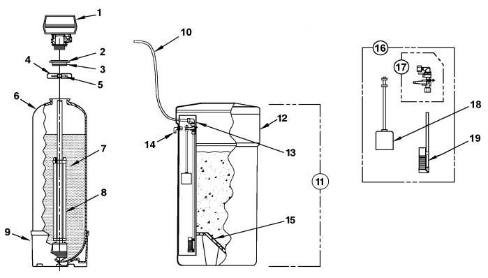
SPACE-MAKER MODELS (NLS & NLSM SERIES)
| REF NO. | DESCRIPTION | NLS0501 | NLS0751 NLSM0751 | NLS1001 NLSM1001 |
| 1 | Control Valve, Time Clock Initiation, with Cover, less Bypass (NLS Series) Control Valve, Meter Initiation, with Cover, less Bypass (NLSM Series) | N100120-5R N/A | N100150-5W N12J150-5W | N100240-5W N12J240-5W |
| 2 | Adapter Assy., Flange-Thread (Incl. Ref. 3) | FA45TX | FA45TX | FA45TX |
| 3 | O-Ring | ORG-234 | ORG-234 | ORG-234 |
| 4 | Clamp Assy. (Incl. Ref. 5) | FC45XX | FC45XX | FC45XX |
| 5 | Latch, Clamp | FC45C | FC45C | FC45C |
| 6 | Media Tank w/Base (Incl. Ref. 9) | MTP0735FB | MTP0835FB | MTP1035FB |
| 7 | Media | H-050P | H-075P | H-10P |
| 8 | Cyclone Assy. | C04N-35 | C04N-35 | C04N-35 |
| 9 | Tank Base | T06-7P | T06-8P | T06-10P |
| 10 | Brine Line Tubing | 13000X | 13000X | 13000X |
| 11 | Brine Tank, Complete | BT1534X | BT1534X | BT1534X |
| 12 | Brine Tank Shell w/Cover | BT1534L | BT1534L | BT1534L |
| 13 | Brine Well w/Cap | BT15BW | BT15BW | BT15BW |
| 14 | Overflow Fitting | BT16 | BT16 | BT16 |
| 15 | Grid Plate | BT15GP | BT15GP | BT15GP |
| 16 | Safety Brine Valve, Complete | BT15SBVA | BT15SBVA | BT15SBVA |
| 17 | Safety Brine Valve | 60014 | 60014 | 60014 |
| 18 | Float Assembly | 60068X | 60068X | 60068X |
| 19 | Air Check Assembly | 60002 | 60002 | 60002 |
NOTE: When ordering components, always specify model number.
CONTROL VALVE 12 DAY TIMER
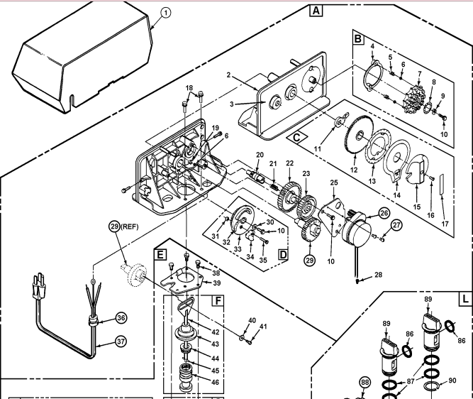
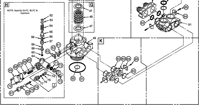
ONLY THOSE PARTS CIRCLED IN DRAWING AND/OR LISTED BELOW ARE STOCK ITEMS ALL OTHERS ARE SPECIAL ORDER, NON-RETURNABLE
PARTS LIST – 12 DAY TIMER
| REF. | PART NO. | DESCRIPTION |
| A B C D E F G H J K L | 60353-13 14381X 13010X 13168-36X 14449-00X 60102-00 60125 60084-50X 60022-50 10090X 60049/18706X 60049/18706-02X | Power Head Assy., Complete, L/Cover, NS/NLS Series (Incl. Ref. Items 2-37) Skipper Wheel Assy. (Incl. Ref. Items 4-10) 24-Hour Gear Assy. (Incl. Ref. Items 11-17) Brine Cam Assy. 6-36 lb. Salt (Incl. Ref. Items 10, 30 through 35) Control Valve Body Assy. (Incl. Ref. Items 38-81) Piston Kit (Incl. Ref. Items 42-46) Seal Kit (Incl. Ref. Items 47 & 48) Brine Valve Assy., 0.50 GPM (Incl. Ref. Items 52-81) Brine Line Flow Control Assy., 0.50 GPM, (Incl. Ref. Items 74-77) Adapter Coupling Assy. (Incl. 2 ea. Ref. Items 83-85 & 4 ea. Item 82) 1″ Bypass Valve Assy. 3/4″ Bypass Valve Assy. (Optional) |
| 1 26 27 29 36 37 50 51 61 62 63 65 66 67 68 69 70 71 | 22601X 18743 11384 13170 13547 11842 13304 12281 13497 12638 13301 10914 10227 10913 13303 13166 13315 | Valve Cover, Specify Model Motor, 120v/60 Hz Motor Mtg. & Ground Screw Main Gear Strain Relief Power Cord, 110V 60Hz Distributor Tube O-Ring Tank O-Ring Air Disperser Drain O-Ring Injector O-Ring Injector Throat – Specify Size Injector Screen Injector Nozzle – Specify Size Injector Cover O-Ring Injector Cover Injector Mounting Screw Drain Line Flow Control Button: |
72 73 78 79 80 81 82 83 84 85 88 | 12085 12086 12088 12090 13173 12338 12767 10332 10330 10329 13305 13709 13255 13314 18706 18706-02 | 1.2 GPM (0501 & 0751 Two Tank) 1.5 GPM (0751 Space-Maker, 1001 Two Tank) 2.4 GPM (1001 Space-Maker, 1501 & 2001 Two Tank) 3.5 GPM (2501 Two Tank) Drain Line Flow Control Retainer Drain Line Fitting Brine Line Screen Brine Line Tube Insert Brine Line Ferrule Brine Line Fitting Nut Adapter Coupling O-Ring Adapter Coupling Adapter Clip Adapter Coupling Screw Adapter Yoke, 1″ NPT Adapter Yoke, 3/4″ NPT |
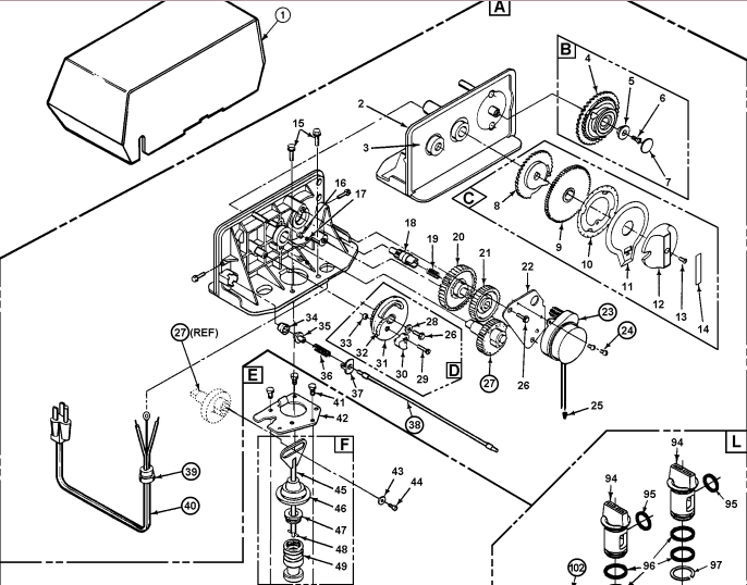
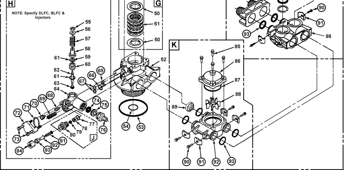
ONLY THOSE PARTS CIRCLED IN DRAWING AND/OR LISTED BELOW ARE STOCK ITEMS ALL OTHERS ARE SPECIAL ORDER, NON-RETURNABLE
| REF. | PART NO. | DESCRIPTION |
| A B C D E F G H J K L | 60354-13 14039X 13010X 13168-36X 14449-00X 60102-00 60125 60084-50X 60022-50 60086 60049/18706X 60049/18706-02X | Power Head Assy., Complete, L/Cover, NSM/NLSM Series (Incl. Ref. Items 2-40) Program Wheel Assy. (Incl. Ref. Items 4-7, Specify “K” Label or Model) 24-Hour Gear Assy. (Incl. Ref. Items 8-14) Brine Cam Assy. 6-36 lb. Salt (Incl. Ref. Items 26, 28-33) Control Valve Body Assy. (Incl. Ref. Items 41-84) Piston Kit (Incl. Ref. Items 45-49) Seal Kit (Incl. Ref. Items 50 & 51) Brine Valve Assy., 0.50 GPM (Incl. Ref. Items 55-84) Brine Line Flow Control Assy., 0.50 GPM, (Incl. Ref. Items 77-80) Meter Assy. (Incl. Ref. Items 85-93) 1″ Bypass Valve Assy. 3/4″ Bypass Valve Assy. (Optional) |
| 1 23 24 27 38 39 40 53 54 65 66 67 68 69 70 71 72 73 74 | 22601X 18743 11384 13170 14043 13547 11842 13304 12281 13497 12638 13301 10914 10227 10913 13303 13166 13315 | Valve Cover, Specify Model Motor, 120v/60 Hz Motor Mtg. & Ground Screw Main Gear Flexible Cable Strain Relief Power Cord, 110V/60Hz Distributor Tube O-Ring Tank O-Ring Air Disperser Drain O-Ring Injector O-Ring Injector Throat – Specify Size Injector Screen Injector Nozzle – Specify Size Injector Cover O-Ring Injector Cover Injector Mounting Screw Drain Line Flow Control Button: |
75 76 81 82 83 84 90 91 92 93 102 | 12085 12086 12088 12090 13173 13308 12767 10332 10330 10329 13314 13255 13821 13305 18706 18706-02 | 1.2 GPM (0751 Two Tank) 1.5 GPM (0751 Space-Maker, 1001 Two Tank) 2.4 GPM (1001 Space-Maker, 1501 & 2001 Two Tank) 3.5 GPM (2501 Two Tank) Drain Line Flow Control Retainer Drain Line Fitting Brine Line Screen Brine Line Tube Insert Brine Line Ferrule Brine Line Fitting Nut Adapter Coupling screw Adapter Clip Meter Body Meter Body O-ring Adapter Yoke, 1″ NPT |
MAINTENANCE
REPLENISHMENT OF SALT SUPPLY:
The salt storage capacity of the brine tank is approximately 160 lbs. During each regeneration a specific amount of salt is consumed, thus requiring its periodic replenishment (the frequency is dependent on the regeneration schedule). Always replenish salt before the supply is exhausted to assure a continuous supply of softened water.
TYPE OF SALT TO USE:
Any type of water softener salt may be used. There are advantages and disadvantages to every type of salt. Please ask your local dealer for his advice. Your unit is designed to compensate for the disadvantages.
BRINE TANK CLEAN-OUT:
To prevent service problems the brine tank should be emptied and flushed out with a garden hose when dirt and other insolubles accumulate. The clean-out frequency depends on the type salt used and regeneration frequency. The clean-out should be done when the salt level is low. Steps to follow:
(1) Disconnect brine line at either end.
(2) Turn brine tank upside down and discard old salt.
(3) Rinse out with a garden hose.
(4) Reconnect brine line.
(5) Add about 3 gals. of water (6 gals. for units with extended grid legs) to brine tank before adding new salt. Perform approximately once a year if rock salt is used; with other types of salt, approximately once every other year.
PREVENTING IRON-FOULING OF MINERAL BED:
If iron is present in the water supply, the softener mineral bed will eventually become iron-fouled, resulting in reduced softening capacity and rust-stained fixtures. Mixing one to two ounces of IRON-XTM Mineral Cleaner with every 80 lbs. of salt added to brine tank will minimize these problems from occurring. IRON-XTM is available from your dealer.
PERIODICALLY CHECK TIME OF DAY SETTING:
Power outages will cause TIME OF DAY timer setting to become incorrect. To reset, refer to appropriate HOW TO SET TIME CLOCK (or METER) REGENERATION CONTROL, Section 3.
MALFUNCTION OF UNIT:
Your water softener, under normal conditions, should provide years of trouble-free service; however, since it is a mechanical device, it can malfunction. (Refer to Section 4, SERVICE INSTRUCTIONS, if necessary).
CHANGE OF OPERATING CONDITIONS:
Should your family size, your water usage habits, or your water quality change, the regeneration program settings may have to be adjusted. Consult your dealer if any of the above occur.
READ ALSO: Culligan® High Efficiency Automatic Water Softener User’s Manual
FIVE YEAR LIMITED WARRANTY
GENERAL CONDITIONS
Damage to any part of this water conditioner because of misuse, misapplication, neglect, alteration, accident, installation or operation contrary to our printed instructions, or damage caused by freezing, flood, vacuum, fire or Act of God, is not covered by this warranty. In all such cases, regular parts and service charges will apply.
We assume no warranty liability in connection with this water conditioner other than specified herein. This warranty is in lieu of all other warranties, expressed or implied, including warranties of fitness for a particular purpose. We do not authorize any person or representative to assume for us any other obligations on the sale of this water conditioner.
Should a defect or malfunction occur, contact your dealer. If you are unable to contact your dealer, return the part, freight prepaid, directly to the factory (address below). Enclose with the part a full description of the problem, with your name, full address, date purchased,
model and serial number and selling dealer’s name and address. We will repair or replace the part and return it to you at no cost if our repair department determines it to be defective under the terms of this warranty.
WARRANTY POLICY
Cuno Water Treatment, Churubusco, Indiana warrants this water conditioner as stated herein:
From the date of installation, we will repair or replace any part, within the warranty period described below, which we find defective because of faulty materials or workmanship or corrosion. You pay only freight to our factory and local labor charges.
• ONE YEAR ON ENTIRE UNIT
• FIVE YEARS ON MINERAL TANK EXCLUDING MINERAL
• THREE YEARS ON COMPLETE CONTROL VALVE
• FIVE YEARS ON CONTROL VALVE EXCLUDING INTERNAL AND ELECTRICAL PARTS
• FIVE YEARS ON SALT STORAGE CONTAINER AND BRINE VALVE COMPONENTS .
Date Purchased ________Model No. ________ Serial No. ________
Name of Original Purchaser ________
Address of Original Installation ________
City ________ State ________
Dealer Purchased From ________
Dealer Address ________
You can download the PDF version of the MACCLEAN NS/NLS SERIES RESIDENTIAL WATER SOFTENER USER’S MANUAL here