WARNING: Failure to follow and read all instructions before installing or operating this device may cause personal injury and/or property damage.
IN THE BOX:
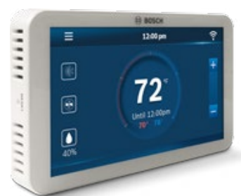
▶ BCC100 Wi-Fi Thermostat
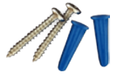
▶ Screws (2) and Anchors (2)
▶ Flathead Screwdriver
▶ Wire Labels
▶ Jumper Wire
▶ User Guide
▶ Customer Support Card
Some features require an internet connection and a user account. Features, specifications, and appearance are subject to change without notice.
A C-wire (common wire) is required to power the unit. Two wire systems are not supported. If a C-wire is not available, please contact your local Contractor for
support.
| CHECK COMPATIBILITY FIRST | |
| For conventional (gas/oil/electric) | ▶ Heat Only, Cool Only, and Combined Heat & Cool |
| For heat-pump systems | ▶ Up To 4-Heat & 2-Cool |
| Not compatible with other Bosch Boiler controls, such as the Logamatic |
Getting Started
The BCC100 thermostat is designed to work on most 24VAC low voltage heating and cooling systems such as gas and oil furnaces, heat pumps, and single or dual-stage systems.
Professional installation recommended for:
▶ Humidifiers and dehumidifiers
WARNING: Turn Off Power Failure to turn off power may result in electrical shock and/or system damage.
Turn Off Power
Please turn off the unit’s main power at the circuit panel before beginning the installation process.
1 Remove the Old Thermostat
Before removing the wires from the old thermostat, take a picture of the wiring configuration for reference, and then label each wire according to the terminal codes using the wire labels provided.
NOTE: After labeling the wires, secure them to an object such as a pen or clip to prevent them from falling back into the wall.
Disconnect the wires from the old thermostat one by one. Do not let wires fall back into the wall.
2.Mount the New Wall Plate
Use the enclosed screws and anchors to mount the new wall plate. In most cases, you can utilize the same mounting position of your old thermostat. Be sure to check the alignment of your wall plate before installation to ensure all holes are covered.
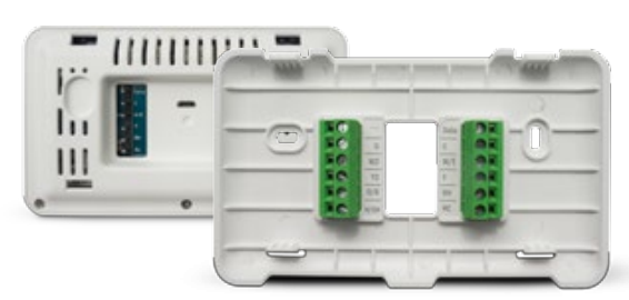
3.Connect the New Wall Plate
CAUTION: To prevent possible shorts to adjacent terminals, use care when securing and routing your thermostat wires.
Feed all wires vertically into the hole or slit in the center of the backplate. Referencing the photo of the previous wiring configuration or the wire labels currently on the wires, insert the wires one-by-one into the matching terminals, and use the supplied flathead screwdriver to close each terminal. After you have finished fastening the wires, pull each wire gently to ensure they are secure. Repeat this process for each wire to be installed.
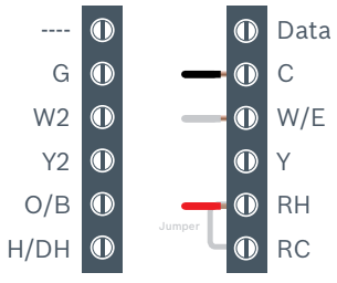
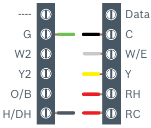
BCC100 Terminal Key
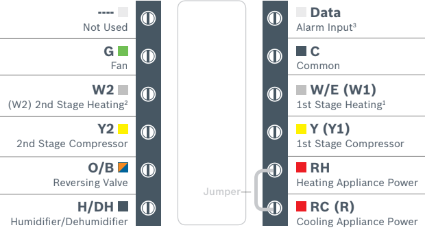
Note: The color of your wires may not be the same as shown in this User Guide (1)Emergency heat activated at W1, (2)Auxiliary heat activated at W2,
(3)Only to be used with Bosch WSHP)
NOTE: The following wiring diagrams describe some common configurations that are compatible with the BCC100. Not all compatible configurations are depicted
below. If you are unsure of how to connect your thermostat, please contact customer support using the number on the card provided in the box.
Conventional Systems
Conventional systems include furnaces, boilers, and dedicated, non-window air conditioning units.
Single Stage Heat – Boiler
- Ensure the system has a C-wire
- Ensure the pre-installed jumper wire remains between RH and RC
- Connect the R, C and W1 wires from the boiler to RH, C and W/E terminals on the wall plate, respectively
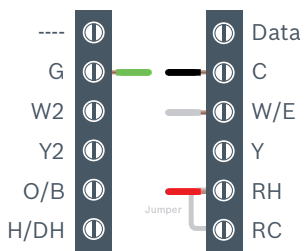
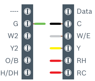
Single Stage Heat – Furnace
- Ensure the system has a C-wire
- Ensure the pre-installed jumper wire remains between RH and RC
- Connect the R, C, W1 and G wires from the Furnace to RH, C, Y and G terminals on the wall plate, respectively
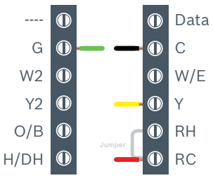
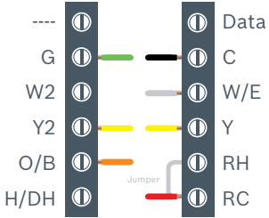
Single Stage Cool – Air Conditioner
Ensure the system has a C-wire
Ensure the pre-installed jumper wire remains between RH and RC
Connect the R, C, Y1 and G wires from the Air Conditioner to RC, C, Y and G terminals on the wall plate, respectively
Two Stage Heat – Furnance
- Ensure the system has a C-wire
- Ensure the pre-installed jumper wire remains between RH and RC
- Connect the R, C, W1, W2 and G wires from the Furnace to RH, C, W/E, W2 and G terminals on the wall plate, respectively
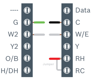
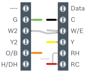
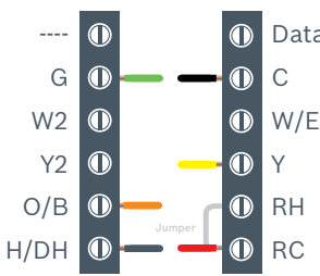
Combined Single Stage Heat and Cool Furnace and Air Conditioner ONLY
Note: combined boiler and air conditioner systems are not currently supported.
- Ensure the system has a C-wire
- Remove the pre-installed jumper wire from between RH and RC
- Connect the R, C, W1 and G wires from the Furnace to RH, C, W/E and G terminals on the wall plate, respectively
- Connect the R, C, Y1 and G wires from the Air Conditioner to RC, C, Y and G terminals on the wall plate, respectively
Heat Pump Systems
Heat pump systems are specialty designed to be able to provide heating and cooling using a single compressor, a reversing valve, and a fan
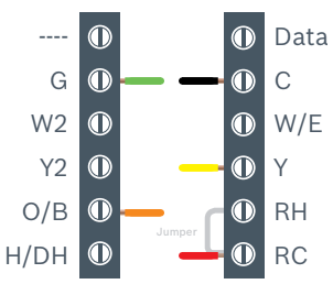
Single Stage Heat Pump
- Ensure the system has a C-wire
- Ensure the pre-installed jumper wire remains between RH and RC
- Connect the R, C, Y1, O/B and G wires from the heat pump to RC, C, Y, O/B and G terminals on the wall plate, respectively
Single Stage Heat Pump with Emergency Heat and Auxiliary Heat
Note: W/E controls the Emergency Heat output and W2 controls the Auxiliary Heat output. Therefore, a jumper is required when using the same heating source for both Emergency Heat and Auxiliary Heat.
- Ensure the system has a C-wire
- Ensure the pre-installed jumper wire remains between RH and RC
- Connect the R, C, W1, Y1, O/B and G wires from the heat pump to RC, C, W/E, Y, O/B and G terminals on the wall plate, respectively
- Connect the supplied jumper wire between the W/E and W2 terminals of the wall plate
Two Stage Heat Pump with One Stage Emergency Heat
- Ensure the system has a C-wire
- Ensure the pre-installed jumper wire remains between RH and RC
- Connect the R, C, W1, Y1, Y2, O/B and G wires from the heat pump to RC, C, W/E, Y, Y2, O/B and G terminals on the wall plate, respectively
Humidifier and Dehumidifier Accessory
A single Humidifier or Dehumidifier Accessory can be controlled using the BCC100. The thermostat only supports Humidifiers in heating operation, Dehumidifiers
in cooling operation, and only one accessory per thermostat.
Humidifier or Dehumidifier Accessory with a Combined Single Stage Heat and Cool Conventional System
Note: The wiring configuration for humidifiers and dehumidifiers is the same for all type of Conventional Systems.
- Ensure that the accessory is externally powered
- Ensure the Conventional System is wired correctly
- Connect the control wire of the accessory to the H/DH terminal of the wall plate
Humidifier or Dehumidifier Accessory with a Single Stage Heat Pump
Note: The wiring configuration for humidifiers and dehumidifiers is the same for all type of Heat Pump Systems
- Ensure that the accessory is externally powered
- Ensure the Heat Pump System is wired correctly
- Connect the control wire of the accessory to the H/DH terminal of the wall plate
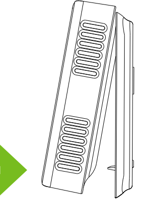
4.Attach BCC100 to the Wall Plate
1.Align the two clips on the back of the BCC100 into the corresponding slots on the top of the wall plate.
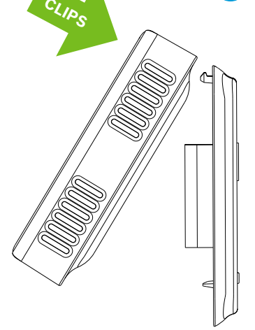
2.Firmly press forward until you hear a click to secure the thermostat into position.
Switch on the power to the heating/cooling system at the main switch box. If the thermostat does not power on, remove the BCC100 from the wall and ensure the RH/RC wire(s) and C-wire are correctly connected to both the appliance and the thermostat.
5.Enjoy the experience of the product!
When your thermostat powers on, it prompts you to start the setup. If you are having trouble powering the thermostat, please refer to the Customer Support
Card in the box for additional support information.
Thank you for choosing the BCC100. Enjoy the savings and comfort of owning a Bosch connected thermostat!
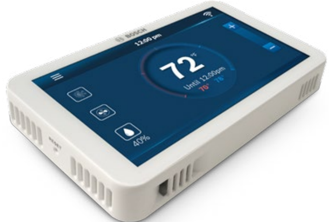
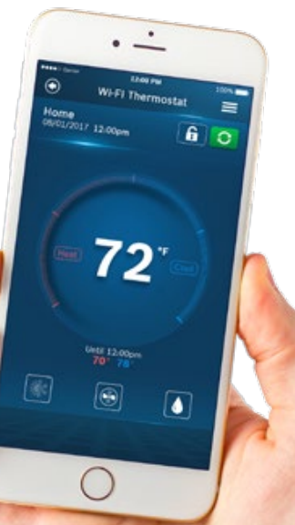
Main Screen
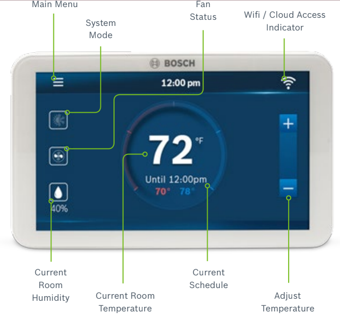
Icons
Basic Icons


System Modes


Heating Types

Propane


Fan Modes


Humidity


Unit Operation

Heating on (1st stage) & (2nd stage)
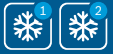
Cooling on (1st stage) & (2nd stage)
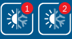
Heating on (1st stage) & (2nd stage)
Cooling on (1st stage) & (2nd stage)

Fan on/running – Fan Auto Mode

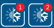
Heating
Emergency heat on

Heating
Auxiliary heat on – 2nd Aux Stage of a 4-stage heating system
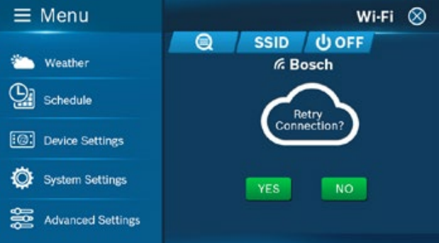
System Connectivity

Schedule on Device

Schedule on Cloud

Wi-Fi Connection Established

Wi-Fi Connection Not Established

Internet is Not Available

Retry Internet Connection
Initialization
For a quick and easy way to begin using your new smart thermostat, the device will automatically direct you to the Initial Setup screen after you have turned it on for the first time.
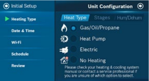
1.Unit Configuration
Select your home’s heating type, stage configuration for heating and cooling, and type of accessory (humidifier or dehumidifier) if available.
Heat Pump System
Configure the reversing valve for O (energized in cool) or B (energized in heat) and enable/disable Emergency Heat and/or Auxiliary Heat.
Humidifier & Dehumidifier Unit Configuration
When selecting a dehumidifier, you have the ability to enable or disable Cool to Dehumidify. When selecting a humidifier, you have the ability to choose between either a steam or evaporative type. Enabling this feature will allow the thermostat to control an external dehumidifier accessory, while disabling this feature will allow the thermostat to control specific appliances, such as Bosch Water Source Heat Pumps equipped with Hot Gas Reheat coils and/or ECM motors, with just an H/DH call.
NOTE: If you do not know which operation to choose, check your heating/cooling system manual or consult a professional HVAC technician.
2.Date & Time
ON DEVICE: Enter your location’s current date and time; after the device is registered or linked to a user account, the date and time on the device will automatically update to the current time associated with the user account.
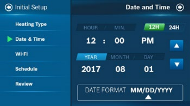
APP: The date and time for the device, as well as the user account, will automatically update by selecting the time zone for the device.
3.Wi-Fi Setup
The BCC100 requires a reliable Wi-Fi connetion in order to access smart features such as remote access, weather forecast and more. To complete the Wi-Fi setup, follow the on-screen instructions. Additional instructions are also available on page 16 in the Wi-Fi Setup section of this User Guide.
After a successful connection, the thermostat displays the Registration screen. Follow the instructions on the screen to complete the setup. After completing the setup, download the Bosch Connected Control (BCC100) app from the App Store or Google Play. Create an account within the app and then add a device by following the on-screen instructions.
4.Schedule
During offline operations, only 2 schedules (Home and Vacation) are available. However, when a Wi-Fi connection is established, the list can be expanded up to 4 schedules.
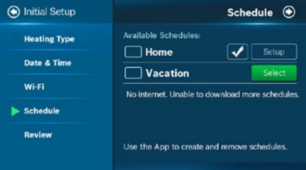
HOME: You can use this schedule to set your heating/ cooling equipment to predefined set points. The device initially comes with a factory default schedule, which can be adjusted as necessary.
VACATION: This schedule will be used to set your heating/cooling equipment to 2 periods with set points (1 heating and 1 cooling) that can be manually adjusted.
However, you will not be able to add additional or remove current periods. The schedule can be used for vacation or permanently setting a heating/cooling set point.
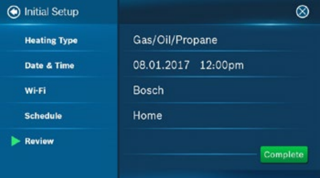
5.Review
In the final step, the BCC100 provides a review of all information that you have entered into the thermostat. You will be able to go back to different parts of the Initial Setup guide by pressing the different sections on the left pane. If you have completed the review, please press the Complete button to start utilizing your BCC100!
Wi-Fi Setup
Wi-Fi Connection
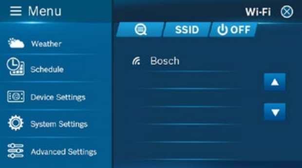
SCAN: To start Wi-Fi setup, tap the Wi-Fi icon in the top right hand corner of the main screen. Then click the Scan icon to view available Wi-Fi networks. Follow the
on-screen instructions to complete the Wi-Fi setup.
Hidden Wi-Fi Connection
MANUAL ENTRY: If you are trying to connect to a hidden network, press the SSID button to bring up the SSID screen. Enter your SSID into the text box, then follow the on-screen instruction to complete the Wi-Fi setup.

NOTE: If this is a first time installation, follow the instructions in the App Setup section of this User Guide to register your thermostat to your smart device.
The following may cause a failed connection to the device:
▶ Wi-Fi signal is too weak
▶ 5 GHz Wi-Fi network is not supported
▶ SSID contains space or non-ASCII characters
▶ Incorrect password
▶ Wi-Fi is okay but your internet is unavailable
▶ Additional web authentication is not supported
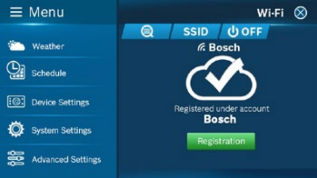
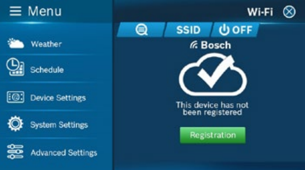
After you have successfully established a connection, your network name appears. If your thermostat is already registered to your account on your smart device, your User ID name appears.
NOTE: For all smart devices that require access to the same thermostat, you must use the same account.
For an unregistered device, click the green Registration button to register your account. If you want to register a different account to your device, you can also click the Registration button and follow the steps outlined in the App Setup section of this User Guide.
Auto Reconnect
If your device loses connection with your wireless network, it will automatically attempt to reconnect after 5 minutes. If that fails, it will make a new attempt every
15 minutes for the next 24 hours. Any manual network reconfiguration of the thermostat will stop automatic reconnection attempts.
App Setup
Congratulations! You are now connected to the thermostat. Now set up your App to enjoy additional exciting features.
Step 1: Download
| BOSCH CONNECTED CONTROL COMPATIBLE DEVICES | |
| Apple® devices running iOS 7.1 & higher | |
| Android™ devices running 4.0.3 & higher |
There are three ways to download the BCC100 App for your smart device:
▶ In the App Store or Google Play, search “Bosch Connected Control” or “BCC100” and then download the app.
▶ Use your smart device to scan the QR code below or on the packaging to be directed to the Bosch website for easy download.
▶ On your smart device, navigate to the website: www.bosch-climate.us/bcc100 and click the links for the app in the Download the App section to download.
Step 2: Create a User Account
After installing the App onto your smart phone, create a user account. After installing the App on your smart device, create a user account by clicking Register from the Login Screen. Follow the on-screen instructions to finish creating your account.
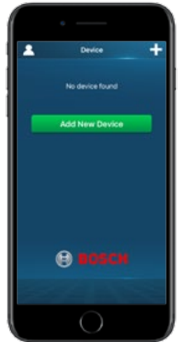
Step 3: Add Device to your Account
- Log in to your account.
- Click Add New Device.
- Follow on-screen instructions.
NOTE: You can find the MAC ID by navigating to the Wi-Fi Settings screen on your thermostat and clicking the Registration button.
MAC ID and Temporary Verification Code
You can find the MAC ID and Temporary Verification Code by navigating to the Wi-Fi Settings screen on your thermostat and clicking the Registration button.
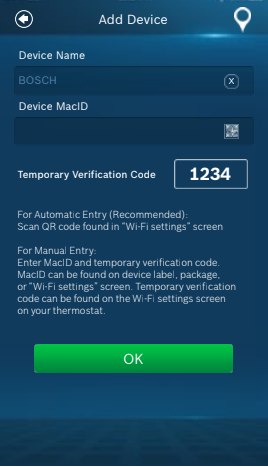
The Temporary Verification Code (TVC) is a 4-digit code randomly generated each time you enter the Registration screen on your thermostat.
The code expires after 90 seconds. If the previous code has expired, click the TVC to generate a new code.
To automatically populate the MAC ID and TVC in your App, you may use the embedded QR code in the thermostat and the QR scanner in your App’s MAC ID field.
NOTE: The MAC ID is a unique network ID that helps to identify your device over the internet. When dealing with Bosch Customer Support, the TVC functions as verification that you are in current possession of the thermostat.
Starting Your System
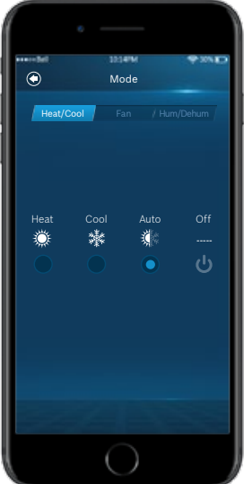
HEAT | COOL | AUTO | OFF | EM. HEAT
Tap the System Mode icon on the Home Screen to enter Mode or go to Main Menu > System Settings > Mode
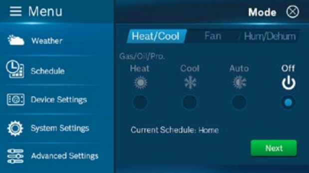
Note that your device is always running on a programmed schedule and the current operating mode is part of that schedule. Thus, when you change the Mode,
it will only change the mode for the current program. If you change to a different program, your Mode will follow the new program that you have selected.
The mode selection is for the current program (Home). You cannot assign different modes within a program.
NOTE: Em Heat (Emergency Heat) mode is only available if you have selected Heat Pump as your Heat Type and enabled the Emergency Heat function in the setup menu.
Temporary Scheduling
Temporary Adjustment
This feature will override the current set point in favor of the set point you enter until the next programmed time in the schedule. If you would like to permanently schedule the new set point, press the lock icon. This will permanently lock in the adjustment until the X button is pressed on the main screen.
Schedule Override on the Thermostat
You can override the current scheduled set point(s) by tapping the plus or minus (+/-) icons on the right side of the screen.
If you are in Auto mode, manually adjust either the Heating/Cooling set points individually.
If you are in either Heat or Cool mode, you can manually select a new temperature set point or select one of the available preset set points.
NOTE: You can change the preset temperatures from the Presets Settings Menu of the thermostat.
Schedule Override on the App
You can override the current schedule by scrolling the temperature up and down with your finger.
Programming Schedules
Programming a Schedule
When the thermostat is offline, there are only two default schedules (Home and Vacation) available for selection. If the Internet connection is established, you may have up to 4 schedules.
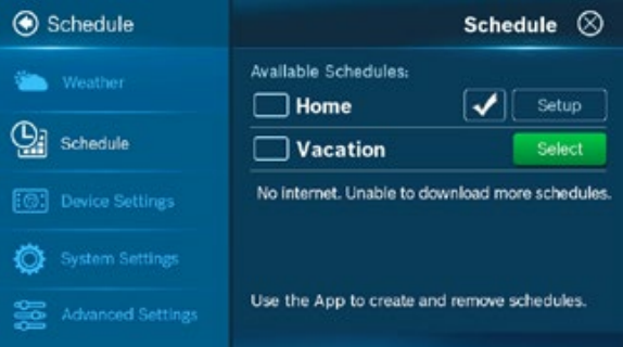
Programming with the Thermostat
You can access the Schedule by following: Menu > Schedule and selecting the schedule that you would like to run. If you want to modify the schedule, you must first select the schedule you want to modify.
- Select Schedule from the list and press the Setup button
- Select the Mode on which you want the schedule to operate, then press the Next button.
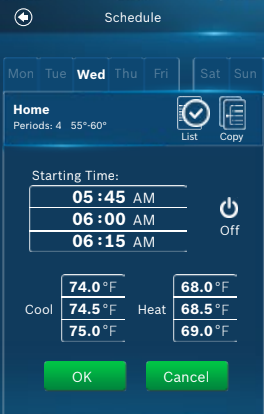
- Select the day of the week
Select the period you want to change and press the Setup button. A total of 8 periods are available per day.
- The Insert button adds a new period after the current period.
- The Delete button removes the current period.
- Set period times in 15-minute intervals. The first scheduled period is 12:00am and cannot be modified or deleted.
- Set the temperature set point(s) you want for the selected period. You can also select System Off.
- Use the Copy button to mirror the same schedule to other day(s) of the week.
Programming with the App
From the main menu in the App, select Schedule.
- Select the Mode that you would like the schedule to operate, and press Edit
- If you would like to edit a different schedule please press List for a list of available schedules
- Select the day of the week you would like to change
- Select a period (a total of 8 are available per day) to change
- Edit: Edit the current schedule
- Insert: Insert a new period after the current one
- Delete: Delete the current period
- Set period times in 15-minute intervals. The first scheduled time may not be changed from 12:00am.
- Set the temperature set point(s) you want for the selected period. You can also select the System Off.
- Use the Copy button to copy the same schedule to another day of the week
Additional Features
Weather Forecast
The weather forecast is based on the location of the installed thermostat. The first time you connect your thermostat to the app, your location was assigned to the thermostat.
NOTE: You must grant “location access” for the app to enable this feature.
Screen Options
There are 3 levels of screen brightness and 3 options for Screen Timeout.
You can also utilize this menu to Lock the screen. A 4-digit passcode will be required to lock the screen.
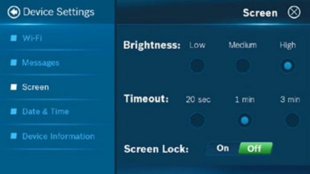
Device Information
Device information will contain all the relevant Account and System information.
Account: Change or remove the account associated with the thermostat.
System: Displays the current hardware and software information. This screen can also be used to update the firmware.
NOTE: It is important that you remember your screen lock passcode as you will not be able to unlock the screen without this code.
Unit Operating Mode
Heat: The thermostat cycles your heating appliance to maintain your scheduled heating set point.
Cool: The thermostat cycles your cooling appliance to maintain your scheduled cooling set point.
Auto: The thermostat cycles your heating/cooling appliance to maintain your scheduled heating/cooling set points.
Off: The thermostat turns off all heating/cooling functions. You can still manually operate the fan in this mode.
Emergency Heat (available only with Heat Pumps): The thermostat turns off all compressor stage(s) and activates the back-up electric heat source(s).
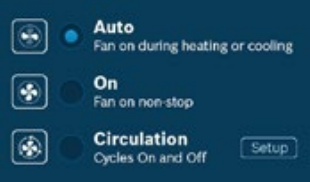
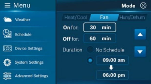
Fan Operation
Auto: Fan will follow heating and cooling operations.
On: Fan runs non-stop.
Circulation: Fan cycles on and off regularly in addition to heating and cooling operations. By selecting this option, you also need to define the operation length of time and schedule for the circulation.
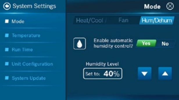
Humidifier & Dehumidifier Operating Mode
You can enable automatic humidity control if the correct humidifier or dehumidifier accessory was correctly wired and configured during the thermostat’s initial setup. Based on the setup, the thermostat turns on the humidifier during heating operation and the dehumidifier will be turned on during cooling operation. You can also configure the thermostat to operate similar to a humidistat, which runs the humidifier or dehumidifier, regardless of an active heating/cooling call.
NOTE: You may only operate in either humidifier OR dehumidifier mode and may not operate in both modes at the same time.
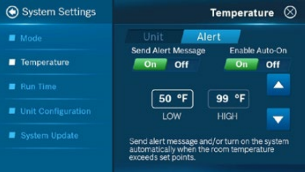
Temperature, Alerts, and Auto-On
Alert: Send an alert message or turn on the system automatically when the room temperature is out of the range between set-points.
NOTE: Alerts are an additional source of protection for your heating/cooling appliance.
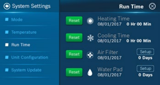
Run Time
The thermostat keeps track of your run time for the Heating, Cooling, Air Filter and Water Pad. You can also set a reminder for Air Filter and Water Pad according to the number of calendar days. When it reaches its predefined run time, the thermostat displays a notification and sends a message to the registered smart device(s).
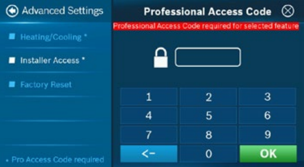
Advanced Features
Advanced Settings are designed for HVAC professionals who want to modify advanced features for better unit control. They also allow you to reset the device to factory settings.
NOTE: Advanced Settings are for professional use only and requires access code: 1886.
IP: IP Address
Ability to manually type in IP address
RS: Factory Reset
Factory reset the device to original condition
SC: Sensor Calibration
Calibrate or correct the device temperature readings
IS: Initial Setup
Pull-up Initial Setup screen
WRS: Wi-Fi Factory Reset
Factory reset the Wi-Fi module to original condition
RF: System Backup
Store current firmware in the flash to be used during recovery
HSD: Relative Humidity Hysteresis
Adjust the set point differential for the humidity control
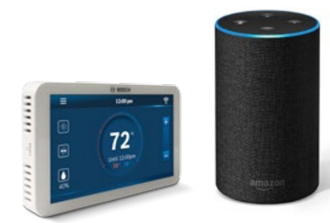
Control Your BCC100 with Amazon Alexa
Bosch offers one Smart Home Skill for integrating your BCC100 with Amazon Alexa’s voice controls. Using the Bosch Connected Control Skill from the Skills section of the Amazon Alexa App.
You Can Control the BCC100 by Saying:
▶ Alexa, turn (Device Name) on.
▶ Alexa, turn (Device Name) off.
▶ Alexa, Increase (Device Name) by _ degrees. ▶ Alexa, Decrease (Device Name) by _ degrees.
▶ Alexa, Set (Device Name) to __ degrees.
▶ Alexa, what is the (Device Name) set to?
▶ Alexa, what is the temperature of the (Device Name)?
The Device Name is the name assigned to your device in the BCC100 app. You can check the device name by opening the BCC100 app and reading the name displayed on the main menu of selectable devices.
NOTE: The Amazon Alexa commands for the BCC100 are intended for use in Heating Only and Cooling Only modes.
Connecting Your BCC100 to Amazon Alexa
- Download the BCC100 App, create an account, and register your app to the BCC100 thermostat.
NOTE: You must have a registered BCC100 account to set up and use your thermostat with Amazon Alexa.
- Download the Amazon Alexa app and set up your Alexa-enabled device.
- In the Amazon Alexa app, click on the Menu button in the top left corner.
- Click on the Skills section and search for “Bosch Connected Control” in the search bar at the top of the page.
- After you find and click on the Bosch Connected Control Skill, click on the blue Enable button.
- The setup process redirects you to a Bosch sign-in page where you will need to enter your BCC100 account username and password.
- After you have received confirmation that your two accounts have been successfully linked, click Done in the top left hand corner.
- Next click Discover Devices in the Amazon Alexa app or say “Alexa, discover new devices.” Device Discovery could take up to 45 seconds.
- When device discovery is complete, you should see a list of connected devices in the Smart Home menu of your Amazon Alexa app.
The setup process is now complete and you can start to control your BCC100 with your Alexa enabled device. Try out some of the commands above and enjoy!
Warranty
Bosch Connected Control BCC100 Thermostat
Models Covered
This limited warranty is provided by Bosch Thermotechnology Corp. (“Bosch”) and covers the Bosch Connected Control (BCC100) Wi-Fi Thermostat (hereinafter referred to as “Product”). This warranty is provided to the original purchaser of the Product as long as the Product remains installed at its original place of installation.
Warranty Coverage
Limited Warranty
Bosch warrants that the Product will remain free from defects in material and workmanship for five (5) years from the date of original installation or from the date of manufacture if proof of installation is not available, provided it is properly installed and the other conditions of this warranty are met. If Bosch determines that the Product has a defect in workmanship or materials, Bosch, at its option, will repair or replace the defective part.
Items Not Covered
This limited warranty does not cover the following circumstances:
- Components or parts not provided by Bosch.
- Components or parts, on which the tags or nameplates have been removed, altered or defaced.
- Scratches in or discoloration of finishes.
- The workmanship of any installer. Bosch disclaims and does not assume any liability of any nature for unsatisfactory performance caused by improper
installation, repair or maintenance. - Any labor or material costs for removal, reinstallation, repair and replacement of the defective component or part unless otherwise provided above.
- Electricity or fuel costs, or any increases or unrealized savings in same, for any reason whatsoever.
- Damage caused by operation of the Product in a corrosive atmosphere, electrical failures, flooding or acts of God.
- Damage caused by any attachment or modification to the Product, including any energy saving device.
- Damage caused by Product not being installed in accordance with all applicable state and local plumbing and/or building codes and regulations.
- Shipping charges, delivery expenses or administrative fees incurred by the purchaser in repairing or replacing the Product.
LIMITED WARRANTY
OTHER THAN THE OBLIGATIONS OF BOSCH EXPRESSLY SET FORTH HEREIN, BOSCH DISCLAIMS ALL WARRANTIES, EXPRESS OR IMPLIED, INCLUDING BUT NOT LIMITED TO ANY IMPLIED WARRANTIES OF MERCHANTABILITY OR FITNESS FOR A PARTICULAR PURPOSE. BOSCH’S SOLE OBLIGATION WITH RESPECT TO THE PRODUCT AND PURCHASER’S EXCLUSIVE REMEDIES ARE SET FORTH IN THE FOREGOING LIMITED WARRANTY. BOSCH SHALL NOT BE LIABLE FOR ANY INDIRECT, PUNITIVE, INCIDENTAL, SPECIAL, CONSEQUENTIAL OR SIMILAR DAMAGES INCLUDING, WITHOUT LIMITATION, INJURY OR DAMAGE TO PERSONS OR PROPERTY OR DAMAGES FOR LOSS OF USE, LOST PROFITS, INCONVENIENCE OR LOSS OF TIME. NOTE THAT ANY REPAIRED OR REPLACED PRODUCT WILL BE WARRANTED FOR ONLY THE UNEXPIRED TERM OF THE ORIGINAL WARRANTY.
Some states do not allow the exclusion of limitation of damages, or limitations on how long an implied warranty lasts, so the above limitations and exclusions may not apply to you.
WARRANTY CLAIMS PROCESS
If you have a warranty claim you should notify the heating contractor who installed your Product and ask that the contractor notify the distributor from whom the contractor purchased the Product. If this action is not possible or you don’t receive a response, contact Bosch Thermotechnology Corp. (Bosch), 50 Wentworth Avenue, Londonderry, NH 03053. To process your claim, you will need a copy of your original invoice or other proof of purchase and documentation showing the original installation date and location. The alleged defective Product must be returned to Bosch in accordance with Bosch procedure then in force for handling goods returned for the purpose of inspection to determine cause of failure (contact Bosch if you have questions regarding the return process). If Bosch determines that the returned product is defective and that this warranty applies, Bosch will furnish the repaired or replacement Product.
This Warranty applies to Bosch Products installed in the Continental United States and Canada only. United States and Canada only.
You can download the PDF version of the Bosch Connected Control BCC100 Wi-Fi Thermostat User’s Manual here.