Key to symbols and safety instructions
Key to symbols
Warnings: Warnings in this document are identified by a warning triangle printed against a grey background. Keywords at the start of a warning indicate the type and seriousness of the ensuing risk if measures to prevent the risk are not taken.
The following keywords are defined and can be used in this document:
DANGER indicates a hazardous situation which, if not avoided, will result in death or serious injury.
WARNING indicates a hazardous situation which, if not avoided, could result in death or serious injury.
CAUTION indicates a hazardous situation which, if not avoided, could result in minor to moderate injury.
NOTICE is used to address practices not related to personal injury.
Important information: This symbol indicates important information where there is no risk to people or property.
Safety
WARNING: Always turn off power at the main power supply before installing, cleaning, or removing thermostat.
Read this manual carefully before installing or operating your new thermostat. Make sure to save this manual for future reference.
WARNING:
- This thermostat is for 24 VAC applications only; do not use on voltages over 30 VAC.
- Do not short across terminals of gas valve or system control to test operation; this will damage your thermostat and void your warranty.
- All wiring must conform to local and national electrical and building codes.
- Do not use air conditioning when the outdoor temperature is below 50 degrees; this can damage your A/C system and cause personal injuries.
- Use this thermostat only as described in this manual.
WARNING: CLEANING AND MAINTENANCE
- Turn off the device and pull the plug before cleaning. Failure to do so can cause electrical shock.
- Do not clean the air conditioner with excessive amounts of water.
- Do not clean the air conditioner with combustible cleaning agents. Combustible cleaning agents can cause fire or deformation.
Thermostat specifications and features
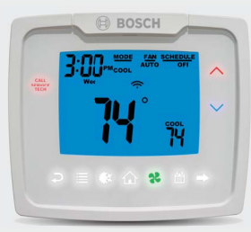
Thermostat Controls
Thermostat features
- 7-Day, 5-2-Day, or 5-1-1- Day Programmable
- Configurable for Multiple Systems
- Large Display with Backlight
- Selectable Fahrenheit or Celsius
- Icon Indicator Lights
- Relay Outputs – Minimum Voltage Drop in Thermostat
- Ideally Suited for:
- — Residential (New Construction/Replacement)
- — Light Commercial
- Service Alarm
- Fault Detection and History
Package contents/tools required
Package includes:
- Thermostat, base
- Wiring labels
- Screws and wall anchors
- 2 “AA” Alkaline batteries
- Installation, Operation and Application Manual
Tools required for installation:
- Drill with 3/16” bit,
- Hammer
- Screwdriver
Specifications
| Description | Value |
| Electrical Rating: | 24 VAC (18-30 VAC), 1 amp maximum per output terminal, 5 amp maximum total load |
| DC Power: | 3.0 VDC (2 “AA”Alkaline batteries) |
| Temperature Control Range: | 45°F to 90°F (7°C to 32°C) Accuracy: ±1°F (±0.5°C) |
| Anti-short Cycle | 4 minutes (bypass anti-short cycle delay by returning to OFF mode and pressing the home icon). |
| Backlight Operations: | 15 seconds |
Spare parts
| Spare part description | Bosch Part Number |
| Backplate (Baseplate) | 8-733-945-500 |
Installation
Removing existing thermostat
DANGER: ELECTRICAL SHOCK HAZARD
Turn off power at the main service panel by removing the fuse or switching the appropriate circuit breaker to OFF position before removing the existing thermostat.
- Turn off power to heating and cooling system by removing the fuse or switching the appropriate circuit breaker off .
- Remove cover of old thermostat; this should expose the wires.
- Label the existing wires with the enclosed wire labels before removing wires.
- After labeling wires, remove wires from wire terminals.
- Remove existing thermostat base from wall.
- Refer to the following section for instructions on how to install this thermostat.
Battery installation and information
Two “AA” alkaline batteries are used for backup power only. They are installed into the back of the thermostat. Orient them in the correct direction as shown on the plastic thermostat case.
The batteries should be changed yearly to prevent leakage from damaging the thermostat and voiding your warranty.
If the batteries are not changed or low and the thermostat is not connected to 24 VAC or loses 24 VAC power, the thermostat will eventually display and conserve
energy by maintaining a lower setpoint in heating and a higher setpoint in cooling.
Installing thermostat
DANGER: ELECTRICAL SHOCK HAZARD
Turn off power at the main service panel by removing the fuse or switching the appropriate circuit breaker to OFF position before removing the existing thermostat.
CAUTION: Thermostat installation must conform to local and national building and electrical codes and ordinances.
Mount the thermostat about five feet above the floor. Do not mount the thermostat on an outside wall, in direct sunlight, behind a door, or in an area affected by a vent or duct.
- Turn off power to heating & cooling system by removing the fuse or switching the appropriate circuit breaker off .
- To remove sub base, pull it from the thermostat.
- Put thermostat sub base against the wall where you plan to mount it (be sure wires will feed through the wire opening in the sub base of the thermostat).
- Mark the placement of the mounting holes.
- Set thermostat sub base and thermostat away from working area.
- Using a 3/16” drill bit, drill holes in the places you have marked for mounting.
- Use a hammer to tap supplied anchors in mounting holes.
- Insert stripped, labeled wires in matching wire terminals. Tighten screws to secure wires.
CAUTION: Be sure exposed portion of wires does not touch other wires.
- Gently tug wire to be sure of proper connection. Double check that each wire is connected to the proper terminal.
- Install 2 “AA” batteries into back of thermostat.
- Snap thermostat onto the sub base.
- Turn on power to the system at the main service panel.
- Configure thermostat to match the type of system you have.
- Test thermostat operation as described in “Testing the Thermostat”.
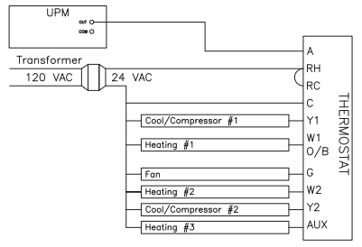
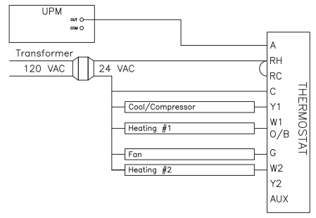
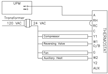
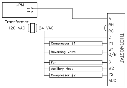
Wiring diagrams
Factory installed jumper between RH and RC is required. Thermostat is powered between RH & C.
Terminal designator descriptions
- A – Alarm/display (24 VAC input, switched from RH)
- RC, RH – 24 VAC hot
- C – 24 VAC common
- Y1 – 1st stage cool, 1st stage heat for heat pumps
- Y2 – 2nd stage cool for 2-stage or 2-compressor systems. 2nd stage heat for 2-stage or 2-compressor heat pump systems.
- G – Fan
- W1/O/B – Configurable
- W1 – 1st stage heat for non-heat pump systems
- O – Cool active reversing valve
- B – Heat active reversing valve
- W2 – 2nd stage heat for 1 compressor heat pump and non-heat pump
- AUX – 3rd stage heat
Conventional System (Dual Compressor) 3H2C
Conventional System (Dual Compressor) 2H2C
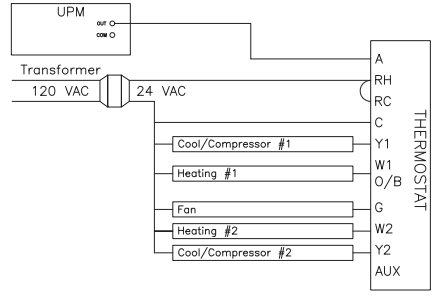
Conventional System (Single Compressor) 2H1C
Heat Pump System (Single Compressor) 2H1C
Heat Pump System (Dual Compressor) 3H2C
System setup and configuration
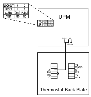
Connection to the UPM
The UPM’s ALARM COM terminal should be connected to R on the UPM board (refer to unit manual for more information), and the ALARM OUT terminal should
be connected to the A terminal on the thermostat.
Configuration of the UPM
The ALARM DIP switch on the UPM has to be set to the ON position (“PULSE”). Simply push the right side of this switch, so it is down on the right side and up on the left side.
Output chart
| Description | 1st Cool | 2nd Cool | 1st Heat | 2nd Heat | 3rd Heat |
| Heat/Cool | Y1, G | YI, G | W1, G* | W1, W2, G* | W1, W2, AUX, G* |
| Heat Pump (one compressor, single stage ) | Y1, G, O | Y1, G, O | Y1, G, B | Y1, W2,G, B | Y1, W2,AUX, G, B |
| Heat Pump (one compressor, two stage and two compressor.) | Y1, G, O | Y1, Y2, G, O | Y1, G, B | Y1, Y2, G, B | Y1, Y2, W2,G, B |
| Emergency Heat (heat pump only) | N/A | N/A | W2, G | W2, AUX**,G | N/A |
- G not on for gas/oil systems
* One compressor only
The thermostat is configurable for all systems. The configuration directly affects the outputs. Use the output chart to correctly configure and wire the thermostat to your system.
Configuration and thermostat lock
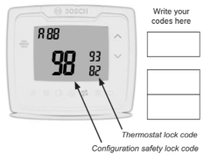
During Configuration Mode, certain settings are protected by a numeric code access screen to prevent unintentional changes that could potentially damage the system or create a dangerous condition.
Whenever changes are attempted to one of the critical settings, the unlock code screen will appear:

The unlock code for these critical settings can be found during the power-up sequence.
The large number (indicated by “98” in the diagram) is the code that will unlock the desired configuration setting. The smaller numbers (indicated by “93” and
“82” in the diagram) are codes used to lock and unlock your thermostat to prevent tampering.
To view the default codes for your thermostat, remove the thermostat from the sub base and, if using batteries, remove one battery for 10 seconds. Replacing the batteries or reinstalling thermostat will cause the codes to display for approximately 5 seconds.
Locking & unlocking thermostat
Changing the lock code
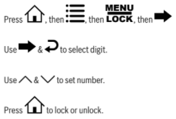
To change the lock code, do the following:
- Press home key , then press menu key until Lock menu displays.
- Enter the current lock codes. To fi nd the current lock codes, follow the instructions under “Configuration and Thermostat Lock”.
- Press to enter new lock codes.
- Enter new lock codes.
- Press home key . The Lock Codes have been updated.
Upon subsequent power ups, new lock codes will display.
Configuration mode
The configuration mode is used to set the thermostat to match your heating/cooling system. The thermostat functions with heat pump, air conditioning, gas, oil, or electric heat systems. To configure the thermostat, perform the following steps:
- Press home , then press menu repeatedly until menu config is selected.
2. Press to advance from one screen to the next.

Pressing will return you to the previous screen.

- Press the up or down to change settings within each screen. Changes are saved automatically.
- To exit configuration mode, press . Auto exit occurs after two minutes with no icons touched.
Configuration Mode Settings
The setup screens for Configuration Mode are as follows:
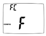
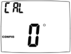
Temperature Scale (F or C)
— Set the number of degrees between your “setpoint” temperature and your “turn on” temperature.
— Press the up or down key to set differential value.
— Press to advance to the next screen.
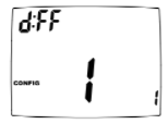
1st Stage Temperature Differential (1°F to 5°F) (0.5°C to 2.5°C)
— Set the number of degrees between your “setpoint” temperature and your “turn on” temperature.
— Press the up or down to set differential value.
— Press to advance to the next screen.

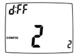
2nd Stage Temperature Differential (1°F to 5°F) (0.5°C to 2.5°C)
— Set the number of degrees between when stage 1 turns on and when stage 2 turns on.
— Press the up or down to set differential value.
— Press to advance to the next screen.
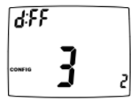
3rd Stage Temperature Differential (1°F to 5°F) (0.5°C to 2.5°C)
— Set the number of degrees between when stage 1 turns on and when stage 2 turns on.
— Press the up or down to set differential value.
— Press to advance to the next screen.
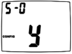
Staged Off Outputs
— Select whether the outputs for heating and cooling are staged off independently or are satisfied simultaneously.
— no Outputs off simultaneously (best for dual fuel). y Outputs staged off independently.
For 2 compressor heat pumps and multi-stage gas/oil systems, stage 3 is staged off independently when SO is set to no
— Press the up or down to set.
— Press to advance to the next screen.
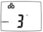
Minimum Dead band (1°F to 9°F) (1°C to 5°C)
— Set the minimum separation between heat setpoint and cool setpoint in Auto Changeover Mode.
— Press the up or down to set dead band value.
— Press to advance to the next screen.
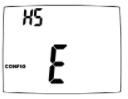
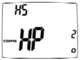
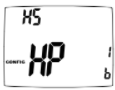
Heat Source: There are six heat source settings:
WARNING: Incorrect settings can damage system and/or cause potentially dangerous conditions. Use the code described in Configuration and Thermostat Lock.
Non-Heat Pump
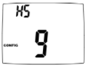
Heat Pump
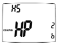
2 stage or 2 compressors
and Heat Active
Reversing Valve
2 stage or 2 compressors
and Cool Active
Reversing Valve
1 compressor single stage
and Heat Active
Reversing Valve
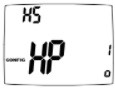
1 compressor single stage
and Cool Active
Reversing Valve
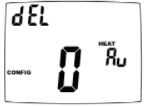
Auxiliary Delay ON (0-60 minutes)
— Set the delay time in minutes for auxiliary heat to be locked out after a call for second stage. This extra savings feature is used to temporarily lock out auxiliary heat devices, allowing just heat pump to try to satisfy heat call.
— Press the up or down to select. Press to advance to the next screen.
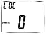
Lockout (0-8°, SLEEP, COOL-HEAT)
— Select the number of degrees set temperature can be changed during keypad lockout. SLEEP setting locks thermostat only during the sleep period to prevent after hours tampering.
COOL-HEAT lockout allows adjustment of the set temperatures to the maximum heat set temperature selected and minimum cool set temperature selected.
The mode cannot be changed while the thermostat is locked.
Press the up or down to select. Press to advance to the next screen.
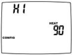
Maximum Heat Setpoint (45°F to 90°F) (7°C to 32°C)
— Adjust to control the maximum heat set temperature allowed.
— Press the up or down to select. Press to advance to the next screen.
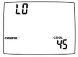
Minimum Cool Setpoint (45°F to 90°F) (7°C to 32°C)
— Adjust to control the minimum cool set temperature allowed.
— Press the up or down to select. Press to advance to the next screen.
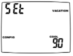
Vacation Cooling Setpoint
— These work in conjunction with the Schedule mode where you set the date and time of your RETURN from vacation.
— Until that date/time, system will remain at the cooling setpoint specified here.
— Press the up or down to select. Press to advance to the next screen.
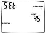
Vacation Heating Setpoint
— These work in conjunction with the Schedule mode where you set the date and time of your RETURN from vacation.
— Until that date/time, system will remain at the heating setpoint specified here.
— Press the up or down key to select. Press to advance to the next screen.
Room Temperature Offset (+9°F to -9°F) (+4.5°C to -4.5°C)
— Adjust to calibrate displayed room temperature to match actual room temperature.
— Press the up or down key to select. Press to advance to the next screen.
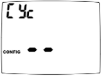
Maximum Cycles Allowed Per Hour (- -, 2-6)

— Press the up or down to select. Press to advance to the next screen.
Hourly Cycle Fan Operation (1-30 minutes per hour)
— Used in conjunction with the Fan HOURLY mode. When the user selects this option, the fan will turn on at the beginning of every hour and run for the number of minutes indicated here.
— Press or to select.
— Press to advance to the next screen.
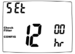
Check Filter Timer (800-2500 hours)
— After the number of (fan running) hours specified, (for example, 1200 hours), the words “CHECK FILTER” will display to remind you to check/change the system filter. The next configuration screen is where the elapsed number of run hours can be reset.
— Press up or down to select.
— Press to advance to the next screen.

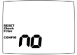
Reset Check Filter Timer
— Used to reset the elapsed number of (fan running) hours for the Check Filter Timer
— Press up or down to select y (YES).
— Press to advance to the next screen or press home key to exit configuration setting mode.
Auto exit occurs after two minutes of no icons being touched.
Mode of operation
BC7801 is based on the i3020R, but adds connections to the UPM to read UPM fault codes. It saves fault code history and displays a new message on the front panel of the thermostat to alert the user to call a service technician to service the system.
The thermostat is a programmable, manual or auto changeover, up to 3-stage heat and up to 2-stage cool thermostat. It functions with air conditioning, heat pumps, gas, oil, or electric heat systems. The thermostat activates the heating appliance when the room temperature is below the set heat temperature (by the differential temperature). When the call for heat has been satisfied, the outputs are turned off . With heat pumps, the thermostat will not let the compressor come on for 4 minutes after it turns off to protect your compressor.
When the room temperature is greater than the set cool temperature (by the differential temperature), the cooling device is activated. When the call for cooling
has been satisfied, the outputs are turned off . The thermostat will not let the compressor come on for 4 minutes after it turns off to protect your compressor.
The program schedule can be overridden by changing the set temperature (/\ or\/). This puts the thermostat into a temporary hold. It will automatically return to
the program schedule depending on how the override feature is configured.
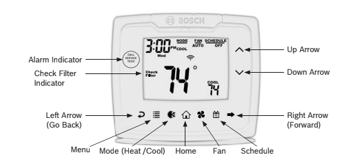
Icon Functions

UP – Used to increase the time, set temperatures, and to adjust configuration settings.

DOWN – Used to decrease the time, set temperatures, and to adjust configuration settings.

MENU – Used to enter configuration, set the clock, lock the thermostat, or select viewing options.
- CONFIG__ Sets up thermostat to work for specific systems.
- CLOCK__ Set year, month, date, and time.
- LOCK__ Allows you to lock the thermostat to prevent tampering.
- VIEW__ Allows you to see both the remote sensor temperatures, date, current schedule period, lock screen, filter accumulated time, and show details (system status).

FAN – Used to select between AUTO, ON, and HOURLY fan operation.

MODE – Used to select between OFF, HEAT, EMERGENCY HEAT (heat pump only), COOL, and AUTO changeover modes.

HOME – Wakes thermostat, returns to home screen, and enters changes into memory.

SCHEDULE – Used to edit program schedule, turn program on and off , and set vacation return dates.

CALL SERVICE TECH – Message appears when the thermostat senses a lockout condition occured on the UPM.

CHECK FILTER – Message appears when the blower motor set runtime has been met. Indicates the air filter should be checked, cleaned, or changed.
Operating Modes
The possible operating modes for the thermostat are: OFF, HEAT, EM HEAT, COOL, and AUTO. Use to select.
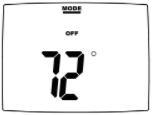
OFF Mode
— In this mode, the thermostat will not turn on the heating or cooling devices
The indoor fan can be turned on manually in every operating mode by pressing until displays. The fan icon appears on the display when the fan operates.
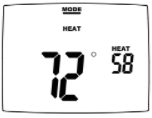
Heat Mode
— In this mode, the thermostat controls the heating system. When the heat outputs, the flame icon appears on the display for each stage of heat that is on.
For heat pumps, there is a four minute delay for your compressor to restart after it has turned off . To bypass the compressor time delay, go to OFF mode and press
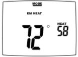
EM Heat Mode
— In this mode, the compressor is bypassed and emergency heat is used.
This mode is only used with heat pumps.
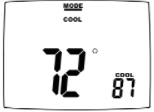
Cool Mode
— In this mode, the thermostat controls the cooling system. When the cooling outputs, the snowflake icon appears on the display for each stage of cool that is on.
There is a four minute delay for your compressor to restart after it has turned off . To bypass the compressor time delay, go to OFF mode and press
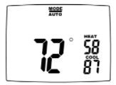
Auto Mode
— In this mode, the thermostat controls both heating and cooling systems simultaneously.
Testing the Thermostat
Once the thermostat is configured, it should be thoroughly tested.
CAUTION: Do not energize the air conditioning system when the outdoor temperature is below 50 degrees. It can result in equipment damage or personal injury.
Heat Test
- Press home , then press mode until heat mode is displayed.
- Adjust the set temperature so it is 5 degrees above the room temperature.
- Heating should come on within a few seconds.
- Adjust the set temperature 2 degrees below the room temperature and the heat should turn off . There may be a fan delay on your system.
For heat pumps, there is a four-minute delay to protect your compressor after it turns off . To bypass the compressor time delay, go to OFF mode and press home.
Cool Test
- Press home , then press mode until cool mode is displayed.
- Adjust set temperature so it is 5 degrees below room temperature.
- Cooling should come on within a few seconds.
- Adjust the set temperature 2 degrees above the room temperature and the cooling should turn off . There may be a fan delay on your system.
There is a four-minute time delay to protect the compressor after it turns off . To bypass the compressor time delay, go to OFF mode and press home.
Fan Test
- Press home , then press fan key icon. displays fan on. Indoor fan turns ON.
- Press home , then press fan key icon. displays fan auto. Indoor fan turns OFF.
Setting the Time and Date
- Press home key , then press menu key until CLOCK is displayed.
- Press to enter date/time setting. Year blinks.

3. Press up or down to select the year.
4. Press to save value and move to month.
5. Press up or down to select the month.
6. Press to save value and move to day.
7. Press up or down to select the day.
8.Press to save value and move to hour.
9. Press up or down to select the hour.
As you move past 12:00, the AM/PM symbol will change automatically.
- Press to save the value and move to minutes.
- Press up or down to select the minutes.
- Press home to exit Time/Date setting.
Setting the program schedule
The thermostat has four periods (WAKE, LEAVE, RETURN, SLEEP) that are customizable for each day of the week. Each period will have a start time, heat
temperature, and cool temperature. The thermostat monitors the day and time, while maintaining the specific conditions you have chosen for each period in your program.
Setting the program schedule:
- Press home , then press schedule until EDIT is displayed.
- Press to enter Program Schedule.
3.The day of the week flashes. Use the up or down to select the day of the week.
You can select the days individually, or if you keep going, there is an option for MON-FRI, MON-SUN or SAT-SUN.
4. Press to continue.
- The period (WAKE, LEAVE, RETURN, SLEEP) begins flashing. Use the up or down to select the desired period.
- Press to continue.
- Hour flashes. Use the up or down to select the hour when you want the current period to begin.
- Press to continue.
- The minutes flash. Use the up or down to select the minutes when you want the current period to begin.
- Press to continue.
- The HEAT temperature flashes. Use the up or down to set the desired heat temperature.
- Press to continue.
- The COOL temperature flashes. Use the up or down to set the desired cool temperature.
- Press to continue.
- Continue to set your entire schedule.
- Press home to exit.
View screen options
- Press home , then press menu repeatedly until the option displays menu view then press .
2. Press to advance to the next screen.
3. Press to go to previous screen.

These screens are visible when the thermostat is locked or unlocked.
View fault Screen
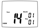
View month, day, and year
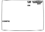
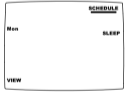
View program schedule settings
— OFF shows when schedule is off.
— SETTINGS show when schedule is on.
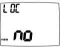
View if locked or unlocked
— no = Unlocked
— y = Locked
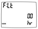
View filter status
— Accumulated fan run time displays.
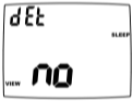
Display setpoints, fan, and program information
— Press up or down to select.
no = Don’t display setpoints and program schedule information.
det = Always display setpoints and program schedule information.
— Press to exit.
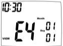
Viewing fault codes
When one of the faults listed below causes a hard lockout on the UPM the unit compressors are disabled and the “Call Service Tech” light is illuminated.
To view UPM’s fault code, go to Menu view. Press multiple times to the last menu item.
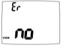
If no fault history is recorded, screen will show “VIEW Er no”.
If fault history is recorded, screen will show “VIEW E{x} {month} {date} {time}” indicating the fault code, date and time of the fault.
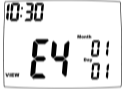
You can press up or down button to browse fault history. The thermostat records the latest 20 faults.
For additional information on fault codes, please refer to the unit instruction and maintenance manual.
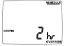
Schedule override
The schedule override feature allows the user to override the program schedule for 1 to 5 hours. In addition, if selected, the schedule can be overridden only until the next transition period.
To access the Schedule override feature, enter the CONFIG screen by pressing the menu button. Then, use to scroll through the menu options until you reach
the SCHEDULE OVERRIDE screen. In the default setting, the Vacation & Schedule periods will be flashing in the upper right corner of the LCD. In this mode, the
Vacation & Schedule will be overridden until the next transition period. To switch to the 1-5 hour override, use the arrow. This mode allows the user to override the Schedule set points for 1-5 hours.
Setting the vacation timer
The vacation timer lets you set the date and time of your RETURN from vacation. Until that date/time, the system will remain at the VACATION heating and cooling setpoints specified in the configuration menu.
To use the EASY VACATION feature:
Press home , then press schedule the to scroll to “Vacation” then press home again. The thermostat will automatically go into Vacation mode with the default return date 1 month later
To set the vacation timer (and begin vacation setpoint mode):
- Press mode to select operating mode.
- Press home , then press schedule until VACATION appears.
- Press to enter the date and time you plan to RETURN from vacation.

4. When your finished entering the date/time, press home.
Factory preprogramming
The thermostat comes pre-programmed with the following schedule:
MONDAY thru SUNDAY
| WAKE | 6:00 AM | LEAVE | 8:00 AM | RETURN | 6:00 PM | SLEEP | 10:00 PM | |||
| HEAT | 70°F | HEAT | 62°F | HEAT | 70°F | HEAT | 62°F | |||
| COOL | 78°F | COOL | 85°F | COOL | 78°F | COOL | 82°F |
Use the following personal program schedule to record your settings:
MONDAY -1
| WAKE | LEAVE | RETURN | SLEEP | |||||||
| HEAT | HEAT | HEAT | HEAT | |||||||
| COOL | COOL | COOL | COOL |
TUESDAY – 2
| WAKE | LEAVE | RETURN | SLEEP | |||||||
| HEAT | HEAT | HEAT | HEAT | |||||||
| COOL | COOL | COOL | COOL |
WEDNESDAY – 3
| WAKE | LEAVE | RETURN | SLEEP | |||||||
| HEAT | HEAT | HEAT | HEAT | |||||||
| COOL | COOL | COOL | COOL |
THURSDAY – 4
| WAKE | LEAVE | RETURN | SLEEP | |||||||
| HEAT | HEAT | HEAT | HEAT | |||||||
| COOL | COOL | COOL | COOL |
FRIDAY – 5
| WAKE | LEAVE | RETURN | SLEEP | |||||||
| HEAT | HEAT | HEAT | HEAT | |||||||
| COOL | COOL | COOL | COOL |
SATURDAY – 6
| WAKE | LEAVE | RETURN | SLEEP | |||||||
| HEAT | HEAT | HEAT | HEAT | |||||||
| COOL | COOL | COOL | COOL |
SUNDAY – 7
| WAKE | LEAVE | RETURN | SLEEP | |||||||
| HEAT | HEAT | HEAT | HEAT | |||||||
| COOL | COOL | COOL | COOL |
Troubleshooting
You can download the PDF version of the Bosch Programmable Thermostat 3H/2C Touch User’s Manual here.