FORWARD
This Whirlpool Service Manual (Part No. W11296289), provides the In-Home Service Professional with service information for the “Whripool®, Maytag®, Amana®, and IKEA® Refrigerators.”
The Wiring Diagram used in this Service Manual is typical and should be used for training purposes only. Always use the Wiring Diagram supplied with the product tech sheet when servicing the refrigerator.
For specific operating and installation information on the model being serviced, refer to the “Use and Care Guide” or “Installation Instructions” provided with the refrigerator.
GOALS AND OBJECTIVES
The goal of this Service Manual is to provide information that will enable the In-Home Service Professional to properly diagnose malfunctions and repair the “Whripool®, Maytag®, Amana®, and IKEA® Refrigerators.”
The objectives of this Service Manual are to:
• Understand and follow proper safety precautions.
• Successfully troubleshoot and diagnose malfunctions.
• Successfully perform necessary repairs.
Section 1: General Information
This section provides general safety, parts, and information for the “Whirlpool®, Maytag®, Amana®, and IKEA® Refrigerators.”
■ Refrigerator Safety
■ Product Specifications
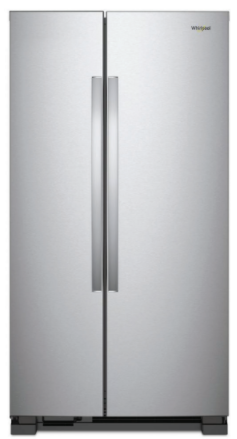
■ Product Feature
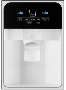
• Control Panel
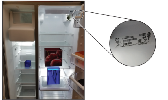
■ Model & Serial Label
• Location
• Model Nomenclature
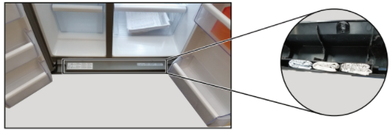
■ Tech Sheet Location
Refrigerator Safety
Your safety and the safety of others are very important.
We have provided many important safety messages in this manual and on your appliance. Always read and obey all safety messages.

This symbol alerts you to potential hazards that can kill or hurt you and others.
All safety messages will follow the safety alert symbol and either the word “DANGER” or “WARNING.”
These words mean:
DANGER: You can be killed or seriously injured if you don’t immediately follow instructions.
WARNING: You can be killed or seriously injured if you don’t follow instructions.
All safety messages will tell you what the potential hazard is, tell you how to reduce the chance of injury, and tell you what can happen if the instructions are not followed.
IMPORTANT SAFETY INSTRUCTIONS
WARNING: To reduce the risk of re, electric shock, or injury when using your refrigerator, follow these basic precautions:
- Plug into a grounded 3 prong outlet.
- Connect to a potable water supply only.
- Do not remove ground prong.
- Do not use an adapter.
- Do not use an extension cord.
- Disconnect power before servicing.
- Replace all parts and panels before operating.
- Remove doors from your old refrigerator
- This appliance is not intended for use by persons (including children) with reduced physical, sensory or mental capabilities, or lack of experience and knowledge, unless they have been given supervision or instruction concerning use of the appliance by a person responsible for their safety.
- Remove doors from your old refrigerator.
- Use nonammable cleaner.
- Keep ammable materials and vapors, such as gasoline, away from refrigerator.
- Use two or more people to move and install refrigerator.
- Disconnect power before installing ice maker (on icemaker kit ready models only).
- Use a sturdy glass when dispensing ice (on some models).
- Do not hit the refrigerator glass doors (on some models).
- Children should be supervised to ensure that they do not play with the appliance.
SAVE THESE INSTRUCTIONS
READ ALSO: Samsung Refrigerator User Manual
Product Specifications
Amana® 36″ Side by Side Refrigerator with Dual Pad External Ice and Water Dispenser
| AHAM Volumes and Shelf Area | |
| Freezer Volume (Cu Ft) | 9.11 |
| Refrigerator Volume (Cu Ft) | 15.46 |
| Total Volume (Cu Ft) | 24.6 |
| Dimensions | |
| Capacity (FT3, Cu Ft) | 24.57 |
| Cabinet Width (IN, inches) | 35 1/2 |
| Cutout Depth (IN, inches) | 27 1/2 |
| Cutout Height (IN, inches) | 69 3/8 |
| Cutout Width (IN, inches) | 36 |
| Depth Closed Excluding Handles (IN, inches) | 31 5/8 |
| Depth Closed Including Handles (IN, inches) | 34 1/8 |
| Depth Excluding Doors (IN, inches) | 28 |
| Depth With Door Open 90 Degree (IN, inches) | 49 3/8 |
| Depth (IN, inches) | 34 5/8 |
| Height to Top of Cabinet (IN, inches) | 68 5/8 |
| Height to Top of Door Hinge (IN, inches) | 69 1 /4 |
| Height (IN, inches) | 69 5/8 |
| Width (IN, inches) | 35 7/8 |
| Description | |
| Type of Refrigerator | Side by Side |
| Details | |
| Advance Foam Insulation | na |
| Cooling Type | Single Evaporator |
| Exterior | |
| Base Grille Color | Black/White |
| Cabinet Color | Black/White |
| Cabinet Finish | Textured |
| Door Color | Black/Stainless Steel/White |
| Door Finish | Smooth |
| Door Style | Contour |
| Door Swing | NA |
| Handle Color | Black/Stainless Steel/White |
| Handle Material | Metal |
| Handle Type | Reach Through Handle |
| Hidden Hinge | Yes |
| Number of Doors | 2 |
| Levelers | 2 Black |
| Wheels | 4-Natural |
| Controls | |
| Automatic Defrost | Yes |
| Location of Controls | Exterior Dispenser |
| Temperature Range | -5/+5 FC 33/45 RC |
| Type of Control | Electronic Touch |
| Water Filter Indicator/Reset | Yes |
| Connected Appliances | No |
| Refrigerator Compartment | |
| Number of Interior Shelves | 4 |
| Conventional Shelves | 1 Fixed Full-Width Glass 3 Adjustable Full-Width Glass |
| Spill-Proof Glass Shelves | No |
| Shelf Supports | Molded |
| Humidity-Controlled Drawers | 1 Full-Width |
| Non-Climate Control Drawers | 1 Full-Width |
| Temperature-Controlled Drawers | No |
| Door Bins | 1 Dairy 1 Fixed Full-Width 3 Adjustable Gallon |
| Supplementary Containers | No |
| Lighting | Incandescent |
| Liner Finish | White Opaque |
| Freezer Compartment | |
| Door Type | Swing |
| Shelves | 3 Fixed Full-Width Wire |
| Freezer Number of Shelves | 3 |
| Freezer Drawer/Basket | 1 Full-Width Lower Plastic |
| Door Bins | 1 Fixed Partial 3 Fixed Full-Width |
| Light | Incandescent |
| Dispenser | |
| Dispenser Type | Exterior Ice and Water |
| Dispenser Options | Filtered Water Measured/Metered Fill |
| Types of Ice | Crushed/Cubed |
| Dispenser Pad Color | Black |
| Icemaker | |
| Icemaker | Factory Installed |
| Icemaker Location | Freezer |
| Electrical | |
| Amps | 7.2 |
| Hz | 60 |
| Volts | 110 |
Whirlpool® 36″ Wide Side by Side Refrigerator – 25 Cu Ft
| AHAM Volumes and Shelf Area | |
| Freezer Volume (Cu Ft) | 9.11 |
| Refrigerator Volume (Cu Ft) | 15.46 |
| Total Volume (Cu Ft) | 24.6 |
| Dimensions | |
| Capacity (FT3, Cu Ft) | 24.57 |
| Depth Closed Excluding Handles (IN, inches) | 31 5/8 |
| Depth Closed Including Handles (IN, inches) | 33 5/8 |
| Depth Excluding Doors (IN, inches) | 28 |
| Depth With Door Open 90 Degree (IN, inches) | 49 5/16 |
| Depth (IN, inches) | 33 5/8 |
| Height to Top of Cabinet (IN, inches) | 68 5/8 |
| Height to Top of Door Hinge (IN, inches) | 69 1 /4 |
| Height (IN, inches) | 69 5/8 |
| Width (IN, inches) | 35 7/8 |
| Description | |
| Type of Refrigerator | Side by Side |
| Details | |
| Advance Foam Insulation | na |
| Cooling Type | Single Evaporator |
| Exterior | |
| Base Grille Color | White/Black/Grey/Biscuit |
| Cabinet Color | White/Black/Grey/Biscuit |
| Cabinet Finish | Textured |
| Door Color | White/Black/Stainless Steel/Sunset Bronze/Fingerprint Resistant Stainless Steel/ Biscuit |
| Door Finish | Smooth |
| Door Style | Contour |
| Door Swing | NA |
| Handle Color | White/Black/Stainless Steel/Biscuit/Fingerprint Resistant Stainless Steel |
| Handle Material | Stainless Steel |
| Handle Type | Reach Through Handle |
| Hidden Hinge | Yes |
| Number of Doors | 2 |
| Controls | |
| Automatic Defrost | Yes |
| Location of Controls | Interior Up Front/Interior/Exterior Dispenser |
| Type of Control | Electronic Touch/Tap Touch |
| Water Filter Indicator/Reset | Yes |
| Connected Appliances | No |
| Refrigerator Compartment | |
| Number of Interior Shelves | 4 |
| Conventional Shelves | 1 Fixed Full-Width Glass 3 Adjustable Full-Width Glass |
| Spill-Proof Glass Shelves | No |
| Shelf Supports | Molded |
| Humidity-Controlled Drawers | 1 Full-Width |
| Non-Climate Control Drawers | 1 Full-Width |
| Temperature-Controlled Drawers | No |
| Door Bins | 1 Dairy 1 Fixed Full-Width 3 Adjustable Gallon |
| Supplementary Containers | No/Can Caddy Bin Utility Compartment |
| Light | LED |
| Freezer Compartment | |
| Door Type | Swing |
| Shelves | 1 Fixed Full-Width Plastic 4 Fixed Full-Width Wire or 3 Fixed Full-Width Glass |
| Freezer Number of Shelves | 3 or 4 or 5 |
| Freezer Drawer/Basket | 1 Full-Width Lower Plastic |
| Door Bins | 4 Fixed Full-Width or 1 Fixed Partial 3 Fixed Full-Width |
| Light | LED |
| Dispenser | |
| Dispenser Type | No Dispenser/Exterior Ice and Water |
| Dispenser Options | Filtered Water Ice Dispenser Lock Night Light |
| Types of Ice | Crushed/Cubed |
| Dispenser Pad Color | Black |
| Icemaker | |
| Icemaker | Optional/Factory Installed |
| Icemaker Kit Part Number | ECKMF95 |
| Icemaker Location | Freezer |
| Electrical | |
| Hz | 60 |
Whirlpool® 33″ Wide Side by Side Refrigerator – 22 Cu Ft
| AHAM Volumes and Shelf Area | |
| Freezer Volume (Cu Ft) | 7.07 |
| Refrigerator Volume (Cu Ft) | 14.65 |
| Total Volume (Cu Ft) | 21.7 |
| Dimensions | |
| Capacity (FT3, Cu Ft) | 21.72 |
| Cabinet Width (IN, inches) | 32 3/4 |
| Depth Closed Excluding Handles (IN, inches) | 31 5/8 |
| Depth Closed Including Handles (IN, inches) | 33 5/8 |
| Depth Excluding Doors (IN, inches) | 28 |
| Depth With Door Open 90 Degree (IN, inches) | 49 5/16 |
| Depth (IN, inches) | 33 5/8 |
| Height to Top of Cabinet (IN, inches) | 65 5/8 |
| Height to Top of Door Hinge (IN, inches) | 66 1 /4 |
| Height (IN, inches) | 66 5/8 |
| Width (IN, inches) | 32 3/4 |
| Description | |
| Type of Refrigerator | Side by Side |
| Details | |
| Advance Foam Insulation | na |
| Cooling Type | Single Evaporator |
| Exterior | |
| Base Grille Color | White/Black/Grey |
| Cabinet Color | White/Black/Grey |
| Cabinet Finish | Textured |
| Door Color | White/Black/Stainless Steel |
| Door Finish | Smooth |
| Door Style | Contour |
| Door Swing | NA |
| Handle Color | White/Black/Stainless Steel |
| Handle Material | Metal |
| Handle Type | Reach Through Handle |
| Hidden Hinge | Yes |
| Number of Doors | 2 |
| Controls | |
| Automatic Defrost | Yes |
| Location of Controls | Interior |
| Type of Control | Electronic Touch |
| Water Filter Indicator/Reset | Yes |
| Connected Appliances | No |
| Refrigerator Compartment | |
| Number of Interior Shelves | 4 |
| Conventional Shelves | 1 Fixed Full-Width Glass 3 Adjustable Full-Width Glass |
| Spill-Proof Glass Shelves | No |
| Shelf Supports | Molded |
| Humidity-Controlled Drawers | 1 Full-Width |
| Non-Climate Control Drawers | 1 Full-Width |
| Temperature-Controlled Drawers | No |
| Door Bins | 1 Dairy 1 Fixed Full-Width 3 Adjustable Gallon |
| Supplementary Containers | No/Can Caddy Bin Utility Compartment |
| Light | LED |
| Liner Finish | White Opaque |
| Freezer Compartment | |
| Door Type | Swing |
| Shelves | 4 Fixed Full-Width Wire |
| Freezer Number of Shelves | 4 |
| Freezer Drawer/Basket | 1 Full-Width Lower Plastic |
| Door Bins | 4 Fixed Full-Width |
| Light | LED |
| Dispenser | |
| Dispenser Type | No Dispenser |
| Icemaker | |
| Icemaker | Optional |
| Icemaker Kit Part Number | ECKMF95 |
| Icemaker Location | Freezer |
| Electrical | |
| Amps | 7.2 |
| Hz | 60 |
| Volts | 110 |
Whirlpool® 33″ Wide Side by Side Refrigerator – 21 Cu Ft
| AHAM Volumes and Shelf Area | |
| Freezer Volume (Cu Ft) | 6.77 |
| Refrigerator Volume (Cu Ft) | 14.65 |
| Total Volume (Cu Ft) | 21.4 |
| Dimensions | |
| Capacity (FT3, Cu Ft) | 21.4 |
| Cabinet Width (IN, inches) | 32 3/4 |
| Depth Closed Excluding Handles (IN, inches) | 31 5/8 |
| Depth Closed Including Handles (IN, inches) | 33 5/8 |
| Depth Excluding Doors (IN, inches) | 28 |
| Depth With Door Open 90 Degree (IN, inches) | 49 5/16 |
| Depth (IN, inches) | 33 5/8 |
| Height to Top of Cabinet (IN, inches) | 65 5/8 |
| Height to Top of Door Hinge (IN, inches) | 66 1 /4 |
| Height (IN, inches) | 66 5/8 |
| Width (IN, inches) | 32 3/4 |
| Description | |
| Type of Refrigerator | Side by Side |
| Details | |
| Advance Foam Insulation | na |
| Cooling Type | Single Evaporator |
| Exterior | |
| Base Grille Color | White/Black/Grey/Biscuit |
| Cabinet Color | White/Black/Grey/Biscuit |
| Cabinet Finish | Textured/Smooth |
| Door Color | White/Black/Stainless Steel/Fingerprint Resistant Stainless Steel/Biscuit |
| Door Finish | Smooth |
| Door Style | Contour |
| Door Swing | NA |
| Handle Color | White/Black/Stainless Steel/Biscuit/Print Resist Stainless Steel |
| Handle Material | Metal |
| Hidden Hinge | Yes |
| Number of Doors | 2 |
| Controls | |
| Automatic Defrost | Yes |
| Location of Controls | Exterior Dispenser/Interior Up Front |
| Temperature Range | -5/+5 FC 33/45 RC |
| Type of Control | Electronic Touch |
| Refrigerator Compartment | |
| Number of Interior Shelves | 4 |
| Conventional Shelves | 1 Fixed Full-Width Glass 3 Adjustable Full-Width Glass |
| Spill-Proof Glass Shelves | No |
| Shelf Supports | Molded |
| Humidity-Controlled Drawers | 1 Full-Width |
| Non-Climate Control Drawers | 1 Full-Width |
| Temperature-Controlled Drawers | No |
| Door Bins | 1 Dairy 1 Fixed Full-Width 3 Adjustable Gallon |
| Supplementary Containers | No/Can Caddy Bin Utility Compartment |
| Light | LED |
| Freezer Compartment | |
| Door Type | Swing |
| Shelves | 3 Adjustable Full-Width Glass or 3 Fixed Full-Width Wire |
| Freezer Number of Shelves | 3 |
| Freezer Drawer/Basket | 1 Full-Width Lower Plastic |
| Door Bins | 3 Fixed Full-Width |
| Light | LED |
| Dispenser | |
| Dispenser Type | Exterior Ice and Water |
| Dispenser Options | Filtered Water Ice Dispenser Lock Measured/Metered Fill Night Light |
| Types of Ice | Crushed/Cubed |
| Icemaker | |
| Icemaker | Factory Installed |
| Icemaker Location | Freezer |
| Electrical | |
| Hz | 60 |
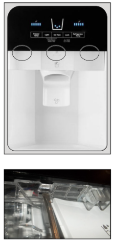
Product Features
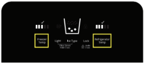
CONTROL PANEL
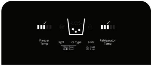
Refrigerator Control:
Press Refrigerator Temp to view the current set point for the refrigerator.
Press Refrigerator Temp again to adjust the set point. The setting will increase by 1 bar with each press of the button, returning to 1 bar after reaching 5 bar.
After 2 minutes of inactivity, any changes will be saved and the display will return to the home screen.
Freezer Control:
Press Freezer Temp to view the current set point for the freezer.
Press Freezer Temp again to adjust the set point. The setting will increase by 1 bar with each press of the button, returning to 1 bar after reaching 5 bar.
After 2 minutes of inactivity, any changes will be saved and the display will return to the home screen.
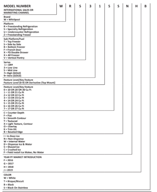
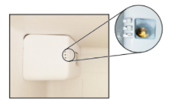
Model & Serial Number Location
Tech Sheet Location
Model Nomenclature
Section 2: Diagnostics
This section provides diagnostic mode and sales mode information for the “Whirlpool®, Maytag®, Amana®, and IKEA® Refrigerators.”
■ Safety
■ Diagnostics Mode
■ Sales Mode
For Service Technician Use Only
Safety
Danger:
Electrical Shock Hazard
Only authorized technicians should perform diagnostic voltage measurements.
After performing voltage measurements, disconnect power before servicing.
Failure to follow these instructions can result in death or electrical shock.
Warning:
Electrical Shock Hazard
Disconnect power before servicing.
Replace all parts and panels before operating.
Failure to do so can result in death or electrical shock.
Voltage Measurement Safety Information
When performing live voltage measurements, you must do the following:
■ Verify the controls are in the off position so that the appliance does not start when energized.
■ Allow enough space to perform the voltage measurements without obstructions.
■ Keep other people a safe distance away from the appliance to prevent potential injury.
■ Always use the proper testing equipment.
■ After voltage measurements, always disconnect power before servicing.
IMPORTANT: Electrostatic Discharge (ESD) Sensitive Electronics
ESD problems are present everywhere. ESD may damage or weaken the electronic control assembly. The new control assembly may appear to work well after repair is finished, but failure may occur at a later date due to ESD stress.
■ Use an antistatic wrist strap. Connect wrist strap to green ground connection point or unpainted metal in the appliance
-OR-
Touch your finger repeatedly to a green ground connection point or unpainted metal in the appliance.
■ Before removing the part from its package, touch the antistatic bag to a green ground connection point or unpainted metal in the appliance.
■ Avoid touching electronic parts or terminal contacts; handle electronic control assembly by edges only.
■ When repackaging failed electronic control assembly in antistatic bag, observe above instructions.
Diagnostics Mode
Service Information
- Compressor suction and process stubs may not be interchanged.
- Refrigerant charge must be applied to high side only.
- Ice maker and water valve not original equipment on all models.
- NOTE: Ice maker cycle must be initiated electrically. Do not try to manually start the cycle.
- Part number can be found on the component.
*Normal operating conditions are viewed when the air and temperature controls are at the mid-sitting freezer section 0 to -5°F and unit is cycling.
NOTE: Watt and pressure readings will vary and are influenced by the existing condition of the appliance such as the iced-up evaporator, condition of the condenser, defrost cycle, pull-down time and customer use.
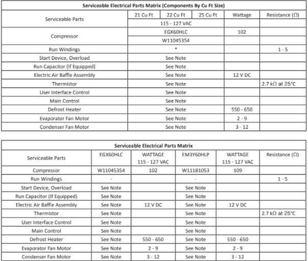
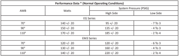
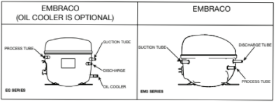
Compressor Options – Refer To Applicable Design
(Oil cooler not present on all compressors)
Service Key Assignment
During the first five minutes after a power on, put setting temperature at the minimum position for both RC and FC.
Afterward, hold “FREEZER TEMP” and “ICE TYPE” keys for 3 seconds to enter service mode.
After entering service mode, all LEDs will turn on to verify all LEDs can turn on.
To proceed to service steps, a user shall press all 5 keys individually from left to right to turn off all LEDs and validate touch function.
NOTE: For smooth operation of user interface key activation, wait at least 1 second between each press, to let the system toggle between service steps.
| KEYS | DESCRIPTION |
| SW2 = Light Key | Increment Key: Advance to next step |
| SW4 = Lock Key | Decrement Key: Go back to the previous step |
| SW5 = RC Temp Key | Change Setting Key: Turn ON/OFF load, PAUSE/RUN specific test |
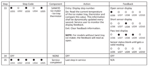
NOTE: For IDI model with twist tray ice maker, upon entry into service, an ice maker is enabled and a homing operation is performed, this is to avoid of any other load interference when SANKYO IM is performing the Homing operation.
The LEDs on the FREEZER TEMP section will show the step number while the LEDs above REFRIGERATION TEMP section will show the feedback. Steps 29 to 35 apply only for models with twist tray maker in the door (IDI).
For Service Technician Use Only
Service Mode Steps For Athena Control
During the first 30 seconds after power up the product, press TEMP setting button, until is located min position, then hold the refrigerator door switch to simulate the door is closed, and at the same time hold press refrigerator TEMP button for 5 seconds until the board enters service mode.
System Action
Into service state mode, all temperature LEDs turn on for and turn OFF after 10 seconds.
A user must use the SW1 button to advance steps into service mode. User shall wait 3 seconds between each keypress to allow the system stabilization.
All sensors will be tested without required action from service personnel. This action is taken after the heater off.
After last step press SW1 to exit service mode, user interface will reset to the last mode and start the power-up state.
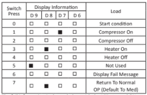
The fail information is shown below with the LEDs turned ON, this will appear in step 6 from the above table.
NOTE: If step 6 shows all LEDs blank means that board drivers and sensors are working correctly.
Display Fail Message State Table
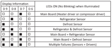
For Display Model Only:
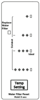
For water filter indicator reset LED test, press and hold TEMP button for 3 seconds until the water filter LED blinks to verify LED function.
For dispenser function, use the wiring diagram for reference to validate all connections and switch operation.
Sales Demo Mode
CUDA 17 IDI & DPLUS
Water Filter Reset & Showroom Mode
| SHOWROOM Mode Use Case | System Feedback | Reference |
| To enter showroom mode 1. Within 2 minutes after power- up, press and hold (RC & FC TEMP keys) for 5 seconds. | The system enters in Showroom mode. UI performs “showroom animation”: • All five LEDs (RC & FC TEMP LEDs) turn on one by one from left to right and then right to left and keep cycling. (Cycling rate: 1 cycle per second). • Showroom mode does not activate sleep mode. • If there is no user action during 2 minutes of showroom mode, the animation will stop and then UI behaves (fake) as normal mode. • During the animation, if the user touches any key, the animation will stop and UI behaves as a fake normal mode. • During fake normal mode, after two minutes without user interaction, the animation will start again to indicate that UI is in showroom mode. | Fake normal mode is normal mode with all cooling loads off. |
| Press (FC TEMP SETTING or RC TEMP SETTING) key in the showroom mode. | The recommended temperature setting (i.e. ) is on. Then UI behaves (fake) as normal mode if the user presses any key again, except that cooling stays off in showroom mode and no temperature setting is saved. | |
| Press (LIGHT) Key in show room | Behavior will be same as normal operation. | |
| Press (ICE TYPE) key in show room mode. | Ice-type LED changes between crush when the user presses the Ice Type key. |
CUDA 17 D Iite & Non Disp
Water Filter Reset & Showroom Mode
| Showroom Mode Use Case | System Feedback |
| To enter showroom mode 1. Within 2 minutes after power-up, toggle (TEMP SETTING) button till is on. 2. Hold DOOR SWITCH to simulate door close. 3. Press and hold (TEMP SETTING) for 3 seconds. | The system enters into Showroom mode. UI performs “showroom mode”: • All four LEDs turns on one by one from top to bottom and then bottom to top and keep cycling. (Cycling rate: 1 cycle per second) |
| Press (TEMP SETTING) button in showroom mode. | LEDs stop cycling. The recommended temperature setting (i.e.) is on. Then UI behaves (fake) as normal mode if user presses (TEMP SETTING) button again, except that cooling stays off in the showroom mode and no temperature setting is saved. |
| User inactivity for 3 seconds | UI returns to “showroom animation”. |
| To exit showroom mode 1. Toggle (TEMP SETTING) button will is on. 2. Hold DOOR SWITCH to simulate door close. 3. Press and hold (TEMP SETTING) for 3 seconds. | UI exits showroom mode and returns to normal mode with the default setting. |
| Power interval during showroom mode. | UI returns to Normal mode after a power reset or power failure. |
Section 3: Component Testing
This section provides the wiring diagram and component location for the “Whirlpool®, Maytag®, Amana®, and IKEA® Refrigerators.”
■ Safety
■ Wiring Diagram
■ Component Location
For Service Technician Use Only
Safety
DANGER
Electrical Shock Hazard
Only authorized technicians should perform diagnostic voltage measurements.
After performing voltage measurements, disconnect power before servicing.
Failure to follow these instructions can result in death or electrical shock.
WARNING
Electrical Shock Hazard
Disconnect power before servicing.
Replace all parts and panels before operating.
Failure to do so can result in death or electrical shock.
Voltage Measurement Safety Information
When performing live voltage measurements, you must do the following:
■ Verify the controls are in the off position so that the appliance does not start when energized.
■ Allow enough space to perform the voltage measurements without obstructions.
■ Keep other people a safe distance away from the appliance to prevent potential injury.
■ Always use the proper testing equipment.
■ After voltage measurements, always disconnect power before servicing.
IMPORTANT: Electrostatic Discharge (ESD) Sensitive Electronics
ESD problems are present everywhere. ESD may damage or weaken the electronic control assembly. The new control assembly may appear to work well after repair is finished, but failure may occur at a later date due to ESD stress.
■ Use an antistatic wrist strap. Connect wrist strap to green ground connection point or unpainted metal in the appliance
-OR-
Touch your finger repeatedly to a green ground connection point or unpainted metal in the appliance.
■ Before removing the part from its package, touch the antistatic bag to a green ground connection point or unpainted metal in the appliance.
■ Avoid touching electronic parts or terminal contacts; handle electronic control assembly by edges only.
■ When repackaging failed electronic control assembly in antistatic bag, observe above instructions.
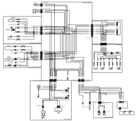
Wiring Diagram
Wiring diagram A for models:
WRS321SDHB, WRS321SDHB01, WRS321SDHB02, WRS321SDHV, WRS321SDHV01, WRS321SDHV02, WRS321SDHW, WRS321SDHW01, WRS321SDHW02, WRS321SDHZ, WRS321SDHZ01, WRS321SDHZ02, WRS325SDHB, WRS325SDHB01, WRS325SDHB02, WRS325SDHV, WRS325SDHV01, WRS325SDHV02, WRS325SDHW, WRS325SDHW01, WRS325SDHW02, WRS325SDHZ, WRS325SDHZ01, WRS321SDHB, WRS321SDHB00, WRS321SDHV, WRS321SDHV00, WRS321SDHW, WRS321SDHW00, WRS321SDHZ, WRS321SDHZ00, WRS325SDHB, WRS325SDHB00, WRS325SDHV, WRS325SDHV00, WRS325SDHW, WRS325SDHW00, WRS325SDHZ, WRS325SDHZ00.
For Service Technician Use Only
Wiring diagram A
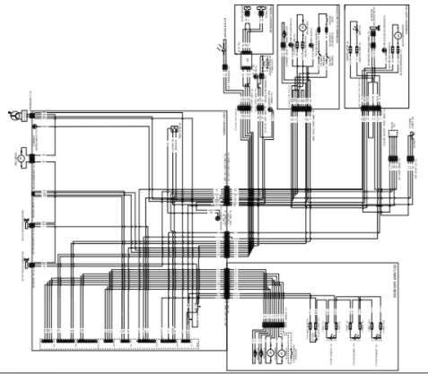
For Service Technician Use Only
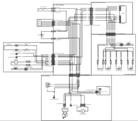
Wiring diagram B for models:
ASI2575GRB, ASI2575GRB01, ASI2575GRS, ASI2575GRS01, ASI2575GRW, ASI2575GRW01, WRS315SDHB, WRS315SDHB01, WRS315SDHM, WRS315SDHM01, WRS315SDHT, WRS315SDHT01, WRS315SDHW, WRS315SDHW01, WRS311SDHB, WRS311SDHB00, WRS311SDHB01, WRS311SDHM, WRS311SDHM00, WRS311SDHM01, WRS311SDHM02, WRS311SDHT, WRS311SDHT00, WRS311SDHT01, WRS311SDHW, WRS311SDHW00, WRS311SDHW01, WRS311SDHZ, WRS311SDHZ00, WRS311SDHZ01, WRS315SDHB, WRS315SDHB00, WRS315SDHM, WRS315SDHM00, WRS315SDHM02, WRS315SDHT, WRS315SDHT00, WRS315SDHW, WRS315SDHW00, WRS315SDHZ, WRS315SDHZ00, WRS315SDHZ01.
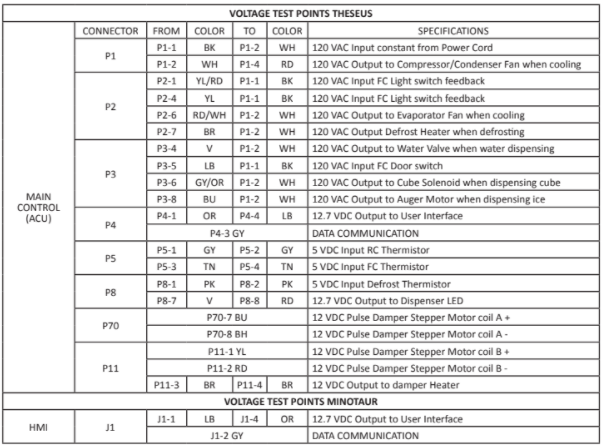
| VOLTAGE TEST POINTS ATHENA | ||||||
| CONNECTOR | FROM | COLOR | TO | COLOR | SPECIFICATIONS | |
| J2 | J2-1 | PK | J2-2 | PK | 5 VDC Input Evaporator Thermistor | |
| J2-3 | GY | J2-4 | GY | 5 VDC Input Refrigerator Thermistor | ||
| MAIN CONTROL (ACU) | JP1 | JP1-1 | YL | JP1-3 | BK | 120 VAC input FC Light switch feedback when the door is open |
| JP1-2 | BR | JP1-6 | WH | 120 VAC Output Defrost Heater when defrosting | ||
| JP1-3 | BK | JP1-6 | WH | 120 VAC Input Constant from Power Cord | ||
| JP1-4 | RD | JP1-6 | WH | 120 VAC Output to Compressor and Fans when cooling |
Wiring diagram C for models:
WRS312SNHB01, WRS312SNHW01, WRS315SNHB, WRS315SNHB01, WRS315SNHM, WRS315SNHM01, WRS315SNHW, WRS315SNHW01, WRSA15SNHN, WRSA15SNHN01, WRSA15SNHZ, WRSA15SNHZ01, WRS312SNHB, WRS312SNHB00, WRS312SNHM, WRS312SNHM00, WRS312SNHM01, WRS312SNHW, WRS312SNHW00, WRS315SNHB, WRS315SNHB00, WRS315SNHM, WRS315SNHM00, WRS315SNHW, WRS315SNHW00, WRSA15SNHN, WRSA15SNHN00, WRSA15SNHZ, WRSA15SNHZ00.
| VOLTAGE TEST POINTS ATHENA | ||||||
| CONNECTOR | FROM | COLOR | TO | COLOR | SPECIFICATIONS | |
| J2 | J2-1 | PK | J2-2 | PK | 5 VDC Input Evaporator Thermistor | |
| MAIN CONTROL (ACU) | J2-3 | GY | J2-4 | GY | 5 VDC Input Refrigerator Thermistor | |
| JP1 | JP1-1 | YL | JP1-3 | BK | 120 VAC Input FC Light switch feedback when the door is open | |
| JP1-2 | BR | JP1-6 | WH | 120 VAC Output Defrost Heater when defrosting | ||
| JP1-3 | BK | JP1-6 | WH | 120 VAC Input constant from Power Cord | ||
| JP1-4 | RD | JP1-6 | WH | 120 VAC Output to Compressor and Fans when cooling |
Component Location
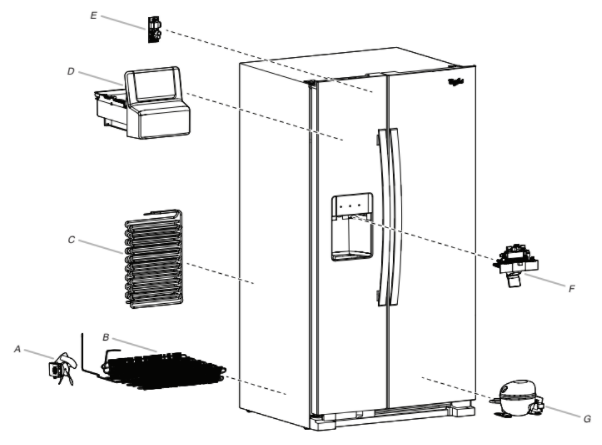
A. Condenser Fan
B. Condenser
C. Freezer Evaporator
D. Auger Ice Dispenser
E. Athena Control Board
F. Front Door Dispenser Unit
G. Compressor
Section 4: Component Access
This section provides service parts access, removal, and replacement instructions for the “Whirlpool®, Maytag®, Amana®, and IKEA® Refrigerators.”
- Removing the front wheel
- Accessing the interior of the unit
- Removing the damper
- Removing the freezer shelf
- Removing the dispenser
- Accessing the freezer evaporator and components
- Accessing the dispenser area (removing UI)
- Accessing the machine compartment
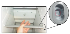
Removing the Front Wheel
Warning:
- Electrical Shock Hazard
Disconnect power before servicing. - Replace all parts and panels before operating.
- Failure to do so can result in death or electrical shock.
- Below picture shows level screw location.
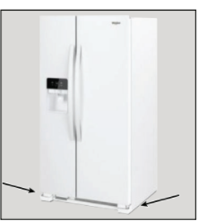
- Below picture shows level screw.
A. Level screw
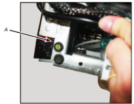
- Below picture shows the clip and pin.
A. Clip and pin
- Remove the leveling screw and pry up the clip and remove.
Then remove the pin at this point you can remove the wheel assembly.
5. Below picture shows the wheel out of the unit.
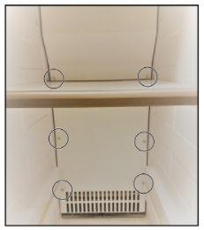
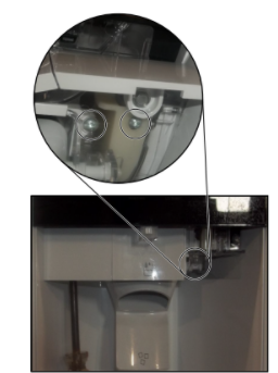
Accessing Interior of Unit
WARNING
Electrical Shock Hazard
Disconnect power before servicing.
Replace all parts and panels before operating.
Failure to do so can result in death or electrical shock.
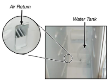
- Below picture shows the interior of the unit.
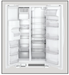
- There are some changes to the Cuda 17 compared to older Standard side by side refrigerator.
• The return air was moved from the center of fresh food to lower left corner and it goes straight through.
• The controls are all on the dispenser.
Removing the Damper
WARNING
- Electrical Shock
- Disconnect power before servicing.
- Replace all parts and panels before operating.
- Failure to do so can result in death or electrical shock.
- To remove damper completely first remove upper air duct in Freezer. You will have to remove IM and bin. Then remove the screw at the top of the air duct and it will come off.
- Once freezer cover gets off then push on the tabs in the air supply area and this will push the damper out.
- Air damper is motor driven. To get to the damper first remove the screw in housing.
- The cover will come off and then you can access the wiring harness.
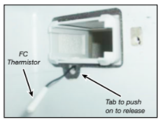
- The damper will come out. The damper has both RC and FC thermistor on the harness.
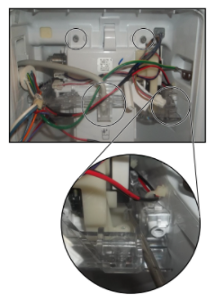
6. Below picture shows connections for fresh food door.
Removing the Freezer Shelf
WARNING:
Electrical Shock Hazard
Disconnect power before servicing.
Replace all parts and panels before operating.
Failure to do so can result in death or electrical shock.
- Pick up the right side of the shelf and slide to the right as you would normally do. The bar will go into the deep pocket of the shelf holder.
- Now, take a needle nose pliers or you can try your fingers and grab the bar on the LEFT and push the bar over to the right until the end is exposed. Do this for both front and back.
Note: At this point, the shelf can be dropped down and removed. To put the shelf back in just reverse the process.
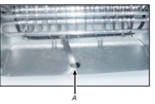
Accessing the Freezer Evaporator and Components
WARNING
Electrical Shock Hazard
Disconnect power before servicing.
Replace all parts and panels before operating.
Failure to do so can result in death or electrical shock.
- After removing the shelves, remove the six 1/4″ (6.4 mm) hex head screws, lift up on the panel and pull forward to remove.
- You will now have access to the Evaporator, Defrost heater, Defrost thermistor, Defrost drain pan, and Evaporator fan assembly.
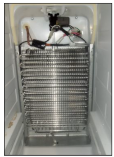
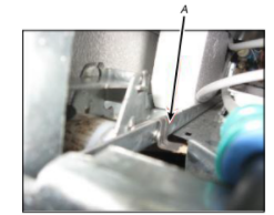
- Below picture shows freezer components. Defrost thermistor goes on the cap tube side.
- The unit does have heat probe in defrost drain. This transfers the heat from the defrost heater to the drain to prevent ice build up and causing drain restrictions.
A. Heat Probe
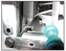
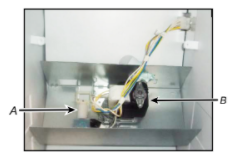
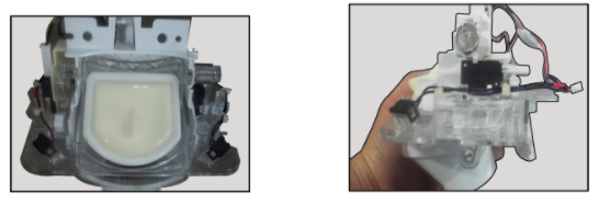
- Below picture shows auger motor and cube/crushed coil.
A. Auger Solenoid
B. Auger Drive Motor
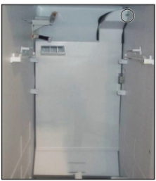
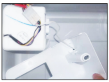
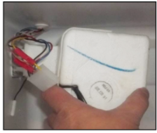
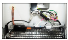
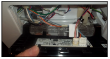
Accessing the Dispenser Area (Removing UI)
WARNING
Electrical Shock Hazard
Disconnect power before servicing.
Replace all parts and panels before operating.
Failure to do so can result in death or electrical shock.
- Below picture shows the dispenser area.
2. Once sides are removed then use a screwdriver to push on all three tabs that are behind UI to release it .
- Remove the left side covers by removing screws to access the dispenser.
4. You now have access to the wiring for UI.
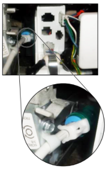
- To remove the water line push the locking tab out. Do this from the bottom.
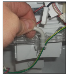
- To remove ice door, remove water line for the holder. Remove the upper screws then pry tabs.
7. Below pictures show the ice chute assembly.
READ ALSO: Montgomery Ward 7.4 cu. ft. Refrigerator-Freezer Instruction Manual (MODEL: FR75W, FR75B)
Accessing the Machine Compartment
Warning:
Electrical Shock Hazard
Disconnect power before servicing.
Replace all parts and panels before operating.
Failure to do so can result in death or electrical shock.
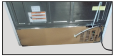
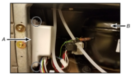
- Below picture shows the machine compartment. Remove screws from the back panel.
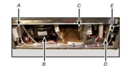
- You now have access to the following components:
A. Compressor inverter
B. Compressor
C. Condenser Fan Motor
D. Filter Dryer
E. Dual water valve
- To remove the compressor inverter, remove the two 1/4″
(6.4 mm) hex head screws. Disconnect the wiring then pull
the inverter out.
A. Compressor inverter
B. Compressor
- To remove the condenser fan, remove the two 1/4″ (6.4 mm) hex head screws, disconnect the wiring and lift out.
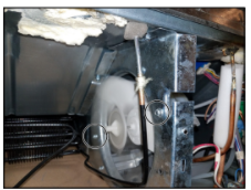
- To remove the Dual Water Valve, remove the two 1/4″ (6.4 mm) hex head screws, disconnect the wiring and water lines then lift out.
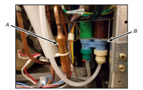
A. Filter Dryer
B. Dual water valve
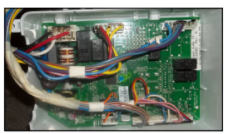
6. Below picture shows high voltage board.
PRODUCT SPECIFICATIONS &WARRANTY
INFORMATION SOURCES
IN THE UNITED STATES:
FOR PRODUCT SPECIFICATIONS AND WARRANTY INFORMATION CALL:
FOR WHIRLPOOL PRODUCTS: 1-800-253-1301
FOR TECHNICAL ASSISTANCE WHILE AT THE CUSTOMER’S HOME CALL:
THE TECHNICAL ASSISTANCE LINE: 1-800-832-7174
HAVE YOUR STORE NUMBER READY TO IDENTIFY YOU AS AN AUTHORIZED IN-HOME SERVICE PROFESSIONAL
FOR LITERATURE ORDERS (CUSTOMER EXPERIENCE CENTER):
PHONE: 1-800-851-4605
FOR TECHNICAL INFORMATION AND SERVICE POINTERS:
www.servicematters.com
IN CANADA:
FOR PRODUCT SPECIFICATIONS AND WARRANTY INFORMATION CALL
1-800-461-5681
FOR TECHNICAL ASSISTANCE WHILE AT THE CUSTOMER’S HOME CALL:
THE TECHNICAL ASSISTANCE LINE: 1-800-488-4791 HAVE YOUR STORE NUMBER READY TO IDENTIFY YOU AS AN AUTHORIZED IN-HOME SERVICE PROFESSIONAL
You can download PDF version of Whirlpool Service Manual (Whirlpool®, Maytag®, Amana®, & IKEA® Refrigerators here.