
JOB SPECIFICATION SHEET
Job Number: __________________________________
Model Number:________________________________
Water Hardness: ______________________ ppm or gpg
Capacity Per Unit:______________________________
Mineral Tank Size: Diameter: ___Height:__
Salt Setting per Regeneration:____________________
- Type of Timer:
A. Time Clock
B. Meter Initiated - Downflow: Upflow Upflow Variable
- Meter Size:
A. 3/4-inch Turbine
B. 3/4-inch Paddle Wheel
C. Electronic Pulse Count Meter Size _ - System Type:
A. System #4: 1 Tank, 1 Meter, Immediate, or
Delayed Regeneration
B. System #4: Time Clock - Timer Program Settings:
A. Backwash:__________________ Minutes
B. Brine and Slow Rinse:_________ Minutes
C. Rapid Rinse: ________________ Minutes
D. Brine Tank Refill: ____________ Minutes
E. Pause Time: ________________ Minutes
F. Second Backwash: ___________ Minutes - Drain Line Flow Control: gpm
- Brine Line Flow Controller: gpm
- Injector Size#:
CALIFORNIA PROPOSITION 65 WARNING
WARNING: This product contains chemicals known to the State of California to cause cancer or birth defects or other reproductive harm.
INSTALLATION
Water Pressure
A minimum of 20 pounds (1.4 bar) of water pressure is required for regeneration valve to operate effectively.
Electrical Facilities
An uninterrupted alternating current (A/C) supply is required.
NOTE: Other voltages are available. Please make sure your voltage supply is compatible with your unit before installation.
Existing Plumbing
Condition of existing plumbing should be free from lime and iron buildup. Piping that is built up heavily with lime and/ or iron should be replaced. If piping is clogged with iron, a separate iron filter unit should be installed ahead of the water softener.
Location Of Softener And Drain
The softener should be located close to a drain to prevent air breaks and back flow.
Bypass Valves
Always provide for the installation of a bypass valve if unit is not equipped with one.
CAUTION Water pressure is not to exceed 125 psi (8.6 bar), water temperature is not to exceed 110°F (43°C), and the unit cannot be subjected to freezing conditions.
Installation Instructions
- Place the softener tank where you want to install the unit making sure the unit is level and on a firm base.
- During cold weather, the installer should warm the valve to room temperature before operating.
- All plumbing should be done in accordance with local plumbing codes. The pipe size for residential drain line should be a minimum of 1/2 inch (13 mm). Backwash flow rates in excess of 7 gpm (26.5 Lpm) or length in excess of 20 feet (6 m) require 3/4 inch (19 mm) drain line. Commercial drain lines should be the same size as the drain line flow control.
- Refer to the dimensional drawing for cutting height of the distributor tube. If there is no dimensional drawing, cut the distributor tube flush with the top of the tank.
- Lubricate the distributor o-ring seal and tank o-ring seal. Place the main control valve on tank.
NOTE: Only use silicone lubricant.
- Solder joints near the drain must be done prior to connecting the Drain Line Flow Control fitting (DLFC). Leave at least 6 inches (15 cm) between the DLFC and solder joints when soldering pipes that are connected on the DLFC. Failure to do this could cause interior damage to the DLFC.
- Plumber tape is the only sealant to be used on the drain fitting. The drain from twin tank units may be run through a common line.
- Make sure that the floor is clean beneath the salt storage tank and that it is level.
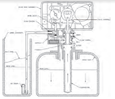
- Place approximately 1 inch (25 mm) of water above the grid plate. If a grid is not utilized, fill to the top of the air check (Figure 1) in the salt tank. Do not add salt to the brine tank at this time.
- On units with a by-pass, place in bypass position. Turn on the main water supply. Open a cold soft water tap nearby and let run a few minutes or until the system is free from foreign material (usually solder) that may have resulted from the installation. Once clean, close the water tap.
- Slowly place the by-pass in service position and let water flow into the mineral tank. When water flow stops, slowly open a cold water tap nearby and let run until the air is purged from the unit.
- Plug unit into an electrical outlet.
NOTE: All electrical connections must be connected according to local codes. Be certain the outlet is uninterrupted.
READ ALSO: Culligan® High Efficiency Automatic Water Softener User’s Manual
START-UP INSTRUCTIONS
The water softener should be installed with the inlet, outlet, and drain connections made in accordance with the manufacturer’s recommendations, and to meet applicable plumbing codes.
- Turn the manual regeneration knob slowly in a clockwise direction until the program micro switch lifts on top of the first set of pins. Allow the drive motor to move the piston to the first regeneration step and stop. Each time the program switch position changes, the valve will advance to the next regeneration step. Always allow the motor to stop before moving to the next set of pins or spaces.
NOTE: For electronic valves, please refer to the manual regeneration part of the timer operation section. If the valve came with a separate electronic timer service manual, refer to the timer operation section of the electronic timer service manual.
- Position the valve to backwash. Ensure the drain line flow remains steady for 10 minutes or until the water runs clear (see above).
- Position the valve to the brine / slow rinse position. Ensure the unit is drawing water from the brine tank (this step may need to be repeated).
- Position the valve to the rapid rinse position. Check the drain line flow, and run for 5 minutes or until the water runs clear.
- Position the valve to the start of the brine tank fill cycle. Ensure water goes into the brine tank at the desired rate. The brine valve drive cam will hold the valve in this position to fill the brine tank for the first regeneration.
- Replace control box cover.
- Put salt in the brine tank.
NOTE: Do not use granulated or rock salt.
TIMER FEATURES
Features of the SXT:
• Power backup that continues to keep time and the passage of days for a minimum of 48 hours in the event of power failure. During a power outage, the control goes into a power-saving mode. It does not monitor water usage during a power failure, but it does store
the volume remaining at the time of power failure.
• Settings for both valve (basic system) and control type (method used to trigger a regeneration).
• Day-of-the-Week controls.
• While in service, the display alternates between time of day, volume remaining or days to regeneration, and tank in service (twin tank systems only).
• The Flow Indicator flashes when outlet flow is detected.
• The Service Icon flashes if a regeneration cycle has been queued.
• A Regeneration can be triggered immediately by pressing the Extra Cycle button for five seconds.
• The Parameter Display displays the current Cycle Step (BW, BF, RR, etc) during regeneration, and the data display counts down the time remaining for that cycle step. While the valve is transferring to a new cycle step, the display will flash. The parameter display will identify the destination cycle step (BW, BF, RR, etc) and the data display will read “—-”. Once the valve reaches the cycle step, the display will stop flashing and the data display will change to the time remaining. During regeneration, the user can force the control to advance to the next cycle step immediately by pressing the extra cycle button.
Setting the Time of Day
- Press and hold either the Up or Down buttons until the programming icon replaces the service icon and the parameter display reads TD.
- Adjust the displayed time with the Up and Down buttons.
- When the desired time is set, press the Extra Cycle button to resume normal operation. The unit will also return to normal operation after 5 seconds if no buttons are pressed.
Queueing a Regeneration
- Press the Extra Cycle button. The service icon will flash to indicate that a regeneration is queued.
- To cancel a queued regeneration, press the Extra Cycle button.
Regenerating Immediately
Press and hold the Extra Cycle button for five seconds.
TIMER OPERATION
Meter Immediate Control
A meter immediate control measures water usage and regenerates the system as soon as the calculated system capacity is depleted. The control calculates the system capacity by dividing the unit capacity (typically expressed in grains/unit volume) by the feed water hardness and subtracting the reserve. Meter Immediate systems generally do not use a reserve volume. However, in twin tank systems with soft-water regeneration, the reserve capacity should be set to the volume of water used during regeneration to prevent hard water break-through. A Meter Immediate control will also start a regeneration cycle at the programmed regeneration time if a number of days equal
to the regeneration day override pass before water usage depletes the calculated system capacity.
Meter Delayed Control
A Meter Delayed Control measures water usage and regenerates the system at the programmed regeneration time after the calculated system capacity is depleted. As with Meter Immediate systems, the control calculates the system capacity by dividing the unit capacity by the feed water hardness and subtracting the reserve. The reserve should be set to insure that the system delivers treated water between
the time the system capacity is depleted and the actual regeneration time. A Meter Delayed control will also start a regeneration cycle at the programmed regeneration time if a number of days equal to the regeneration day override pass before water usage depletes the calculated system capacity.
Time Clock Delayed Control
A Time Clock Delayed Control regenerates the system on a timed interval. The control will initiate a regeneration cycle at the programmed regeneration time when the number of days since the last regeneration equals the regeneration day override value.
Day of the Week Control
This control regenerates the system on a weekly schedule. The schedule is defined in Master Programming by setting each day to either “off” or “on.” The control will initiates a regeneration cycle on days that have been set to “on” at the specified regeneration time.
Control Operation During Regeneration
During regeneration, the control displays a special regeneration display. In this display, the control shows the current regeneration step number the valve is advancing to, or has reached, and the time remaining in that step. The step number that displays flashes until the valve completes driving to this regeneration step position. Once all regeneration steps are complete the valve returns to service and resumes
normal operation.
Pressing the Extra Cycle button during a regeneration cycle immediately advances the valve to the next cycle step position and resumes normal step timing.
Control Operation During Programming
The control only enters the Program Mode with the valve in service. While in the Program Mode, the control continues to operate normally monitoring water usage and keeping all displays up to date. Control programming is stored in memory permanently, eliminating the need for battery backup power.
Manually Initiating a Regeneration
- When timer is in service, press the Extra Cycle button for 5 seconds on the main screen.
- The timer advances to Regeneration Cycle Step #1 (rapid rinse), and begins programmed time count down.
- Press the Extra Cycle button once to advance valve to Regeneration Cycle Step #2 (backwash).
- Press the Extra Cycle button once to advance valve to Regeneration Cycle Step #3 (brine draw & slow rinse).
- Press the Extra Cycle button once to advance valve to Regeneration Cycle Step #4 (brine refill).
- Press the Extra Cycle button once more to advance the valve back to in service.
NOTE: If the unit is a filter or upflow, the cycle step order may change.
NOTE: A queued regeneration can be initiated by pressing the Extra Cycle button. To clear a queued regeneration, press the Extra Cycle button again to cancel. If regeneration occurs for any reason prior to the delayed regeneration time, the manual regeneration request shall be cleared.
Control Operation During A Power Failure
The SXT includes integral power backup. In the event of power failure, the control shifts into a power-saving mode. The control stops monitoring water usage, and the display and motor shut down, but it continues to keep track of the time and day for a minimum of 48 hours.
The system configuration settings are stored in a non-volatile memory and are stored indefinitely with or without line power. The Time of Day flashes when there has been a power failure. Press any button to stop the Time of Day from flashing.
If power fails while the unit is in regeneration, the control will save the current valve position before it shuts down. When power is restored, the control will resume the regeneration cycle from the point where power failed. Note that if power fails during a regeneration cycle, the valve will remain in it’s current position until power is restored. The valve system should include all required safety components to prevent overflows resulting from a power failure during regeneration.
The control will not start a new regeneration cycle without line power. If the valve misses a scheduled regeneration due to a power failure, it will queue a regeneration. Once power is restored, the control will initiate a regeneration cycle the next time that the Time of Day equals the programmed regeneration time. Typically, this means that the valve will regenerate one day after it was originally scheduled. If the treated water output is important and power interruptions are expected, the system should be setup with a sufficient reserve capacity to compensate for regeneration delays.
MASTER PROGRAMMING MODE CHART
CAUTION: Before entering Master Programming, please contact your local professional water dealer. To enter Master Programming, set time to 12:01 PM.
| Master Programming Options |
| Abbreviation | Parameter | Option Abbreviation | Options |
| DF | Display Format | GAL | Gallons |
| Ltr | Liters | ||
| VT | Valve Type | dF1b | Downflow/Upflow Single Backwash |
| dF2b | Downflow Double Backwash | ||
| Fltr | Filter | ||
| UFbd | Upflow Brine First | ||
| UFtr | Upflow Filter | ||
| Othr | Other | ||
| CT | Control Type | Fd | Meter (Flow) Delayed |
| FI | Meter (Flow) Immediate | ||
| tc | Time Clock | ||
| dAY | Day of Week | ||
| NT | Number of Tanks | 1 | Single Tank System |
| 2 | Two Tank System | ||
| TS | Tank in Service | U1 | Tank 1 in Service |
| U2 | Tank 2 in Service | ||
| C | Unit Capacity | Unit Capacity (Grains) | |
| H | Feedwater Hardness | Hardness of Inlet Water | |
| RS | Reserve Selection | SF | Percentage Safety Factor |
| rc | Fixed Reserve Capacity | ||
| SF | Safety Factor | Percentage of the system capacity to be used as a reserve | |
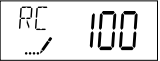
| RC | Fixed Reserve Capacity | Fixed volume to be used as a reserve | |
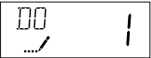
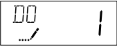
| DO | Day Override | The system’s day override setting | |
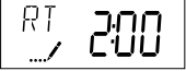
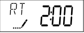
| RT | Regen Time | The time of day the system will regenerate | |
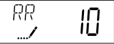
| BW, BD, RR, BF | Regen Cycle Step Times | The time duration for each regeneration step. Adjustable from OFF and 0-199 minutes. NOTE: If “Othr” is chosen under “Valve Type”, then R1, R2, R3, etc, will be displayed instead | |
| D1, D2, D3, D4, D5, D6, & D7 | Day of Week Settings | Regeneration setting (On or OFF) for each day of the week on day-of-week systems | |
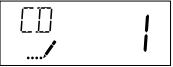
| CD | Current Day | The Current day of the week | |
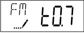
| FM | Flow Meter Type | t0.7 | 3/4-inch Turbine Meter |
| P0.7 | 3/4-inch Paddle Wheel Meter | ||
| t1.0 | 1-inch Turbine Meter | ||
| P1.0 | 1-inch Paddle Wheel Meter | ||
| t1.5 | 1.5-inch Turbine Meter | ||
| P1.5 | 1.5-inch Paddle Wheel Meter | ||
| P2.0 | 2-inch Paddle Wheel Meter | ||
| Gen | Generic or Other Meter | ||
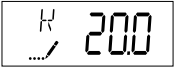
| K | Meter Pulse Setting | Meter pulses per gallon for generic/other flow meter |
NOTE: Some items may not be shown depending on timer configuration. The timer will discard any changes and exit Master Programming Mode if any button is not pressed for sixty seconds.
• FLECK 5600SXT Downflow Service Manual
MASTER PROGRAMMING MODE
When the Master Programming Mode is entered, all available option setting displays may be viewed and set as needed. Depending on current option settings, some parameters cannot be viewed or set.
Setting the Time of Day
- Press and hold either the Up or Down buttons until the programming icon replaces the service icon and the parameter display reads TD.
- Adjust the displayed time with the Up and Down buttons.
- When the desired time is set, press the Extra Cycle button to resume normal operation. The unit will also return to normal operation after 5 seconds if no buttons are pressed.
Entering Master Programming Mode
Set the Time Of Day display to 12:01 PM. Press the Extra Cycle button (to exit Setting Time of Day mode). Then press and hold the Up and Down buttons together until the programming icon replaces the service icon and the Display Format screen appears.
Exiting Master Programming Mode
Press the Extra Cycle button to accept the displayed settings and cycle to the next parameter. Press the Extra Cycle button at the last parameter to save all settings and return to normal operation. The control will automatically disregard any programming changes and return to normal operation if it is left in Master Programming mode for 5 minutes without any keypad input.
Resets
Soft Reset: Press and hold the Extra Cycle and Down buttons for 25 seconds while in normal Service mode. This resets all parameters to the system default values, except the volume remaining in meter immediate or meter delayed systems and days since regeneration in the time clock system.
Master Reset: Hold the Extra Cycle button while powering up the unit. This resets all of the parameters in the unit. Check and verify the choices selected in Master Programming Mode.
1.Display Format (Display Code DF)
This is the first screen that appears when entering Master Programming Mode. The Display Format setting specifies the unit of measure that will be used for volume and how the control will display the Time of Day. This option setting is identified by “DF” in the upper left hand corner of the screen. There are two possible settings:
| Display Format Setting | Unit of Volume | Time Display |
| GAL | U.S. Gallons | 12-Hour AM/PM |
| Ltr | Liters | 24-Hour |

2.Valve Type (Display Code VT)
Press the Extra Cycle button. Use this display to set the Valve Type. The Valve Type setting specifies the type of cycle that the valve follows during regeneration. Note that some valve types require that the valve be built with specific subcomponents. Ensure the valve is configured properly before changing the Valve Type setting. This option setting is identified by “VT” in the upper left hand corner of the screen. There are six possible settings:
| Abbreviation | Parameter |
| dF1b | Downflow/Upflow, Single Backwash |
| dF2b | Downflow Double Backwash |
| Fltr | Filter |
| UFbd | Upflow Brine First |
| UFtr | Upflow Filter |
| Othr | Other |

3.Control Type (Display Code CT)
Press the Extra Cycle button. Use this display to set the Control Type. This specifies how the control determines when to trigger a regeneration. For details on how the various options function, refer to the “Timer Operation” section of this service manual. This option setting is identified by “CT” in the upper left hand corner of the screen. There are four possible settings:
Meter Delayed: Fd
Meter Immediate: FI
Time Clock: tc
Day of Week: dAY

4.Number of Tanks (Display Code NT)
Press the Extra Cycle button. Use this display to set the Number of Tanks in your system. This option setting is identified by “NT” in the upper left hand corner of the screen. There are two possible settings:
Single Tank System: 1
Two-Tank System: 2

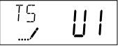
5.Tank in Service (Display Code TS)
Press the Extra Cycle button. Use this display to set whether tank one or tank two is in service. This option setting is identified by “TS” in the upper left hand corner of the screen. This parameter is only available if the number of tanks has been set to 2. There are two possible settings:
Tank One in Service: U1
Tank Two in Service: U2
6.Unit Capacity (Display Code C)
Press the Extra Cycle button. Use this display to set the Unit Capacity. This setting specifies the treatment capacity of the system media. Enter the capacity of the media bed in grains of hardness when configuring a softener system, and in the desired volume capacity when configuring a filter system. This option setting is identified by “C” in the upper left hand corner of the screen. The Unit Capacity parameter
is only available if the control type has been set to one of the metered options. Use the Up and Down buttons to adjust the value as needed.
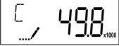
Range: 1-999,900 gallons (100-9,999,000 Liters)
7.Feedwater Hardness (Display Code H)
Press the Extra Cycle button. Use this display to set the Feedwater Hardness. Enter the feedwater hardness in grains per unit volume for softener systems, or 1 for filter systems. This option setting is identified by “H” in the upper left hand corner of the screen. The feedwater hardness parameter is only available if the control type has been set to one of the metered options. Use the Up and Down buttons to adjust the value as needed.
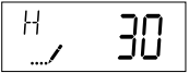
Range: 1-199 hardness
8.Reserve Selection (Display Code RS)
Press the Extra Cycle button. Use this display to set the Safety Factor. Use this display to select the type of reserve to be used in your system. This setting is identified by “RS” in the upper left-hand corner of the screen. The reserve selection parameter is only available if the control type has been set to one of the metered options. There are two possible settings.
| FS | Safety Factor |
| rc | Fixed Reserve Capacity |

FLECK 5600SXT Downflow Service Manual
9.Safety Factor (Display Code SF)
Press the Extra Cycle button. Use this display to set the Safety Factor. This setting specifies what percentage of the system capacity will be held as a reserve. Since this value is expressed as a percentage, any change to the unit capacity or feedwater hardness that changes the calculated system capacity will result in a corresponding change to the reserve volume. This option setting is identified by “SF” in the upper left hand corner of the screen. Use the Up and Down buttons to adjust the value from 0 to 50% as needed.
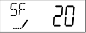
Range: 0-50%
10.Fixed Reserve Capacity (Display Code RC)
Press the Extra Cycle button. Use this display to set the Reserve Capacity. This setting specifies a fixed volume that will be held as a reserve. The reserve capacity cannot be set to a value greater than one-half of the calculated system capacity. The reserve capacity is a fixed volume and does not change if the unit capacity or feedwater hardness are changed. This option setting is identified by “RC” in the upper left-hand
corner of the screen. Use the Up and Down buttons to adjust the value as needed.
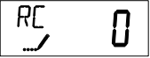
Range: 0-half the calculated capacity
11.Day Override (Display Code DO)
Press the Extra Cycle button. Use this display to set the Day Override. This setting specifies the maximum number of days between regeneration cycles. If the system is set to a timer- type control, the day override setting determines how often the system will regenerate. A metered system will regenerate regardless of usage if the days since last regeneration cycle equal the day override setting. Setting the day override value to “OFF” disables this function. This option setting is identified by “DO” in the upper left hand corner of the screen. Use the Up
and Down buttons to adjust the value as needed.
12.Regeneration Time
Press the Extra Cycle button. Use this display to set the Regeneration Time. This setting specifies the time of day the control will initiate a delayed, manually queued, or day override triggered regeneration. This option setting is identified by “RT” in the upper left hand corner of the screen. Use the Up and Down buttons to adjust the value as needed.
13.Regeneration Cycle Step Times
Press the Extra Cycle button. Use this display to set the Regeneration Cycle Step Times. The different regeneration cycles are listed in sequence based on the valve type selected for the system, and are identified by an abbreviation in the upper left-hand corner of the screen. The abbreviations used are listed below. If the system has been configured with the “OTHER” valve type, the regeneration cycles will be identified as R1, R2, R3, R4, R5, and R6. Each cycle step time can be set from 0 to 199 minutes. Setting a cycle step time to 0 will cause
the control to skip that step during regeneration, but keeps the following steps available. Use the Up and Down buttons to adjust the value as needed. Press the Extra Cycle button to accept the current setting and move to the next parameter.
| Abbreviation | Cycle Step |
| BD | Brine Draw |
| BF | Brine Fill |
| BW | Backwash |
| RR | Rapid Rinse |
| SV | Service |
14.Day of Week Settings
Press the Extra Cycle button. Use this display to set the regeneration schedule for a system configured as a Day of Week control. The different days of the week are identified as D1, D2, D3, D4, D5, D6, and D7 in the upper left-hand corner of the display. Set the value to “ON” to schedule a regeneration or “OFF” to skip regeneration for each day. Use the Up and Down buttons to adjust the setting as needed. Press the Extra Cycle button to accept the setting and move to the next day. Note that the control requires at least one day to be set to “ON.” If all 7 days are set to “OFF”, the unit will return to Day One until one or more days are set to “ON.”

15.Current Day (Display Code CD)
Press the Extra Cycle button. Use this display to set the current day on systems that have been configured as Day of Week controls. This setting is identified by “CD” in the upper left-hand corner of the screen. Use the Up and Down buttons to select from Day 1 through Day 7.
16.Flow Meter Type (Display Code FM)
Press the Extra Cycle button. Use this display to set the type of flow meter connected to the control. This option setting is identified by “FM” in the upper left-hand corner of the screen. Use the Up and Down buttons to select one of the seven available settings.
| t0.7 | Fleck 3/4-inch Turbine Meter |
| P0.7 | Fleck 3/4-inch Paddle Wheel Meter |
| t1.0 | Fleck 1-inch Turbine Meter |
| P1.0 | Fleck 1-inch Paddle Wheel Meter |
| t1.5 | Fleck 1-1/2 inch Turbine Meter |
| P1.5 | Fleck 1-1/2 inch Paddle Wheel Meter |
| P2.0 | Fleck 2-inch Paddle Wheel Meter |
| GEn | Generic/Other Meter |
17.Meter Pulse Setting (Display Code K)
Press the Extra Cycle button. Use this display to specify the meter pulse setting for a non-standard flow meter. This option setting is identified by “K” in the upper left-hand corner of the screen. Use the Up and Down buttons to enter the meter constant in pulses per unit volume.
18.End of Master Programming Mode
Press the Extra Cycle button to save all settings and exit Master Programming Mode.
USER PROGRAMMING MODE
| User Programming Mode Options | ||
| Abbreviation | Parameter | Description |
| DO | Day Override | The timer’s day override setting |
| RT | Regeneration Time | The time of day that the system will regenerate (meter delayed, time clock, and day-of-week systems) |
| H | Feed Water Hardness | The hardness of the inlet water – used to calculate system capacity for metered systems |
| RC or SF | Reserve Capacity | The fixed reserve capacity |
| CD | Current Day | The current day of week |
NOTE: Some items may not be shown depending on timer configuration. The timer will discard any changes and exit User Mode if any button is not pressed for sixty seconds.
User Programming Mode Steps
- Press the Up and Down buttons for five seconds while in service, and the time of day is NOT set to 12:01 PM.
- Use this display to adjust the Day Override. This option setting is identified by “DO” in the upper left hand corner of the screen.
- Press the Extra Cycle button. Use this display to adjust the Regeneration Time. This option setting is identified by “RT” in the upper left hand corner of the screen.
- Press the Extra Cycle button. Use this display to adjust the Feed Water Hardness. This option setting is identified by “H” in the upper left hand corner of the screen.

- Press the Extra Cycle button. Use this display to adjust the Fixed Reserve Capacity. This option setting is identified by “RC” or “SF” in the upper left-hand Corner of the screen.
FLECK 5600SXT Downflow Service Manual
- Press the Extra Cycle button. Use this display to set the Current Day of the Week. This option setting is identified by “CD” in the upper left hand corner of the screen.

- Press the Extra Cycle button to end User Programming Mode.
DIAGNOSTIC PROGRAMMING MODE
| Diagnostic Programming Mode Options | ||
| Abbreviation | Parameter | Description |
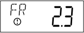
| FR | Flow Rate | Displays the current outlet flow rate |
| PF | Peak Flow Rate | Displays the highest flow rate measured since the last regeneration |
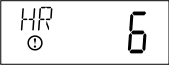
| HR | Hours in Service | Displays the total hours that the unit has been in service |
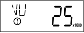
| VU | Volume Used | Displays the total volume of water treated by the unit |
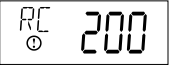
| RC | Reserve Capacity | Displays the system’s reserve capacity calculated from the system capacity, feedwater hardness, and safety factor |
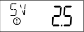
| SV | Software Version | Displays the software version installed on the controller |
NOTE: Some items may not be shown depending on timer configuration. The timer will exit Diagnostic Mode after 60 seconds if no buttons are pressed. Press the Extra Cycle button to exit Diagnostic Mode at any time.
Diagnostic Programming Mode Steps
- Press the Up and Extra Cycle buttons for five seconds while in service.
- Use this display to view the current Flow Rate. This option setting is identified by “FR” in the upper left hand corner of the screen.
- Press the Up button. Use this display to view the Peak Flow Rate since the last regeneration cycle. This option setting is identified by “PF” in the upper left hand corner of the screen.

- Press the Up button. Use this display to view the Hours in Service since the last regeneration cycle. This option setting is identified by “HR” in the upper left hand corner of the screen.
- Press the Up button. Use this display to view the Volume Used since the last regeneration cycle. This option setting is identified by “VU” in the upper left hand corner of the screen.
- Press the Up button. Use this display to view the Reserve Capacity. This option setting is identified by “RC” in the upper left hand corner of the screen.
- Press the Up button. Use this display to view the Software Version. This option setting is identified by “SV” in the upper left hand corner of the screen.
- Press the Extra Cycle button to end Diagnostic Programming Mode.
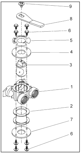
CONTROL VALVE ASSEMBLY
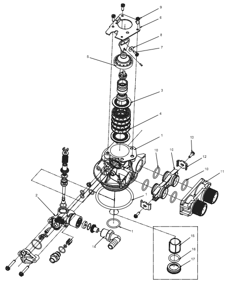
| Item No. | QTY | Part No. | Description |
| 1 | 1 | 61400-12 | Valve Body Assy, 5600, Downflow, w/TOT O-ring |
| 1 | 19700-10 | Valve Body, 5600, Downflow | |
| 1 | 12281 | O-ring, -338 | |
| 1 | 13304 | O-ring, -121 | |
| 2 | 1 | 60084 | Injector, Drain Assy, 5600 |
| 1 | 13163 | Housing, Injector and Drain | |
| 2 | 13301 | O-ring, 011 | |
| 1 | 12638 | O-ring, 013 | |
| 1 | 10227 | Screen, Injector | |
| 1 | 10913-1 | Nozzle, Injector, #1, Natural | |
| 1 | 10914-1 | Throat, Injector, #1, White | |
| 1 | 13166 | Cap, Injector, 5600 | |
| 1 | 13303 | O-ring, -021 | |
| 2 | 13315 | Screw, Hx Washer Head, 10-24 x 1-3/16-inch | |
| 1 | 15348 | O-ring, -563 | |
| 1 | 13173 | Retainer, DLFC Button | |
| 1 | 12088 | Washer Flow, 2.4 gpm | |
| 1 | 13172 | Brine Valve Stem | |
| 1 | 12626 | Seat, Brine Valve | |
| 1 | 13167 | Spacer, Brine Valve | |
| 1 | 13165 | Cap, Brine Valve | |
| 1 | 11973 | Spring, Brine Valve | |
| 1 | 11981-01 | E-ring | |
| 1 | 16098 | Washer, Nylon | |
| 1 | 12977 | O-ring, 015 | |
| 1 | 13245 | Retainer, BLFC | |
| 1 | 12095 | Washer, Flow Control, .50 gpm | |
| 1 | 12550 | Quad Ring, -009 | |
| 2 | 13302 | O-ring, -014 | |
| 1 | 13244 | Brine Line Flowcontrol Adapter | |
| 1 | 13497 | Disperser, Air, 5600 | |
| 1 | 13333 | Label, Injector, Blank | |
| 1 | BR10760 | Label, 1 gpm, 3 lbs. Salt/ min. | |
| 3 | 5 | 13242 | Seal, 5600 |
| 4 | 14241 | Spacer, 5600 | |
| 1 | 60102-71 | Piston Assy, 6600, Downflow | |
| 1 | 17218 | Piston, 6600 Downflow | |
| 1 | 14309 | Retainer, Piston Rod | |
| 1 | 13306 | Pin, Roll, 3/32 x 1/4 | |
| 1 | 13003 | Link, Piston Rod, 5600 | |
| 1 | 13243-40 | Plug, End, 6600, Green | |
| 1 | 13008 | Retainer, End Plug Seal | |
| 1 | 10209 | Quad Ring, -010 | |
| 6 | 1 | 13546 | Retainer, End Plug |
| 7 | 1 | 13296 | Screw, Hex Washer, 6-20 x 1/2 |
| 8 | 1 | 13363 | Washer, Plain, .145 ID SS |
| 9 | 3 | BR12112 | Screw, Slotted Hex Head, 10-24 x .50 |
| 10 | 2 | 19228-01 | Adapter Assy, Coupling, 5600 w/O-ring |
| 1 | 19228 | Coupling, Adapter | |
| 2 | 13305 | O-ring, -199 | |
| 11 | 1 | 18706 | Yoke, 1-inch, NPT, Plastic |
| 12 | 2 | 13255 | Clip, Mounting |
| 13 | 2 | BR13314 | Screw, Hx Washer Head, 8-18 x .60 |
| 14 | 1 | 12338 | Fitting, Elbow, 90 deg. |
| 15 | 1 | 13634 | Distributor, Pilot, Sleeve |
| 16 | 1 | 10244 | O-ring, -211 |
| 17 | 1 | 13633 | Distributor, Pilot Ring, 13/16-inch |
VALVE POWERHEAD ASSEMBLY
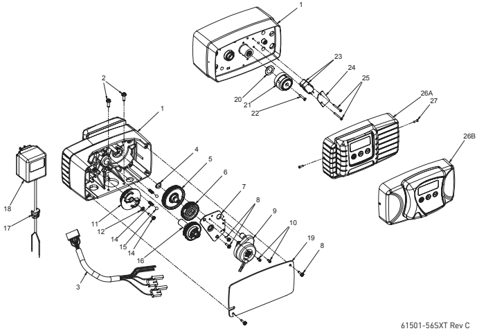
| Item No. | QTY | Part No. | Description |
| 1 | 1 | 14448-100 | Drive Housing Assy, with Pin, 56SXT |
| 2 | 2 | 12473 | Screw, Hex Wsh 10-24 x 5/8 |
| 3 | 1 | 19474 | Harness, Power, 56SXT, Elect |
| 4 | 1 | 13299 | Washer, Spring, 3/8 |
| 5 | 1 | 13017 | Gear, Idler |
| 6 | 1 | 23045 | Gear, Drive, 6700 |
| 7 | 1 | 13175 | Plate, Motor Mounting |
| 8 | 4 | 13296 | Screw, Hex Wsh, 6-20 x 1/2 |
| 9 | 1 | 16944 | Motor, Drive, 24V 60 Hz 2 rpm |
| 10 | 2 | 11384 | Screw, Phil, 6-32 x 1/4 Zinc |
| 11 | 1 | 18722 | Cam, Brine Valve, 56SXT/6700 Blk |
| 12 | 1 | 12037 | Washer, Plain, #10 18-8 Stainless Steel |
| 13 | 1 | 40214 | Screw, Hex Wsh, #6-20 x 3/4 |
| 14 | 2 | 19080 | Spring, Compression, 6700 |
| 15 | 2 | 13300 | Ball, 1/4-inch Stainless Steel |
| 16 | 1 | 42933 | Gear, Main Drive, Downflow |
| 17 | 1 | 13547 | Strain Relief, Flat Cord |
| 18 | 1 | 19674 | Transformer, 24V, 9.6VA,Residential Valves |
| 41475 | Transformer, 24V, 9.6VA, European | ||
| 19 | 1 | 40338 | Cover, Back Drive Housing |
| 20 | 1 | 19079 | Washer, Friction |
| 21 | 1 | 17438 | Cam, 56SXT/6700, Downflow |
| 40609 | Cam, Double Backwash, Downflow | ||
| 22 | 1 | 15151 | Screw, Flat Hd St, 6-20 x 3/4 |
| 23 | 2 | 10218 | Switch, Micro |
| 24 | 1 | 10302 | Insulator, Limit Switch |
| 25 | 2 | 17876 | Screw, Phil, Pan, 4-40 x 1-1/8 |
| 26A | 1 | 61672-0201 | Front Panel Assy, 56SXT, Square, Black |
| 26B | 1 | 61673-0201 | Front Panel Assy, 56SXT, Curved, Black |
| 27 | 2 | 13898 | Screw, Flat Hd, Phil Steel |
| Not Shown: | 4 | 40422 | Wire, Nut, Beige |
3/4-INCH TURBINE METER ASSEMBLY
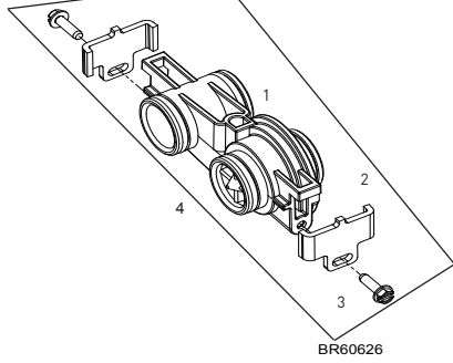
| Item No. | QTY | Part No. | Description |
| 1 | 1 | 19797 | .Meter Assy, 3/4″ Dual Port, SLP |
| 2 | 2 | 19569 | Clip, Flow Meter |
| 3 | 2 | 13314 | Screw, Slot Ind Hex, 8-18 x 0.60 |
| 4 | 1 | 60626 | 34″ Turbine, w/Clips & Screws |
| Not Shown: | 14613 | Flow Straightener | |
| 19121-01 | Meter Cable Assy, Turbine/ SXT |
3/4-INCH PLASTIC PADDLE METER ASSEMBLY
| Item No. | QTY | Part No. | Description |
| 1 | 1 | 14716 | Meter Cap Assy, NT (includes items 2, 3, and 4) |
| 2 | 1 | 13874 | Cap, Meter, Electronic |
| 3 | 1 | 13847 | O-ring, -137, Std, Meter |
| 4 | 1 | 17798 | Screw, Slot Hex Washer Head |
| 5 | 1 | 19121-01 | Meter Cable Assy, SXT, Paddle (not included in P/N 60086) |
| 6 | 1 | 13821 | Body, Meter, 5600 |
| 7 | 1 | 13509 | Impeller, Meter |
| 8 | 4 | 12473 | Screw, Hex Wsh, 10-24 x 5/8 |
| 9 | 4 | 13255 | Clip, Mounting |
| 10 | 4 | 13314 | Screw, Slot Ind Hex, 8-18 x 0.60 |
| 11 | 4 | 13305 | O-ring, -119 |
| 12 | 1 | 14613 | Flow Straightener |
| 13 | 1 | 60086-50 | Meter Assy, 3/4″, Elec, Paddlewheel |
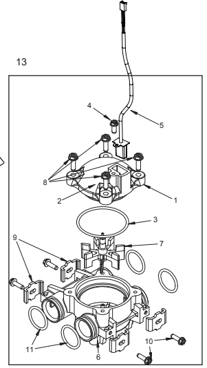
BYPASS VALVE ASSEMBLY (PLASTIC)
| Item No. | QTY | Part No. | Description |
| 1 | 2 | 13305 | O-ring, -119 |
| 2 | 2 | 13255 | Clip, Mounting |
| 3 | 2 | 13314 | Screw, Hex Washer Head, 8-18 x 5/8 |
| 4A | 1 | 18706 | Yoke, Plastic, 1-inch NPT |
| 18706-02 | Yoke, Plastic, 3/4-inch NPT | ||
| 4B | 1 | 13708 | Yoke, Brass, 3/4-inch NPT |
| 13708NP | Yoke, 3/4-inch NPT Nickel Plated | ||
| 13398 | Yoke, Brass, 1-inch NPT | ||
| 13398NP | Yoke, 1-inch NPT Nickel Plated | ||
| 40636 | Yoke, 1-1/4 inch NPT | ||
| 40636-49 | Yoke, 1-1/4 inch Sweat | ||
| 5 | 1 | 60049 | 3/4″ Bypass, Plastic |
BYPASS VALVE ASSEMBLY (METAL)
60041SS Rev T
| Item No. | QTY | Part No. | Description |
| 1 | 1 | 17290 | Bypass Valve Body, 3/4-inch |
| 17290NP | Bypass Valve Body, 3/4-inch Nickel Plated | ||
| 13399 | Bypass Valve Body, 1-inch | ||
| 13399NP | Bypass Valve Body, 1-inch, Nickel Plated | ||
| 2 | 1 | 11726 | Seal, Bypass |
| 3 | 1 | 11972 | Plug, Bypass |
| 4 | 1 | 11978 | Side Cover |
| 5 | 1 | 13604-01 | Label |
| 6 | 8 | 15727 | Screw |
| 7 | 1 | 11986 | Side Cover |
| 8 | 1 | 11979 | Lever, Bypass |
| 9 | 1 | 11989 | Screw, Hex Head, 1/4-14 |
| 10 | 1 | 60040SS | Bypass, 3/4″, S.S. |
| 6041SS | Bypass, 1″, S.S. |
2300 SAFETY BRINE VALVE
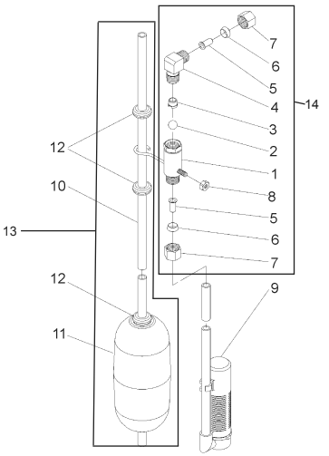
| Item No. | QTY | Part No. | Description |
| 1 | 1 | 11942 | Brine Valve Body 1/4-inch NPT |
| 2 | 1 | 10138 | Ball, 3/8-inch |
| 3 | 1 | 11566 | Bull Stop |
| 4 | 1 | 10328 | Elbow, 1/4-inch x 1/4-inch T |
| 5 | 2 | 10332 | Insert, 3/8-inch |
| 6 | 2 | 10330 | Sleeve, 3/8-inch |
| 7 | 1 | 10329 | Tube Nut, 3/8-inch |
| 8 | 1 | 10186 | Nut, Hex, 10-32, Nylon |
| 9 | 1 | 60002-34 | #500 Air Check |
| 10 | 1 | 10149 | Float Rod, 30-inch |
| 11 | 1 | 10700 | Float Assembly, White |
| 12 | 4 | 10150 | Grommet |
| 13 | 1 | 60028-30 | Float Assy, 2300, 30″, White |
| 14 | 1 | 60027-FFA | Safety Brine Valve, 2300, Fitting Facing Arm |
| 15 | 1 | 60027-FFS | Safety Brine Valve, 2300, Fitting Facing Stud |
2310 SAFETY BRINE VALVE
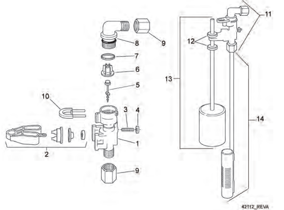
| Item No. | QTY | Part No. | Description |
| 1 | 1 | 19645 | Safety Brine Valve Body |
| 2 | 1 | 19803 | Safety Brine Valve Arm Assembly |
| 3 | 1 | 19804 | Stud, 10-24 |
| 4 | 1 | 19805 | Nut, 10-24 |
| 5 | 1 | 19652-01 | Poppet and Seal |
| 6 | 1 | 19649 | Flow Dispenser |
| 7 | 1 | 11183 | O-ring, 017 |
| 8 | 1 | 19647 | Elbow, Safety Brine Valve |
| 9 | 2 | 19625 | Nut Assembly, 3/8 |
| 10 | 1 | 18312 | Retaining Clip |
| 11 | 1 | 60014 | Grommet (included with item 13) |
| 12 | 2 | 10150 | Grommet |
| 13 | 1 | 60068-30 | Float Assembly, 2310, w/30-inch Rod |
| 14 | 1 | 60002-34 | Air Check, #500, 34-inch long |
TROUBLESHOOTING
| Problem | Cause | Correction |
| Water conditioner fails to regenerate. | Electrical service to unit has been interrupted | Assure permanent electrical service (check fuse, plug, pull chain, or switch) |
| Timer is defective. | Replace timer. | |
| Power failure. | Reset time of day. | |
| Hard water. | By-pass valve is open. | Close by-pass valve. |
| No salt is in brine tank. | Add salt to brine tank and maintain salt level above water level. | |
| Injector screen plugged. | Clean injector screen. | |
| Insufficient water flowing into brine tank. | Check brine tank fill time and clean brine line flow control if plugged. | |
| Hot water tank hardness. | Repeated flushings of the hot water tank is required. | |
| Leak at distributor tube. | Make sure distributor tube is not cracked. Check o-ring and tube pilot. | |
| Internal valve leak. | Replace seals and spacers and/or piston. | |
| Unit used too much salt. | Improper salt setting. | Check salt usage and salt setting. |
| Excessive water in brine tank. | See “Excessive water in brine tank”. | |
| Loss of water pressure. | Iron buildup in line to water conditioner. | Clean line to water conditioner. |
| Iron buildup in water conditioner. | Clean control and add mineral cleaner to mineral bed. Increase frequency of regeneration. | |
| Inlet of control plugged due to foreign material broken loose from pipes by recent work done on plumbing system. | Remove piston and clean control. | |
| Loss of mineral through drain line. | Air in water system. | Assure that well system has proper air eliminator control. Check for dry well condition. |
| Improperly sized drain line flow control. | Check for proper drain rate. | |
| Iron in conditioned water. | Fouled mineral bed. | Check backwash, brine draw, and brine tank fill. Increase frequency of regeneration. Increase backwash time. |
| Excessive water in brine tank. | Plugged drain line flow control. | Clean flow control. |
| Plugged injector system. | Clean injector and screen. | |
| Timer not cycling. | Replace timer. | |
| Foreign material in brine valve. | Replace brine valve seat and clean valve. | |
| Foreign material in brine line flow control. | Clean brine line flow control. | |
| Softener fails to draw brine. | Drain line flow control is plugged. | Clean drain line flow control. |
| Injector is plugged. | Clean injector | |
| Injector screen plugged. | Clean screen. | |
| Line pressure is too low. | Increase line pressure to 20 psi | |
| Internal control leak | Change seals, spacers, and piston assembly. | |
| Service adapter did not cycle. | Check drive motor and switches. | |
| Control cycles continuously. | Misadjusted, broken, or shorted switch. | Determine if switch or timer is faulty and replace it, or replace complete power head. |
| Drain flows continuously. | Valve is not programming correctly. | Check timer program and positioning of control. Replace power head assembly if not positioning properly. |
| Foreign material in control. | Remove power head assembly and inspect bore. Remove foreign material and check control in various regeneration positions. | |
| Internal control leak. | Replace seals and piston assembly. |
Error Codes
NOTE: Error codes appear on the In Service display.
| Error Code | Error Type | Cause | Reset and Recovery |
| 0 | Cam Sense Error | The valve drive took longer than 6 minutes to advance to the next regeneration position | Unplug the unit and examine the powerhead. Verify that all cam switches are connected to the circuit board and functioning properly. Verify that the motor and drive train components are in good condition and assembled properly. Check the valve and verify that the piston travels freely. Replace/reassemble the various components as necessary. Plug the unit back in and observe its behavior. The unit should cycle to the next valve position and stop. If the error re-occurs, unplug the unit and contact technical support. |
| 1 | Cycle Step Error | The control experienced an unexpected cycle input | Unplug the unit and examine the powerhead. Verify that all cam switches are connected to the circuit board and functioning properly. Enter Master Programming mode and verify that the valve type and system type are set correctly with regard to the unit itself. Step the unit through a manual regeneration and verify that it functions correctly. If the error re-occurs unplug the unit and contact technical support. |
| 2 | Regen Failure | The system has not regenerated for more than 99 days (or 7 days if the Control Type has been set to Day-of- Week) | Perform a Manual Regeneration to reset the error code. If the system is metered, verify that it is measuring flow by running service water and watching for the flow indicator on the display. If the unit does not measure flow, verify that the meter cable is connected properly and that the meter is functioning properly. Enter a Master Programming Mode and verify that the unit is configured properly. As appropriate for the valve configuration, check that the correct system capacity has been selected, that the day override is set properly, and that meter is identified correctly. If the unit is configured as a Day-of-Week system, verify that at least one day is set ON. Correct the settings as necessary. |
| 3 | Memory Error | Control board memory failure | Perform a Master Reset and reconfigure the system via Master Programming Mode. After reconfiguring the system, step the valve through a manual regeneration. If the error re-occurs unplug the unit and contact technical support. |
| UD | Upper Drive Sync | Power failure install programming change | Valve will automatically recover. |
WATER CONDITIONER FLOW DIAGRAMS
| Single Backwash Positions Black Cycle Cam (Part Number 17438) | Double Backwash Positions Blue Cycle Cam (Part Number 40609) |
| Service Position | Service Position |
| 1.Backwash Position | 1.First Backwash Position |
| 2.Brine/Slow Rinse Position | 2.Brine/Slow Rinse Position |
| 3.Rapid Rinse Position | 3.Second Backwash Position |
| 4.Brine Tank Fill Position | 4.Rapid Rinse Position |
| Service Position | 5.Brine Tank Fill Position |
| Service Position |
Service Position
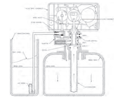
Backwash Position
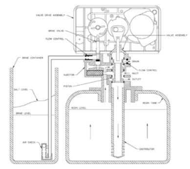
Brine/Slow Rinse Position
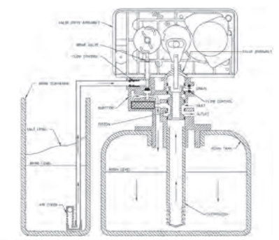
Second Backwash Position (Double Backwash Units Only)
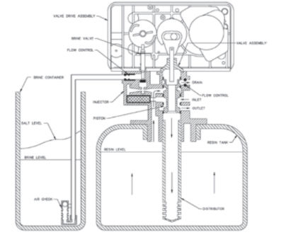
Rapid Rinse
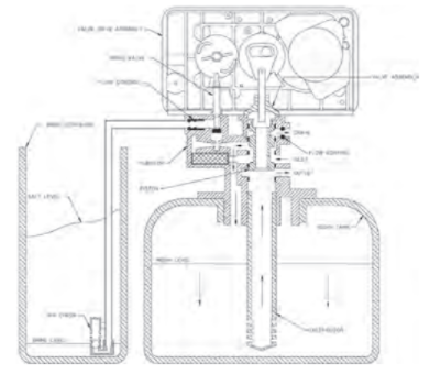
Brine Tank Fill Position
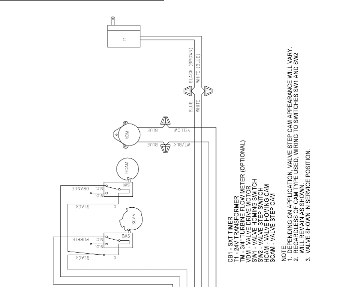
WIRING DIAGRAM
SERVICE INSTRUCTIONS
Replacing Brine Valve, Injectors and Screen
- Turn off water supply to conditioner: If the conditioner installation has a “three valve” bypass system, first open the valve in the bypass line, then close the valves at the conditioner inlet and outlet. If the conditioner has an integral bypass valve, put it in the
Bypass position. If there is only a shut-off valve near the conditioner inlet, close it. - Relieve water pressure in the conditioner by stepping the control into the Backwash position momentarily. Return the control to the In Service position.
- Unplug electrical cord from outlet.
- Disconnect brine tube and drain line connections at the injector body.
- Remove the two injector body mounting screws. The injector and brine module can now be removed from the control valve. Remove and discard brine body O-rings.
Brine Valve Replacement
- Pull brine valve from injector body. Also remove and discard o-ring at bottom of brine valve hole.
- Apply silicone lubricant to new o-ring and reinstall at bottom of brine valve hole.
- Apply silicone lubricant to o-ring on new valve assembly and press into brine valve hole. Be sure shoulder on bushing is flush with injector body.
Injectors/Screen Replacement
- Remove injector cap and screen, discard o-ring. Unscrew injector nozzle and throat from injector body.
- Screw in new injector throat and nozzle, be sure they are sealed tightly. Install a new screen.
- Apply silicone lubricant to new o-ring and install around oval extension on injector cap.
- Apply silicone lubricant to three new O-rings and install over three bosses on injector body.
- Insert screws thorough injector cap and injector. Place this assembly thorough hole in timer housing and into mating holes in the valve body. Tighten screws.
- Reconnect brine tube and drain line.
- Return bypass or inlet valve to normal In Service position. Water pressure automatically builds in the conditioner
NOTE: Be sure to shut off any bypass line.
- Check for leaks at all seal areas. Check drain seal with the control in the Backwash position.
- Plug electrical cord into outlet.
- Set Time Of Day and cycle the control valve manually to assure proper function. Make sure control valve is returned to the In Service position.
- Be sure there is enough salt in the brine tank.
- Start regeneration cycle manually if water is hard.
Timer Replacement
To replace timer refer to Replacing Brine Valve, Injectors and Screen, steps 1–3.
- Remove the control valve back cover. Remove the control valve front cover. Disconnect the meter dome signal wire from the front cover and feed it back through the control.
- Remove screw and washer at drive yoke. Remove timer mounting screws. The entire timer assembly then lifts off easily.
- Put new timer on top of valve. Be sure drive pin on main gear engages slot in drive yoke.
- Replace timer mounting screws. Replace screw and washer at drive yoke. Replace meter signal wire.
- Return bypass or inlet valve to normal In Service position. Water pressure automatically builds in the conditioner.
NOTE: Be sure to shut off any bypass line.
- Replace the control valve back cover.
- Follow Injectors/Screen Replacement, steps 9–12.
Piston Assembly Replacement
To replace piston assembly refer to Replacing Brine Valve, Injectors and Screen, steps 1–3.
- Remove the control valve back cover. Remove the control valve front cover. Disconnect the meter dome signal wire from the front cover and feed it back through the control.
- Remove screw and washer at drive yoke. Remove timer mounting screws. The entire timer assembly will now lift off easily. Remove end plug retainer plate.
- Pull upward on end of piston yoke until assembly is out of valve.
- Inspect the inside of the valve to make sure that all spacers and seals are in place, and that there is no foreign matter that would interfere with the valve operation.
- Take new piston assembly as furnished and push piston into valve by means of the end plug. Twist yoke carefully in a clockwise direction to properly align it with drive gear. Replace end plug retainer plate.
- Place timer on top of valve. Be sure drive pin on main gear engages slot in drive yoke.
- Replace timer mounting screws. Replace screw and washer at drive yoke.
- Return bypass or inlet valve to normal In Service position. Water pressure automatically builds in the conditioner
NOTE: Be sure to shut off any bypass line.
- Replace the control valve back cover.
- Follow Injectors/Screen Replacement, steps 9–12.
Seal and Spacer Replacement
To replace seals and spacers, refer to Replacing Brine Valve, Injectors and Screen, steps 1–3.
- Remove the control valve back cover. Remove the control valve front cover. Disconnect the meter dome signal wire from the front cover and feed it back through the control.
- Remove screw and washer at drive yoke. Remove timer mounting screws. The entire timer assembly will now lift off easily. Remove end plug retainer plate.
- Pull upward on end of piston rod yoke until assembly is out of valve. Remove and replace seals and spacers.
- Take piston assembly and push piston into valve by means of the end plug. Twist yoke carefully in a clockwise direction to properly align it with drive gear. Replace end plug retainer plate.
- Place timer on top of valve. Be sure drive pin on main gear engages slot in drive yoke.
- Replace timer mounting screws. Replace screw and washer at drive yoke.
- Return bypass or inlet valve to normal In Service position. Water pressure automatically builds in the conditioner.
NOTE: Be sure to shut off any bypass line.
- Replace the control valve back cover.
- Follow Injectors/Screen Replacement, steps 9–12.
Meter Replacement
To replace meter refer to Replacing Brine Valve, Injectors and Screen, steps 1–3.
- Remove two screws and clips at bypass valve or yoke. Pull resin tank away from plumbing connections.
- Pull meter module out of control valve.
- Remove signal wire from meter module, (snap tab on end opposite wire cable).
- Apply silicone lubricant to four new O-rings and assemble to four ports on new meter module.
- Install signal wire into new meter module.
- Assemble meter to control valve. Note, meter portion of module must be assembled at valve outlet.
- Push resin tank back to the plumbing connections and engage meter ports with bypass valve or yoke.
- Attach two clips and screws at bypass valve or yoke. Be sure clip legs are firmly engaged with lugs.
- Return bypass or inlet valve to normal In Service position. Water pressure automatically builds in the conditioner.
NOTE: Be sure to shut off any bypass line.
- Check for leaks at all seal areas.
- Follow Injectors/Screen Replacement, steps 9–12.
FLOW DATA & INJECTOR DRAW RATES
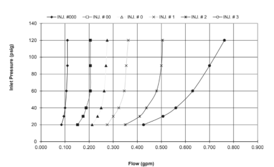
BRINE DRAW
SLOW RINSE
TOTAL FLOW
READ ALSO: ECO SMART TANKLESS WATER HEATER USER’S MANUAL
SERVICE ASSEMBLIES
Air Check
60002-34 …………………Air Check #500 34-inch
Brine Line Flow Controls
60022-12 …………………BLFC .125 gpm
60022-25 …………………BLFC .25 gpm
60022-50 …………………BLFC .50 gpm
60022-100 ……………….BLFC 1.0 gpm
Brine Line Flow Control Washers
17307 ………………………Washer Flow .125 gpm
12094 ………………………Washer Flow .25 gpm
12095 ………………………Washer Flow .50 gpm
12097 ………………………Washer Flow 1.0 gpm
Brine Valve Assembly
60032 ………………………Brine Valve
Bypasses
60040 ………………………Bypass, 3/4-inch, Brass
60040NP ………………….Bypass, 3/4-inch, Nickel
60041 ………………………Bypass, 1-inch, Brass
60041NP ………………….Bypass, 1-inch, Nickel
60049 ………………………Bypass, Plastic, 3/4-inch
Drain Line Flow Control Washers
19151 ………………………Washer Flow 1.0 gpm
12085 ………………………Washer Flow 1.2 gpm
12086 ………………………Washer Flow 1.5 gpm
12087 ………………………Washer Flow 2.0 gpm
12088 ………………………Washer Flow 2.4 gpm
12089 ………………………Washer Flow 3.0 gpm
12090 ………………………Washer Flow 3.5 gpm
12091 ………………………Washer Flow 4.0 gpm
12092 ………………………Washer Flow 5.0 gpm
Floats
60068-30 …………………Float Assy 2310 w/30-inch Rod
60028-30 …………………Float Assy 2300 30-inch White
Front Panels
61672-0201 ………………5600SXT Front Panel Assembly, Square, Black
61673-0201 ………………5600SXT Front Panel Assembly, Curved, Black
Injector
60084-XXXX ……………..Injector, Module Assembly (Specify Injector Number, DLFC Size, BLFC Size)
Injector # DLFC # BLFC #
Red #0………….. 00…………. Blank……… 0…………. Blank……. 0
White #1……….. 01…………. 1.2 …………. 1…………. 0.25 ……… 1
Blue #2 ………… 02…………. 1.5 …………. 2…………. 0.50 ……… 2
Yellow #3 ……… 03…………. 2.0 …………. 3…………. 1.00 ……… 3
Green #4………. 04…………. 2.4 …………. 4
3.0 …………. 5
3.5 …………. 6
4.0 …………. 7
5.0 …………. 8
7.0 …………. 9
Meter
60626 ………………………5600SXT Meter Assembly
Piston Assembly
60102-71 …………………5600SXT Piston Assembly, Downflow
Safety Brine Valves
60027-FFA ……………….Safety Brine Valve Body 2300 Fitting Facing Arm
60027-FFS ……………….Safety Brine Valve Body 2300 Fitting Facing Stud
60014 ………………………Safety Brine Valve Assembly 2310
Seal & Spacer Kits
60125 ………………………5600SXT Seal and Spacer Kit
60125-20 …………………Seal & Spacer Kit, Top
Yokes
13708-40 …………………Yoke 1-inch Sweat
13708-45 …………………Yoke 3/4-inch Sweat
18706 ………………………Yoke 1-inch NPT Plastic
18706-02 …………………Yoke, 3/4-inch NPT Plastic
19275 ………………………Yoke Angle 90 Deg 3/4-inch NPT
19275-45 …………………Yoke Angle 90 Deg 3/4-inch Sweat
19620-01 …………………Yoke Assy 3/4-inch R/Angle 90 Deg w/O-rings Clips and Screws
40636 ………………………Yoke 1-1/4 inch NPT
40636-49 …………………Yoke 1-1/4 inch Sweat
41026-01 …………………Yoke 1-inch NPT Cast Machined Stainless Steel
41027-01 …………………Yoke 3/4-inch NPT Cast Machined
For Fleck Product Warranties visit: www.pentairaqua.com/pro
Fleck para las garantías de los productos visite: www.pentairaqua.com/pro
Pour Fleck garanties produit visitez le site : www.pentairaqua.com/pro
FILTRATION & PROCESS
5730 NORTH GLEN PARK ROAD, MILWAUKEE, WI 53209
P: 262.238.4400 | WWW.PENTAIRAQUA.COM | CUSTOMER CARE: 800.279.9404 | tech-support@pentair.com
All Pentair trademarks and logos are owned by Pentair, Inc. or its affiliates. All other registered and unregistered trademarks and logos are the property of their respective owners. Because we are continuously improving our products and services. Pentair reserves the right to change specifications without prior notice. Pentair is an equal opportunity employer. 42684 REV H JA15 © 2015 Pentair Residential Filtration, LLC All Rights Reserved.
You can download the PDF version of the Pure Aqua Reverse Osmosis & Water Treatment Systems User’s Manual here.