QUESTIONS?
As a manufacturer, we are committed to providing complete customer satisfaction. If you have questions, or if parts are damaged or missing, PLEASE DO NOT CONTACT THE STORE; please contact Customer Care.
IMPORTANT: You must note the product model number and serial number (see the drawing above) before contacting us:
CALL TOLL-FREE:
1-888-825-2588
Mon.-Fri. 6 a.m.-6 p.m. MST
Sat. 8 a.m.—4 p.m. MST
ON THE WEB:
www.nordictrackservice.com
CAUTION
Read all precautions and instructions in this manual before using this equipment. Keep this manual for future reference.
Visit our website at www.nordictrack.com new products, prizes, fitness tips, and much more!
WARNING DECAL PLACEMENT
The warning decal shown here has been applied in the location shown. If the decal is missing or illegible, call the telephone number on the front cover of this manual and request a free replacement decal. Apply the decal in the location shown. Note: The decal may not be shown at actual size.
WARNING
- Misuse of this machine may result in serious injury.
- Read user’s manual prior to use and follow instructions.
- Do not allow children on or around machine.
- Pedals continue to spin when you stop pedaling.
- Spinning pedals can cause injury.
- Reduce pedal speed in a controlled manner.
- User weight must not exceed 250 pounds.
- Replace label if damaged, Illegible, or removed.
NordicTrack is a registered trademark of ICON IP, Inc.
IMPORTANT PRECAUTIONS
WARNING: To reduce the risk of serious injury, read all important precautions and instructions in this manual and all warnings on your elliptical exerciser before using your elliptical exerciser. ICON assumes no responsibility for personal injury or property damage sustained by or through the use of this product.
- Before beginning any exercise program, consult your physician. This is especially important for persons over the age of 35 or persons with pre-existing health problems.
- It is the responsibility of the owner to ensure that all users of the elliptical exerciser are adequately informed of all precautions.
- Your elliptical exerciser is intended for home use only. Do not use your elliptical exerciser in a commercial, rental, or institutional setting.
- Keep your elliptical exerciser indoors, away from moisture and dust. Place your elliptical exerciser on a level surface, with a mat beneath it to protect the floor or carpet. Make sure that there is enough clearance around your elliptical exerciser to mount, dismount, and use it.
- Inspect and properly tighten all parts regularly. Replace any worn parts immediately.
- Keep children under age 12 and pets away from your elliptical exerciser at all times.
- Your elliptical exerciser should not be used by persons weighing more than 250 lbs.(113 kg).
- Wear appropriate exercise clothes when exercising; do not wear loose clothes that could become caught on your elliptical exerciser. Always wear athletic shoes for foot protection.
- Hold the handgrip pulse sensor or the handlebars when mounting, dismounting, or using your elliptical exerciser.
- Keep your back straight while using your elliptical exerciser; do not arch your back.
- The pulse sensor is not a medical device. Various factors, including the user’s movement, may affect the accuracy of heart rate readings. The pulse sensor is intended only as an exercise aid in determining heart rate trends in general.
- When you stop exercising, allow the pedals to slowly come to a stop.
- If you feel pain or dizziness while exercising, stop immediately and cool down.
- Use your elliptical exerciser only as described in this manual.
BEFORE YOU BEGIN
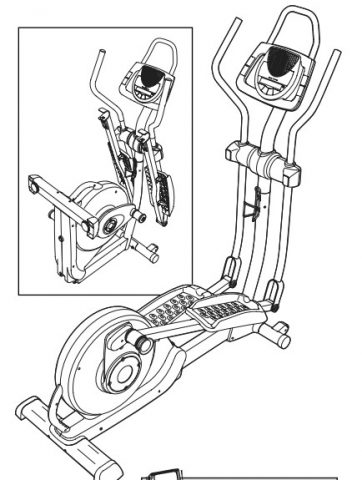
Thank you for selecting the revolutionary NordicTrack® CX1000 elliptical exerciser. The CX1000 elliptical exerciser provides a wide array of features designed to make your workouts at home more effective and enjoyable—and when you’re not exercising, the unique CX1000 elliptical exerciser can be folded out of the away.
For your benefit, read this manual carefully before you use the elliptical exerciser. If you have questions after reading this manual, please see the front cover of this manual. To help us assist you, note the product model number and serial number before contacting us. The model number and the location of the serial number decal are shown on the front cover of this manual.
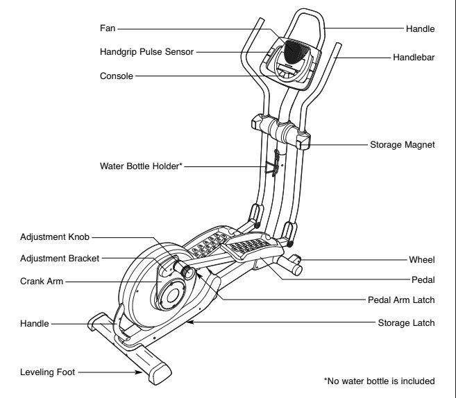
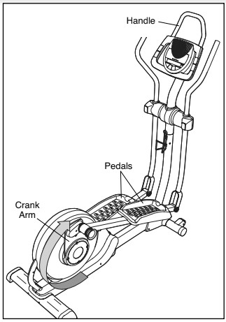
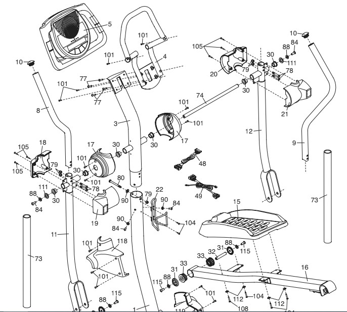
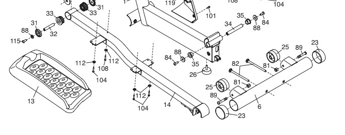
Before reading further, please familiarize yourself with the parts that are labeled in the drawing below.
ASSEMBLY
Assembly requires two persons. Place all parts of the elliptical exerciser in a cleared area and remove the packing materials. Do not dispose of the packing materials until assembly is completed. In addition to the included hex keys, assembly requires a Phillips screwdriver, an adjustable wrench, and a rubber mallet.
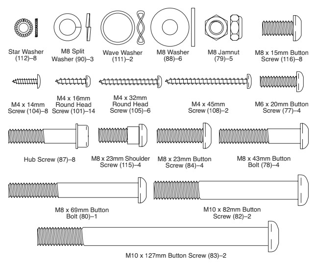
As you assemble the elliptical exerciser, use the drawings below to identify small parts. The number in parentheses below each drawing is the key number of the part, from the PART LIST near the end of this manual. The number following the parentheses is the quantity needed for assembly. Note: Some small parts may have been preassembled. If a part is not in the hardware kit, check to see if it has been preassembled.
- To make assembly easier, read the information on page above before you begin assembling the elliptical exerciser.
While another person lifts the Base (1), attach the Front Stabilizer (6) to the Base with two M10 x 82mm Button Screws (82).
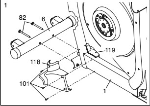
Next, hold the Left Stabilizer Cover (118) and the Right Stabilizer Cover (119) around the Base (1). Attach the Stabilizer Covers with six M4 x 16mm Round Head Screws (101) (only three are shown).
- Remove the indicated screw and the bracket from the Base (1). Discard the screw and the bracket.
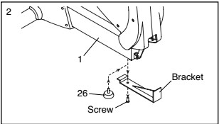
Next, turn the Base Foot (26) into the Base (1) as far as possible.
- Attach the Rear Stabilizer (7) to the Frame (2) with two M10 x 127mm Button Screws (83).
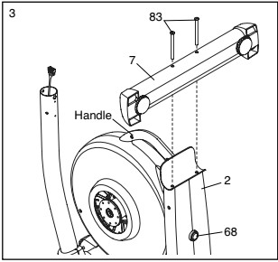
Next, hold the handle on the Frame (2), press the Latch Button (68), and lower the Frame until the Rear Stabilizer (7) is resting on the floor.
- Identify the Left Crank Arm (36), which is marked with a sticker. Hold the Left Crank Arm against the left Crank Hub (38), and align the holes in the Left Crank Arm with the unused holes in the Crank Hub. Next, insert four Hub Screws (87) into the Left Crank Arm, and finger tighten the Hub Screws into the Crank Hub. Tighten one of the Hub Screws, and then tighten the Hub Screw farthest from the first Hub Screw. Then, tighten the remaining two Hub Screws.
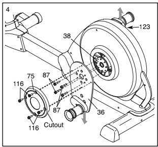
Attach a Hub Cover (75) to the Left Crank Arm (36) with four M8 x 15mm Button Screws (116).
Repeat this step on the other side of the elliptical exerciser. Make sure that the Crank Arms (36,123) are oriented as shown.
- While another person holds the Upright (3), connect the Upper Wire Harness (48) to the Lower Wire Harness (49). Gently pull the upper end of the Upper Wire Harness to remove any slack, and insert the Upright into the Base (1). Attach the Upright with an M8 x 69mm Button Bolt (80), an M8 Split Washer (90), and an M8 Jam Nut (79). Do not tighten the Button Bolt yet; make sure that the Jam Nut is in the hexagonal hole in the Base.
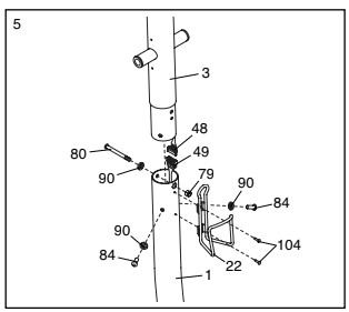
Next, finger tighten two M8 x 23mm Button Screws (84) with M8 Split Washers (90) into the Base (1). Do not tighten the Button Screws yet.
Attach the Water Bottle Holder (22) to the Base (1) with two M4 x 14mm Screws (104).
- Insert the end of the Upper Wire Harness (48) through the rectangular hole in the Console Bracket(4). Attach the Console Bracket to the Upright (3) with four M6 x 20mm Button Screws (77).
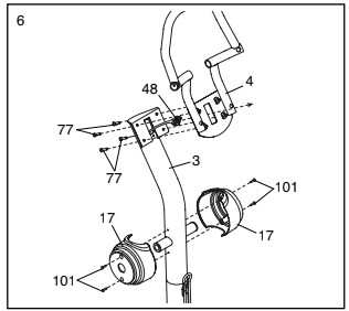
Orient one of the Upright Covers (17) as shown, and hold it against the Upright (3). Attach the Upright Cover with two M4 x 16mm Round Head Screws (101). Attach the other Upright Cover in the same way.
- The Console (5) requires four 1.5V “D” batteries (not included); alkaline batteries are recommended.
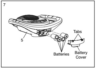
IMPORTANT: If the elliptical exerciser has been exposed to cold temperatures, allow it to warm to room temperature before inserting batteries into the Console. If you do not do this, the console displays or other electronic components may become damaged. Press the two tabs on the battery cover, and remove the battery cover. Next, insert four batteries into the Console. Make sure that the batteries are oriented as shown by the diagrams inside of the battery compartments. Then, reattach the battery cover to the Console.
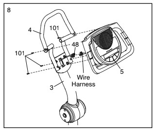
- While another person holds the Console (5) near the Console Bracket (4), connect the wire harness on the Console to the Upper Wire Harness (48). Insert the excess wire harness into the Upright (3). Next, attach the Console to the Console Bracket with four M4 x 16mm Round Head Screws (101). Be careful to avoid pinching the wire harness.
- Identify the Left Handlebar (8) and the Left Upper Body Arm (11), which are marked with stickers.
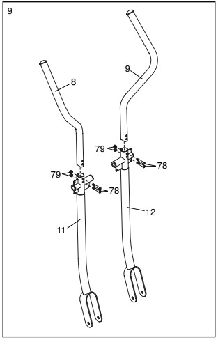
Orient the Left Handlebar (8) and the Left Upper Body Arm (11) as shown. Insert the Left Handlebar into the Left Upper Body Arm. Attach the Left Handlebar with two M8 x 43mm Button Bolts (78) and two M8 Jam Nuts (79). Make sure that the Jam Nuts are in the hexagonal holes in the Left Upper Body Arm.
Attach the Right Handlebar (9) to the Right Upper Body Arm (12) in the same way.
- Insert the Pivot Axle (74) into the Upright (3) and center it. Apply a generous amount of the included grease to the Pivot Axle.
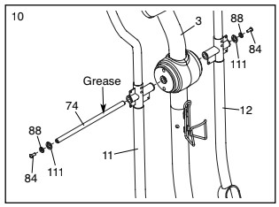
Orient the Left Upper Body Arm (11) as shown, and slide it onto the left end of the Pivot Axle (74). Slide the Right Upper Body Arm (12) onto the right end of the Pivot Axle.
Tighten an M8 x 23mm Button Screw (84) with an M8 Washer (88) and a Wave Washer (111) into each end of the Pivot Axle (74). Make sure that the Wave Washers are on the ends of the Pivot Axle.
- Hold the Left Front Handlebar Cover (18) and the 11 Left Rear Handlebar Cover (19) around the Left Upper Body Arm (11). Attach the Handlebar Covers with three M4 x 32mm Round Head Screws (105).
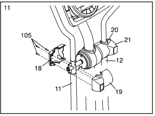
Attach the Right Front Handlebar Cover (20) and the Right Rear Handlebar Cover (21) in the same way.
- Identify the Left Pedal (13) and the Left Pedal Leg 12 (14), which are marked with stickers.
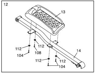
Attach the Left Pedal (13) to the Left Pedal Leg (14) with an M4 x 45mm Screw (108), three M4 x 14mm Screws (104), and four Star Washers (112).
Attach the Right Pedal (not shown) to the Right Pedal Leg (not shown) in the same way.
- Apply a thin film of grease to one of the Pedal Leg Axles (82) and to the faces of the two Pedal Leg Bushings (33) in the Left Pedal Leg (14).
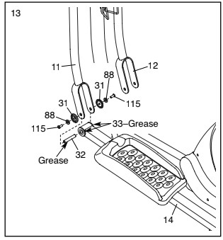
Next, slide an M8 Washer (88) and a Pedal Leg Cover (31) onto an M8 x 23mm Shoulder Screw (115), and turn the Shoulder Screw a few turns into the Pedal Leg Axle (32).
While another person holds the front end of the Left Pedal Leg (14) inside of the bracket on the Left Upper Body Arm (11), insert the Pedal Leg Axle (32) into both parts. Next, slide an M8 Washer (88) and a Pedal Leg Cover (31) onto another M8 x 23mm Shoulder Screw (115), and turn the Shoulder Screw a few turns into the Pedal Leg Axle. Tighten both Shoulder Screws.
Repeat this step on the other side of the elliptical exerciser.
- Lift the latch on the underside of the Left Pedal Leg(14), and set the Left Pedal Leg on the left Crank Bushing Sleeve (43). Release the lever, and make sure that the Left Pedal Leg is securely connected to the Crank Bushing Sleeve.
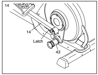
Connect the Right Pedal Leg (not shown) in the same way.
See step 5. Tighten the M8 x 69mm Button Bolt (80) and the two M8 x 23mm Button Screws (84).
- Make sure that all parts of the elliptical exerciser are properly tightened. Note: Some hardware may be left over after assembly is completed. To protect the floor or carpet from damage, place a mat under the elliptical exerciser.
HOW TO USE THE ELLIPTICAL EXERCISER
HOW TO FOLD AND UNFOLD THE ELLIPTICAL EXERCISER
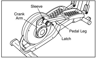
When the elliptical exerciser is not in use, the frame can be folded out of the way. First, lift the latch under each pedal leg, and lift the pedal legs off the sleeves on the crank arms.
Next, raise the pedal legs until they touch the magnets on the upper body arms; the magnets will hold the pedal legs in place. Then, hold the handle and lift the frame until it locks in a vertical position.
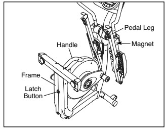
To use the elliptical exerciser, first hold the handle, press the latch button, and lower the frame.
Next, pull the pedal legs off the magnets on the upper body arms. Then, lift the latches under the pedal legs, and set the pedal legs on the sleeves on the crank arms. Release the latches, and make sure that the pedal legs are securely connected to the crank arms.
HOW TO MOVE THE ELLIPTICAL EXERCISER
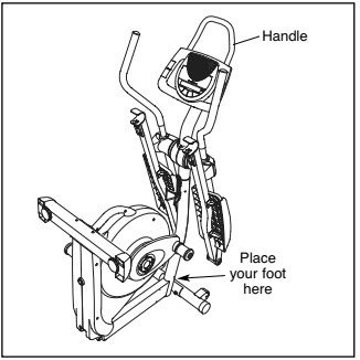
To move the elliptical exerciser, first fold it as described at the left. Next, stand in front of the elliptical exerciser, hold the handle on the console bracket, and place one foot against the center of the front stabilizer. Pull the handle until the elliptical exerciser will roll on the front wheels. Carefully move the elliptical exerciser to the desired position, and then lower it.
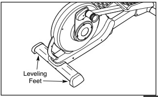
HOW TO LEVEL THE ELLIPTICAL EXERCISER
If the elliptical exerciser rocks slightly on your floor during use, turn one or both of the leveling feet beneath the rear stabilizer until the rocking motion is eliminated.
HOW TO EXERCISE ON THE ELLIPTICAL EXERCISER
To mount the elliptical exerciser, hold the handle and step onto the pedal that is in the lowest position. Next, step onto the other pedal. Push the pedals until they begin to move with a continuous motion. Note: The pedal discs can turn in either direction. It is recommended that you turn the pedal discs in the direction shown by the arrow below; however, for variety, you can turn the pedal discs in the opposite direction.
To dismount the elliptical exerciser, wait until the pedals come to a complete stop. Note: The elliptical exerciser does not have a free wheel; the pedals will continue to move until the flywheel stops. When the pedals are stationary, step off the highest pedal first. Then, step off the lowest pedal.
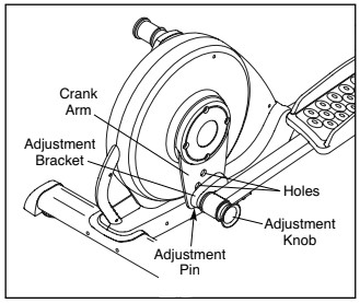
HOW TO ADJUST THE STRIDE OF THE ELLIPTICAL EXERCISER
To adjust the stride of the elliptical exerciser, first pull one of the adjustment knobs until the adjustment bracket can be pivoted freely. Pivot the adjustment bracket until the adjustment knob is aligned with one of the three holes in the crank arm, and gently release the knob. Then, pivot the adjustment bracket back and forth slightly to make sure that the adjustment pin is engaged in one of the three holes in the crank arm.
Adjust the other side of the elliptical exerciser in the same way.
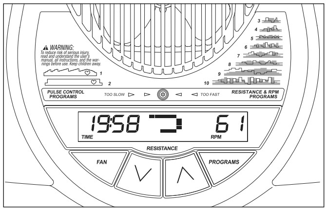
FEATURES OF THE CONSOLE
The advanced console offers an array of features designed to make your workouts more effective and enjoyable.
When the manual mode of the console is selected, you can change the resistance of the pedals with the touch of a button. As you exercise, the console will provide continuous exercise feedback. You can even monitor your heart rate using the handgrip pulse sensor.
The console also offers two pulse control programs and eight resistance & rpm programs. Each pulse control program automatically controls the resistance of the pedals and prompts you to increase or decrease your pedaling pace to keep your heart rate near a target heart rate setting during your workout. Each resistance & rpm program automatically changes the resistance of the pedals and prompts you to vary your pedaling pace as it guides you through an effective workout.
To use the manual mode of the console, follow the steps beginning on page 15. To use a pulse control program, see page 17. To use a resistance & rpm program, see page 19.
Note: If there is a sheet of clear plastic on the face of the console, remove the plastic.
HOW TO USE THE MANUAL MODE
- Press the Resistance decrease button or begin pedaling to turn on the console.
A moment after the console is turned on, the display will light.
- Select the manual mode.
Each time the console is turned on, the manual mode will be selected automatically. If you have selected a program, select the manual mode by pressing the Programs button repeatedly until the display appears as shown below.
- Begin pedaling and change the resistance of the pedals as desired.
As you pedal, change the resistance of the pedals by pressing the Resistance increase and decrease buttons repeatedly. There are ten resistance levels.

Note: After the buttons are pressed, it will take a moment for the pedals to reach the selected resistance level.
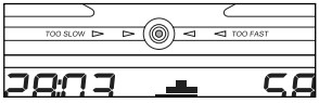
- Monitor your progress with the display.
The left side of the display—The left side of the display will show the elapsed time and the approximate number of calories you have burned.
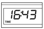
Note: When a preset program is selected (except for pulse program 2), the display will show the time remaining in the program instead of the elapsed time.
The left side of the display will also show your heart rate when you use the handgrip pulse sensor (see step 5 on page 16).
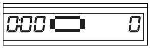
The center of the display—When the manual mode is selected, the center of the display will show a track that represents 640 revolutions. As you exercise, the indicators around the track will appear in succession until the entire track appears. The track will then disappear and the indicators will again begin to appear in succession.
The center of the display will also show the resistance setting of the pedals for a few seconds each time the resistance setting changes.
The right side of the display —The right side of the display will show the distance (total revolutions) you have pedaled and your pedaling pace (revolutions per minute [rpm]).

- Measure your heart rate if desired.
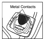
If there are thin sheets of plastic on the metal contacts on the handgrip pulse sensor, peel off the plastic. To measure your heart rate, hold the handgrip pulse sensor, with your palms resting against the metal contacts. Avoid moving your hands or gripping the contacts too tightly.
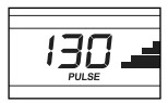
When your pulse is detected, a heart-shaped symbol will flash in the left side of the display each time your heart beats, one or two dashes will appear, and then your heart rate will be shown.
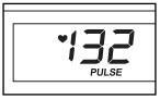
For the most accurate heart rate reading, hold the contacts for at least 15 seconds. Note: If you continue to hold the handgrip pulse sensor, the display will show your heart rate for up to 30 seconds. The display will then show your heart rate along with the other modes.
If your heart rate is not shown, make sure that your hands are positioned as described. Be careful not to move your hands excessively or to squeeze the metal contacts too tightly. For optimal performance, clean the metal contacts using a soft cloth; never use alcohol, abrasives, or chemicals.
- Turn on the fan if desired.
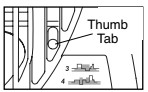
To turn on the fan at low speed, press the Fan button. To turn on the fan at high speed, press the button a second time. To turn off the fan, press the button a third time. Note: If the pedals are not moved for a few minutes, the fan will automatically turn off to conserve the batteries.
Pivot the thumb tab on the right side of the fan to adjust the angle of the fan.
- When you are finished exercising, the console will automatically turn off.
If the pedals are not moved for several seconds, a tone will sound and the console will pause.
If the pedals are not moved for about five minutes, the console will turn off and the display will be reset.
HOW TO USE A PULSE CONTROL PROGRAM
- Press the Resistance decrease button or begin pedaling to turn on the console.
A moment after the console is turned on, the display will light.
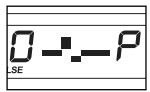
- Select one of the pulse control programs.
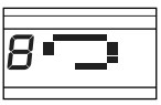
Press the Programs button repeatedly until “P 1” or “P 2” appears in the right side of the display.

If pulse control program 1 is selected, a profile of the target heart rate settings of the program will scroll across the center of the display.
If pulse control program 2 is selected, a pulse symbol will appear in the center of the display. Each time a heartbeat is detected while you are using the handgrip pulse sensor, the pulse symbol will reappear.
- Enter a target heart rate setting.
If pulse control program 1 is selected, the maximum target heart rate setting of the program will flash in the display. If desired, press the Resistance increase and decrease buttons to change the maximum target heart rate setting (see EXERCISE INTENSITY on page 21). If you change the maximum target heart rate setting, the intensity level of the entire program will change.
If pulse control program 2 is selected, the target heart rate setting for the program will flash in the display. If desired, press the Resistance increase and decrease buttons to change the target heart rate setting (see EXERCISE INTENSITY).
- Hold the handgrip pulse sensor.
It is not necessary to hold the handgrip pulse sensor continuously during a pulse control program; however, you should hold the handgrip pulse sensor frequently for the program to operate properly.
Each time you hold the handgrip pulse sensor, keep your hands on the metal contacts for at least 30 seconds.
- Begin pedaling to start the program.
Pulse control program 1 is divided into 30 one-minute segments. One target heart rate setting is programmed for each segment. Note: The same target heart rate setting may be programmed for two or more consecutive segments.
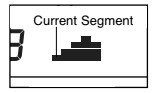
The target heart rate setting for the first segment will be shown in the flashing Current Segment column in the center of the display.
The target heart rate settings for the next four segments will be shown in the columns to the right.
When only three seconds remain in the first segment of the program, both the Current Segment column and the column to the right will flash, a series of tones will sound, and all target heart rate settings will move one column to the left. The target heart rate setting for the second segment will then be shown in the flashing Current Segment column.
Pulse control program 2 is divided into 40 one-minute segments. The same target heart rate setting is programmed for all segments. Note: For a shorter workout, stop exercising or select a different program before the program ends.
During both pulse control programs, the console will regularly compare your heart rate to the target heart rate setting. If your heart rate is too far below or above the target heart rate setting, the resistance of the pedals will automatically increase or decrease to bring your heart rate closer to the target heart rate setting.
After the first minute of the program, the Pace Coach will prompt you to maintain a consistent pedaling pace. When one of the “Too Slow” arrows lights, increase your pace. When the one of the “Too Fast” arrows lights, decrease your pace. When the center indicator lights, maintain your current pace.
IMPORTANT: The target heart rate settings are intended only to provide motivation. Your actual heart rate may be slower than the target heart rate settings. Make sure to exercise at a pace that is comfortable for you.
Note: During the program, you can manually over-ride the resistance setting for the current segment, if desired, by pressing the increase and decrease buttons. However, when the console compares your heart rate to the target heart rate setting, the resistance of the pedals may automatically increase or decrease to bring your heart rate closer to the target heart rate setting.
If you stop pedaling for several seconds, a tone will sound and the program will pause. To restart the program, simply resume pedaling.
- Monitor your progress with the display.
- Turn on the fan if desired.
- When you are finished exercising, the console will automatically turn off.
HOW TO USE A RESISTANCE & RPM PROGRAM
- Press the Resistance decrease button or begin pedaling to turn on the console.
A moment after the console is turned on, the display will light.
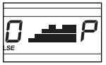
- Select one of the resistance & rpm programs.
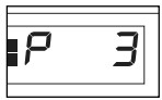
Press the Programs button repeatedly until “P 3,” P 4,” P 5,” *p6,” “P 7,” P 8,” “P9,” or “P10” appears in the right side of the display. When a resistance & rpm program is selected, a profile of the resistance settings of the program will scroll across the center of the display. The left side of the display will show how long the program will last.
- Begin pedaling to start the program.
Each program is divided into several one-minute segments. One resistance setting and one pace setting are programmed for each segment. Note: The same resistance setting and/or pace setting may be programmed for two or more consecutive segments.
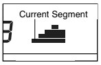
The resistance setting for the first segment will be shown in the flashing Current Segment column in the center of the display.
(Note: The pace settings are not shown in the display.) The resistance settings for the next four segments will be shown in the columns to the right.
As you exercise, the Pace Coach will help you to keep your pedaling pace near the pace setting for the current segment. When one of the “Too Slow” arrows lights, increase your pace. When the one of the “Too Fast” arrows lights, decrease your pace. When the center indicator lights, maintain your current pace.
IMPORTANT: The pace settings are intended only to provide motivation. Your actual pace may be slower than the pace settings. Make sure to exercise at a pace that is comfortable for you.
When only three seconds remain in the first segment of the program, both the Current Segment column and the column to the right will flash, a series of tones will sound, and ail resistance settings will move one column to the left. The resistance setting for the second segment will then be shown in the flashing Current Segment column, and the resistance of the pedals will change to the resistance setting for the second segment. Note: If all of the indicators in the Current Segment column are lit after the resistance settings have moved to the left, the resistance settings may move downward so only the highest indicators appear in the matrix.
The program will continue until the resistance setting for the last segment is shown in the Current Segment column and the last segment ends.
Note: During the program, you can override the resistance setting for the current segment, if desired, by pressing the increase or decrease button. However, when the next segment begins, the resistance will change if a different resistance setting is programmed for the next segment.
If you stop pedaling for several seconds, a tone will sound and the program will pause. To restart the program, simply resume pedaling.
- Monitor your progress with the display.
- Measure your heart rate if desired.
- Turn on the fan if desired.
- When you are finished exercising, the console will automatically turn off.
MAINTENANCE AND TROUBLESHOOTING
Inspect and tighten all parts of the elliptical exerciser regularly. Replace any worn parts immediately.
To clean the elliptical exerciser, use a damp cloth and a small amount of mild soap. IMPORTANT: To avoid damage to the console, keep liquids away from the console and keep the console out of direct sunlight.
BATTERY REPLACEMENT
If the console display becomes dim, the batteries should be replaced; most console problems are the result of low batteries. See assembly step 7 for replacement instructions.
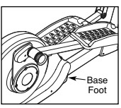
HOW TO ELIMINATE FLEXING IN THE CENTER OF THE ELLIPTICAL EXERCISER
If the elliptical exerciser flexes in the center during use, turn the base foot until the flexing is eliminated.
HOW TO LEVEL THE ELLIPTICAL EXERCISER
If the elliptical exerciser rocks slightly on your floor during use, see HOW TO LEVEL THE ELLIPTICAL EXERCISER
HANDGRIP PULSE SENSOR TROUBLESHOOTING
- Avoid moving your hands while using the handgrip pulse sensor. Excessive movement may interfere with heart rate readings.
- Do not hold the metal contacts too tightly; doing so may interfere with heart rate readings.
- For the most accurate heart rate reading, hold the metal contacts for about 30 seconds.
- For optimal performance of the handgrip pulse sensor, keep the metal contacts clean. The contacts can be cleaned with a soft cloth—never use alcohol, abrasives, or chemicals.
EXERCISE GUIDELINES
WARNING: Before beginning this or any exercise program, consult your physician. This is especially important for persons over the age of 35 or persons with pre-existing health problems.
The pulse sensor is not a medical device. Various factors may affect the accuracy of heart rate readings. The pulse sensor is intended only as an exercise aid in determining heart rate trends in general.
These guidelines will help you to plan your exercise program. For detailed exercise information, obtain a reputable book or consult your physician. Remember, proper nutrition and adequate rest are essential for successful results.
EXERCISE INTENSITY
Whether your goal is to burn fat or to strengthen your cardiovascular system, exercising at the proper intensity is the key to achieving results. You can use your heart rate as a guide to find the proper intensity level.
The chart below shows recommended heart rates for fat burning and aerobic exercise.
165 155 145 140 130 125 115 145 138 130 125 118 110 103 125 120 115 110 105 95 90 | [ image ] |
| 20 30 40 50 60 70 80 |
To find the proper intensity level, find your age at the bottom of the chart (ages are rounded off to the nearest ten years). The three numbers listed above your age define your “training zone.” The lowest number is the heart rate for fat burning, the middle number is the heart rate for maximum fat burning, and the highest number is the heart rate for aerobic exercise.
Burning Fat—To burn fat effectively, you must exercise at a low intensity level for a sustained period of time. During the first few minutes of exercise, your body uses carbohydrate calories for energy. Only after the first few minutes of exercise does your body begin to use stored fat calories for energy. If your goal is to burn fat, adjust the intensity of your exercise until your heart rate is near the lowest number in your training zone. For maximum fat burning, exercise with your heart rate near the middle number in your training zone.
Aerobic Exercise—If your goal is to strengthen your cardiovascular system, you must perform aerobic exercise, which is activity that requires large amounts of oxygen for prolonged periods of time. For aerobic exercise, adjust the intensity of your exercise until your heart rate is near the highest number in your training zone.
WORKOUT GUIDELINES
Warming up—Start with 5 to 10 minutes of stretching and light exercise. A warm-up increases your body temperature, heart rate, and circulation in preparation for exercise.
Training Zone Exercise—Exercise for 20 to 30 minutes with your heart rate in your training zone. (During the first few weeks of your exercise program, do not keep your heart rate in your training zone for longer than 20 minutes.) Breathe regularly and deeply as you exercise—never hold your breath.
Cooling down—Finish with 5 to 10 minutes of stretching. Stretching increases the flexibility of your muscles and helps to prevent post-exercise problems.
EXERCISE FREQUENCY
To maintain or improve your condition, complete three workouts each week, with at least one day of rest between workouts. After a few months of regular exercise, you may complete up to five workouts each week, if desired. Remember, the key to success is to make exercise a regular and enjoyable part of your everyday life.
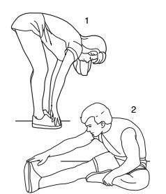
SUGGESTED STRETCHES
The correct form for several basic stretches is shown at the right. Move slowly as you stretch—never bounce.
1. Toe Touch Stretch
Stand with your knees bent slightly and slowly bend forward from your hips. Allow your back and shoulders to relax as you reach down toward your toes as far as possible. Hold for 15 counts, then relax. Repeat 3 times. Stretches: Hamstrings, back of knees and back.
2. Hamstring Stretch
Sit with one leg extended. Bring the sole of the opposite foot toward you and rest it against the inner thigh of your extended leg. Reach toward your toes as far as possible. Hold for 15 counts, then relax. Repeat 3 times for each leg. Stretches: Hamstrings, lower back and groin.
3. Calf/Achilles Stretch
With one leg in front of the other, reach forward and place your hands against a wall. Keep your back leg straight and your back foot flat on the floor. Bend your front leg, lean forward and move your hips toward the wall. Hold for 15 counts, then relax. Repeat 3 times for each leg. To cause further stretching of the Achilles tendons, bend your back leg as well. Stretches: Calves, Achilles tendons and ankles.
4. Quadriceps Stretch
With one hand against a wall for balance, reach back and grasp one foot with your other hand. Bring your heel as close to your buttocks as possible. Hold for 15 counts, then relax. Repeat 3 times for each leg. Stretches: Quadriceps and hip muscles.
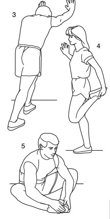
5. Inner Thigh Stretch
Sit with the soles of your feet together and your knees outward. Pull your feet toward your groin area as far as possible. Hold for 15 counts, then relax. Repeat 3 times. Stretches: Quadriceps and hip muscles.
PART LIST—Model No. NTEL7996.0
Key No. Qty. Description
| Key No. | Qty. | Description |
| 1 | 1 | Base |
| 2 | 1 | Frame |
| 3 | 1 | Upright |
4 | 1 | Console Bracket |
5 | 1 | Console |
6 | 1 | Front Stabilizer |
7 | 1 | Rear Stabilizer |
8 | 1 | Left Handlebar |
9 | 1 | Right Handlebar |
10 | 2 | Handlebar Endcap Left Pedal |
11 | 1 | Left Upper Body Arm |
12 | 1 | Right Upper Body Arm |
13 | 1 | Left Pedal |
14 | 1 | Left Pedal Leg |
15 | 1 | Right Pedal |
16 | 1 | Right Pedal Leg |
17 | 2 | Upright Cover |
18 | 1 | Left Front Handlebar Cover |
19 | 1 | Left Rear Handlebar Cover |
20 | 1 | Right Front Handlebar Cover |
21 | 1 | Right Rear Handlebar Cover |
22 | 1 | Water Bottle Holder |
23 | 2 | Front Stabilizer Endcap |
24 | 2 | Rear Stabilizer Endcap |
25 | 2 | Wheel |
26 | 1 | Base Foot |
27 | 2 | Leveling Foot |
28 | 1 | Left Side Shield |
29 | 1 | Right Side Shield |
30 | 6 | Upper Body Bushing |
31 | 4 | Pedal Leg Cover |
32 | 2 | Pedal Leg Axle |
33 | 4 | Pedal Leg Bushing |
34 | 1 | Base Axle |
35 | 2 | Base Bushing |
36 | 1 | Left Crank Arm |
37 | 2 | Adjustment Arm Cover Pulley |
38 | 2 | Crank Hub |
39 | 1 | Pulley Spacer Crank Hub |
40 | 1 | Pulley |
41 | 2 | Adjustment Arm |
42 | 4 | Crank Bushing |
43 | 2 | Crank Bushing Sleeve |
44 | 2 | Crank Bearing Set |
45 | 1 | Crank |
46 | 1 | Crank Spacer |
47 | 2 | Crank Snap Ring |
48 | 1 | Upper Wire Harness |
49 | 1 | Lower Wire Harness |
50 | 1 | Reed Switch / Wire |
51 | 1 | Belt |
52 | 1 | Flywheel |
53 | 1 | “C” Magnet |
54 | 1 | Pillow Block |
55 | 1 | Magnet |
56 | 1 | Spring |
57 | 1 | Idler |
58 | 1 | Idler Bracket |
59 | 1 | Clamp |
60 | 1 | Reed Switch Bracket |
61 | 1 | Base Pin |
62 | 2 | Latch Bracket Spacer |
63 | 2 | Hair Pin |
64 | 1 | Latch Bracket |
65 | 1 | Pivot Bracket |
66 | 2 | Pivot Bracket Spacer |
67 | 1 | Frame Pin |
68 | 1 | Latch Button |
69 | 1 | Roll Pin |
70 | 1 | Motor |
71 | 1 | Resistance Cable Pulley |
72 | 1 | Resistance Cable Set |
73 | 2 | Foam Grip |
74 | 1 | Pivot Axle |
75 | 2 | Hub Cover |
76 | 2 | Adjustment Knob |
77 | 4 | M6 x 20mm Button Screw |
78 | 4 | M8 x 43mm Button Bolt |
79 | 7 | M8 Jam Nut |
80 | 1 | M8 x 69mm Button Bolt |
81 | 2 | M10 Nylon Locknut |
82 | 2 | M10 x 82mm Button Screw |
83 | 2 | M10 x 127mm Button Screw |
84 | 8 | M8 x 23mm Button Screw |
85 | 1 | M6 x 10mm Button Screw |
86 | 2 | Crank Screw |
87 | 8 | Hub Screw |
88 | 8 | M8 Washer |
89 | 2 | M10 x 60mm Button Screw |
90 | 3 | M8 Split Washer |
91 | 1 | Flywheel Spacer |
92 | 1 | Flywheel Washer |
93 | 1 | Flywheel Snap Ring |
94 | 4 | Pillow Block Screw |
95 | 1 | Stop Screw |
96 | 1 | M8 x 35mm Screw |
97 | 1 | “E” Clip |
98 | 4 | Pulley Screw |
99 | 2 | Adjustment Pin |
100 | 2 | M4 x 25mm Screw |
101 | 14 | M4 x 16mm Round Head Screw |
102 | 4 | Motor Washer |
103 | 13 | M4 x 16mm Screw |
| 104 | 8 | M4 x 14mm Screw |
105 | 6 | M4 x 32mm Round Head Screw |
106 | 2 | Adjustment Spring |
107 | 4 | M4 x 12mm Screw |
108 | 2 | M4 x 45mm Screw |
109 | 2 | Large Snap Ring |
110 | 2 | M8 Small Washer |
111 | 2 | Wave Washer |
112 | 8 | Star Washer |
113 | 1 | M10 Washer |
114 | 1 | M6 Nut |
115 | 4 | M8 x 23mm Shoulder Screw |
116 | 8 | M8 x 15mm Button Screw |
117 | 2 | Large Wave Washer |
118 | 1 | Left Stabilizer Cover |
119 | 1 | Right Stabilizer Cover |
120 | 2 | M4 x 12mm Round Head Screw |
121 | 2 | M8 Large Washer |
122 | 2 | Middle Wave Washer |
123 | 1 | Right Crank Arm |
124 | 2 | Flywheel Bracket |
* | —- | Hex Key |
* | —- | Grease |
* | —- | User’s Manual |
Note: Specifications are subject to change without notice. See the back cover of this manual for information about ordering replacement parts. *These parts are not illustrated.
EXPLODED DRAWING A—Model No. NTEL7996.0 RO308A
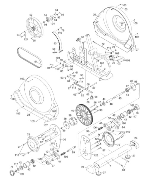
EXPLODED DRAWING B—Model No. NTEL7996.0 RO308A
ORDERING REPLACEMENT PARTS
To order replacement parts, see the front cover of this manual. To help us assist you, please be prepared to provide the following information when contacting us:
- the model number and serial number of the product (see the front cover of this manual)
- the name of the product (see the front cover of this manual)
- the key number and description of the replacement part(s) (see the PART LIST and the EXPLODED DRAWING near the end of this manual)
LIMITED WARRANTY
ICON Health & Fitness, Inc. (ICON) warrants this product to be free from defects in workmanship and material, under normal use and service conditions, for a period of one (1) year from the date of purchase. This warranty extends only to the original purchaser. ICON’s obligation under this warranty is limited to replacing or repairing, at ICON’s option, the product through one of its authorized service centers. All repairs for which warranty claims are made must be pre-authorized by ICON. If the product is shipped to a service center, freight charges to and from the service center will be the customer’s responsibility. For in-home service, the customer will be responsible for a minimal trip charge. This warranty does not extend to any product or damage to a product caused by or attributable to freight damage, abuse, misuse, improper or abnormal usage or repairs not provided by an ICON authorized service center; products used for commercial or rental purposes; or products used as store display models. No other warranty beyond that specifically set forth above is authorized by ICON.
ICON is not responsible or liable for indirect, special or consequential damages arising out of or in connection with the use or performance of the product or damages with respect to any economic loss, loss of property, loss of revenues or profits, loss of enjoyment or use, costs of removal or installation or other consequential damages of whatsoever nature. Some states do not allow the exclusion or limitation of incidental or consequential damages. Accordingly, the above limitation may not apply to you.
The warranty extended hereunder is in lieu of any and all other warranties and any implied warranties of merchantability or fitness for a particular purpose is limited in its scope and duration to the terms set forth herein. Some states do not allow limitations on how long an implied warranty lasts. Accordingly, the above limitation may not apply to you.
This warranty gives you specific legal rights. You may also have other rights which vary from state to state.
ICON HEALTH & FITNESS, INC., 1500 S. 1000 W., LOGAN, UT 84321-9813
You can download the PDF version of NordicTrack CX 1000 Space Saver User’s Manual (Model No. NTEL7996.0) here.