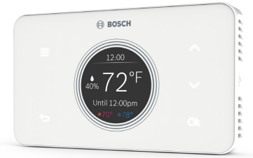
Meet the Bosch Connected Control (BCC50 Thermostat)
The Bosch Connected Control BCC50 Thermostat is compatible with the majority of 24VAC heating and cooling equipment to help you save energy and money. Easily control your home’s temperature from the intuitive interface using the 5 back-lit touch buttons, the Bosch Connected Control smartphone app or your voice with the Bosch Connected Control Alexa Smart Home Skill and your Alexa-enabled smart devices or with Google Assistant.


Compatibility
- A C-wire (common wire) is required to power the unit Two wire systems are not supported. If a C-wire is not readily available, we recommend you seek professional support from your local contractor.
- The Bosch Connected Control BCC50 Thermostat works with most 24VAC systems, including gas, oil, propane, electric, forced air, variable speed, heat pump and radiant.
The thermostat cannot support
- Line voltage thermostats
- Electric baseboard heaters
- Proprietary communicating thermostats
- Millivolt systems
- Remote sensors
Professional installation is recommended for the following systems
- Dual Fuel systems (Heat Pump combined with a Furnace)
- Whole-home humidifiers and dehumidifiers
Are you unsure of your system compatibility or how to install your thermostat and need help?
- Self-support videos can be found on our website at: BoschHeatingAndCooling.com/BCC50
- Contact our support team at 1-800-283-3787
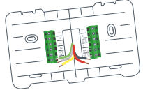
Installation Overview
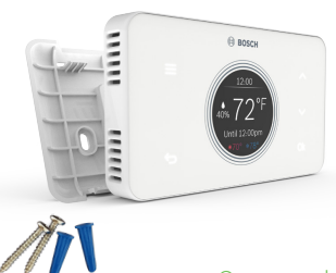
Included in the box
- Thermostat
- Wall Plate
- Screws & Wall Anchors
- Installation Guide and User Manual
- Wire Labels
Tools you will need
Small flathead screwdriver
(for fastening the Wall Plate wire terminals)
Medium Phillips screwdriver
(for attaching the Wall Plate to the wall)
Smartphone
(for taking pictures of the existing wiring)
Bosch Connected Control smartphone app
(for configuring the thermostat settings)
Tools you may need
- Needle-Nose Pliers (for pulling wires from the wall)
- Drill with 7/32” Drill Bit (for mounting wall anchors)
- Wire Stripper (for cutting and stripping wires)
- Multimeter (for testing circuit continuity)
- Pen or Pencil (for preventing wires from falling into the wall)
Once you have everything you need, let’s get started!
Thermostat Installation
Step 1: Turn OFF power
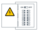
Turn off all power to your HVAC (Heating, Ventilation, and Air Conditioning) system by using the master equipment switch or circuit breaker box.
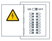
WARNING: Failure to turn off the power may result in electrical shock and/or damage to the equipment.
Confirm that your system is off
Try to adjust the temperature on your old thermostat. If you don’t hear the system turn on within 5 minutes, air does not come out from the vents or the old thermostat does not even power on, then you have successfully turned off the power to your system.
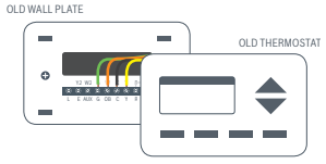
Step 2: Remove the old thermostat from the old wall plate
Step 3: Make sure your old thermostat
Does Not Contain Line Voltage Wiring
If you see any of these wire nuts, unfortunately the BCC50 will not work with your system. If you are unsure or would like to discuss your options, please contact a professional or our support line: 1-800-283-3787.
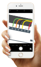
Step 4: Take a picture of the existing wiring
Make sure that you can clearly read the terminal labels and see which wires are connected to which terminal from your photo. You will need to reference this
photo later during the initial setup.
Note: You can also use the wire labels we have provided you to correctly label each wire based on the terminal where it is connected.
Step 5: Confirm you have a C-wire connected to your old thermostat wall plate
If you do not have a C-wire connected to your old thermostat, please contact a professional or our support line for further assistance to determine if the BCC50
Thermostat is compatible with your system.
Step 6: Disconnect the wires from the old thermostat and remove the wall plate using a screwdriver
Some thermostats will also require you to use a screwdriver to disconnect the wires. After the wires are disconnected and the wall plate removed, we recommend wrapping a pen or pencil around the wires to prevent them from falling back into the wall.
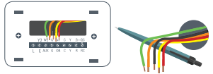
Step 7: Pull thermostat wires through the hole in the center of the BCC50 wall plate and mark the location of the mounting screws
It is recommended to use the BCC50 Wall Plate as a reference guide to mark the mounting holes and ensure that all holes and unpainted surfaces are covered.
Note: If the new Wall Plate does not cover up any holes or unpainted spaces left by your old thermostat, use this opportunity to patch any holes and paint.
Thermostat Installation
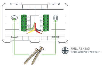
Step 8: Drill and insert wall anchors (if necessary)
Drill two 7/32” holes where you marked the location of the mounting screws and then insert the wall anchors provided into these mounting holes.
Check if the wall plate is level and insert screws
Make sure your new BCC50 wall plate is level and insert the included screws from the package and mount your new wall plate to the wall using a Phillips head screw driver.
LEVEL
Step 9: Insert each wire into the corresponding terminal and close each terminal using a flat head screw driver
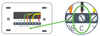
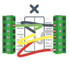
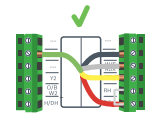
Use the image you took with your smartphone of your old thermostat wiring or the wire labels as a reference for where to place each wire. Be sure that you insert each wire, one by one, and then. immediately close the terminal and confirm that the wire is secure inside the terminal before moving to the next wire. Repeat this process for each wire to be installed. If you are unsure of the terminal names on the BCC50 Wall Plate, refer to BCC50 Terminal Key.
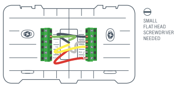
BCC50 Terminal
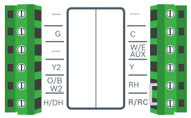
BCC50 Terminal Key
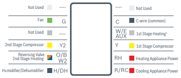
Note: The color of your wires may not be the same as shown (1)Emergency Heat and Auxiliary Heat activated at W/E/AUX.
Step 10: After all wires are securely connected, gently push any excess wires back into the hole in the wall
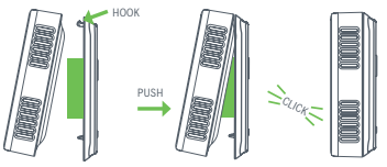
Step 11: Attach the BCC50 thermostat to the BCC50 wall plate
Step 12: Turn ON the power to your HVAC by using the master equipment switch or circuit breaker box
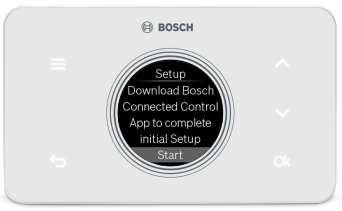
The thermostat will power on and display a Bosch logo and loading bar.
Note: After loading completes, the thermostat will display the following screen:
Step 13
Great Job, The Hard Parts Over!
Next get your smartphone and visit your app store. Download the Bosch Connected Control app to setup your new BCC50
Your BCC50 Thermostat is not yet configured to your home’s HVAC system. Go to the App Store or Google Play to download the app, create an account and finish configuring your system.
Three ways to download the Connected Control App:
- In the App Store or Google Play, search “Bosch Connected Control” or “BCC50” and then download the app.
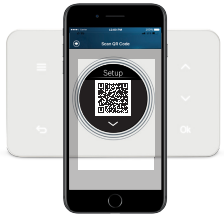
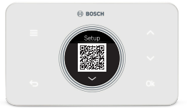
- Visit www.bosch-climate.us/bcc50 or scan QR code below. Click the links for the app in the Download App section.
Initial Setup
User Account Setup
- After downloading the Bosch Connected Control app, open the app on your smartphone and click the Register button to create a new account.
- Read and accept the Terms and Conditions and Privacy policy, and press continue in the top right hand corner.
- Follow the on-screen instructions to create your account and then press OK at the bottom of the screen.
- After a successful registration, you can use your newly created user ID and password to log into your account.
Note: You will also receive a confirmation email from the Bosch Team confirming your account creation.
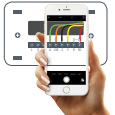
Add Device
- After signing into your account, click the plus sign (+) in the top right hand corner to add a new device.
- On the next screen, click the device you would like to add, in this case the BCC50.
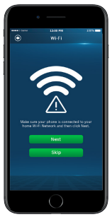
- Return to your thermostat and click Ok to initiate the Initial Setup. Return to your app, and follow the on-screen instructions to connect the BCC50 Thermostat to your home’s Wi-Fi network.
Note: If you skip this step, you will be required to repeat the initial setup in the future to make any changes or adjustments to the thermostat settings.
- After you have successfully connected to your home’s Wi-Fi Network, follow the on-screen instructions to name your thermostat and connect your smartphone directly to the thermostat to complete the initial setup.
- Use the up and down arrows on your thermostat to change between Automatic Entry and Manual Entry.
- If your thermostat is unable to connect to the app, follow the on-screen instructions.
- After the Initial Setup, the Thermostat will say ‘You are connected to the app. Please follow the guided setup process in your app’
Note: You can use the QR code scanner by clicking the QR icon in the Device SSID field to automatically enter the Device SSID and Device password by scanning the QR code on your thermostat. You can also manually enter the information into the app using the information provided on the thermostat.
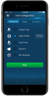
Unit Configuration
Select your Heat Type according to the heating appliance located in your home. Below is a list of helpful tips that may guide you to selecting the correct option for your home.
Note: If you are unsure of which option to select, contact your local contractor or our support line: 1-800-283-3787.
If you have a furnace
- Select Fossil Fuel and click the setup button to the right
- Then select Appliance or Thermostat depending on your personal preferences for fan control.
- Click Next at the bottom of the screen to continue.
If you have a boiler
- Select Fossil Fuel and click the setup button to the right
- Then select Appliance
- Click Next at the bottom of the screen to continue.
If you have a heat pump
- Select Heat Pump and click the setup button to the right
- Then follow the on-screen instructions.
- Click Next at the bottom of the screen to continue.
If you have a dual fuel system
- Select Dual Fuel and click the setup button to the right
- Then follow the on-screen instructions to configure the fossil fuel heating appliance settings
- Click Next at the bottom of the screen to continue. Then follow the on-screen instructions to configure the heat pump heating appliance settings.
- Use the Balance Point to set the outdoor temperature value the thermostat will use to switch between your heat pump and fossil fuel appliance. Above this value, your thermostat will use your heat pump to heat your home and below this value, your thermostat will use your fossil fuel heating appliance.
- Use the Change over Delay to set the time the system will be off when changing between heat pump and fossil fuel heating sources. This delay allows for the coil to cool before switching between heating appliances.
Note: In a dual fuel system, the BCC50 automatically enables auxiliary heating and emergency heating using the fossil fuel heating appliance.
Note: In a dual fuel system, the BCC50 will stage up from heat pump to fossil fuel following the stage settings, which can be modified in Advanced Settings > Installer Access > by using the ST Action Code.
6.Click Next at the bottom of the screen to continue.
If you have an electric system: Select Electric and click Next at the bottom of the screen to continue.
If you have no heating appliance: Select No Heating and click Next at the bottom of the screen to continue.
Select your stage configuration: According to the heating and cooling appliances you have in your home and then click Next.
If you have a whole home humidifier or dehumidifier accessory wired to your thermostat, select the type of accessory you have in your home; otherwise, click None and then click Next.
Note: Professional installation is recommended for humidifiers and dehumidifiers.
If you have a Humidifier:
- Select Humidifier and click the setup button to the right.
- Then select Evaporative or Steam following the on-screen instructions.
- Click Next at the bottom of the screen to continue.
If you have a Dehumidifier:
- Select Humidifier and click the setup button to the right.
- Then select Evaporative or Steam following the on-screen instructions.
- Click Next at the bottom of the screen to continue.
If you have a Dehumidifier:
- Select Dehumidifier and click the setup button to the right.
- Then enabled or disabled Cool to Dehumidify following the on-screen instructions.
- Click Next at the bottom of the screen to continue.
Date & Time
Follow the on-screen instructions to set the date and time of BCC50 Thermostat and then click Next.
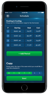
Schedule
- Choose the schedule you would like to modify or click No Schedule if you do not wish to set up a schedule at this time, and click Next.
Note: Home is the default schedule for your BCC50. If you wish to add a different schedule, click the plus (+) button in the top right hand corner of the screen.
- To set up your periods for the day, click on the Start Time bubble of the period and use the scroll wheel to set the start time of the first period of the day.
- Next, click the Heat bubble and use the scroll wheel to set the heating setpoint for the first period of the day.
- Then, click the Cool bubble and use the scroll wheel to set the cooling setpoint for the first period of the day.
Note: There is a 5 degree deadband required between heating and cooling setpoints to prevent your equipment from short cycling.
- If you want to add more periods, then click add period button and repeat the above 3 steps until you have set all your periods for the day.
Note: You are allowed a maximum of 8 periods per day.
- If you want to delete a period, swipe left on the period and click delete.
- After you have set up one day of the week, use the Copy section to mirror the same daily schedule to other days of the week by clicking on the days you would like to copy that daily set of periods. Then click next.
Note: If you have not copied your schedule to all 7 days of the week, you will be required to repeat the above steps until you have set a schedule for everyday of the week.
Review
Review your BCC50’s Initial Setup configuration and click Complete if you are happy with the setup. If you would like to change any of the settings, click on the section you would like to change to be brought back to that section of the Initial Setup.
Congratulations! You have finished the installation and setup of your BCC50 Thermostat. Thank you for choosing Bosch and enjoy the savings and comfort
of owning your Bosch Connected Control thermostat!
Advanced Settings
Advanced Settings allow HVAC professionals the ability to modify specific thermostat settings for better control of the heating and cooling appliance(s). In order to access the Advanced Settings of the BCC50 Thermostat, your thermostat must be connected to Wi-Fi. The Advanced Settings section is accessible from the Menu of the BCC50 smartphone app.
Heating & Cooling
- To access the Heating and Cooling, click Advanced Settings, and enter the Professional Access Code
- Click on a setting and use the scroll wheel to modify the default value. From this menu you can adjust:
| TITLE | Default | Max | Min | Description |
| Fan Delay On | 15 Seconds | 120 Seconds | 0 Seconds | The fan’s lag time after the heating or cooling call is initiated when in Fossil Fuel, Heat Pump, or Cooling operation. |
| Fan Delay On Elec | 0 Seconds | 5 Seconds | 0 Seconds | The fan’s lag time after the heating or cooling call is initiated when in Electric, Auxiliary, or Emergency operation. |
| Fan Delay Off | 60 Seconds | 120 Seconds | 30 Seconds | The fan’s lag time after the heating or cooling call is terminated. |
| Min. Run Time | 5 Minutes | Stage Delay | 3 Minutes | The minimum amount of time the system will cycle upon engagement. |
| Anti Short Cycle | 5 Minutes | 5 Minutes | 0 Minutes | The Anti Short Cycle (ASC) timer represents the minimum amount of time the system will remain off upon stage down engagement. |
| Cycle Time | 180 Seconds | 300 Seconds | 60 Seconds | Time delay between active heating and cooling transition |
| Zero Energy Band Heating | 1° F/ 0.5° C | 2° F/ 1° C | 0.5° F/ 0.3° C | A temperature range between the current temperature and the heating set point, where heating is not engaged (also called deadband). |
| Zero Energy Band Cooling | 1° F/ 0.5° C | 2° F/ 1° C | 0.5° F/ 0.3° C | A temperature range between the current temperature and the cooling set point, where cooling is not engaged (also called deadband). |
Installer Access
- To access the Installer Access, click Advanced Settings, enter the Professional Access Code and click Installer
- Enter any one of the Action Codes in parenthesis below to gain access to that specific setting:
Humidity Calibration (HC)
Ability to adjust humidity readings to improve sensor accuracy as the thermostat nears the end of its lifecycle after years of use.
Relative Humidity Hysteresis (HSD)
A humidity range between the current humidity and humidity set point, where the humidifier or dehumidifier is not engaged (also called a dead band)
Initial Setup (IS)
Use this code to repeat the initial setup process.
Sensor Calibration (SC)
Ability to adjust temperature readings to improve sensor accuracy as the thermostat nears the end of its lifecycle after years of use.
Sensitivity Level (SS)
Ability to adjust how sensitive your thermostat sensor is to changes in the air temperature. The lower the level, the more your system cycles to maintain the setpoint.
Staging (ST)
Ability to adjust 3 configuration options for custom stage up and stage down control. Refer to next page.
Unit Configuration (UC)
Use this code to repeat the unit configuration process.
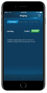
Enables staging logic that will not cycle between stages until the setpoint is met.
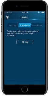
Set the time delay between the stage up logic for non-latching, multi stage equipment.
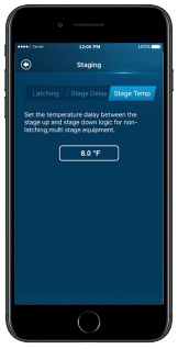
Set the temperature delay between the stage up and stage down logic for non-latching, multi stage equipment.
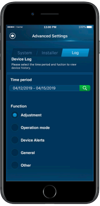
Device Log
- To access the Device Log, click Log on the Advanced Settings screen and enter the Professional Access Code.
- The Device Log stores up to 90 days’ worth of thermostat activity. To view historical data, select the time period you would like to view. Then select the function you would like to view:
Functions
- Adjustment shows changes to temperature set point and hold
- Operation mode shows changes to system mode, fan mode, and power switching
- Device Alerts shows temperature warning information
- General shows changes to temperature units, date, and screen brightness
- Other shows all other information that the thermostat stores
Troubleshooting & Frequently Asked Questions
Wi-Fi
Can the BCC50 be used without Wi-Fi?
We strongly encourage everyone to use the Wi-Fi capabilities of the thermostat, as it will improve the user experience. However, it is fully functional without the use of Wi-Fi after the Initial Setup has been completed with your smartphone.
Will the BCC50 support all Wi-Fi systems & routers?
This device only works with 2.4 GHz systems and is NOT compatible with 5.0 GHz systems or web pages that require additional web authentication.
Trouble Connecting to your Home’s Wi-Fi Network?
- Make sure that your thermostat is a maximum 20 ft or less from the router/modem without any obstructions (i.e. walls, floors, ceilings, etc.). If obstructions exist, try moving your thermostat and router/modem closer together.
- Before attempting to reconnect your thermostat to your home network, power cycle your router/modem and then your thermostat. If you have a separate router and modem, make sure that you power cycle the modem first and then the router.
- In the event that you still cannot connect to your home’s wi-fi network please contact our support team for further in-depth technical troubleshooting options.
NOTE: If you are able to connect to your home network, but the time does not update on the thermostat, you are not fully connected to the cloud server. Please follow the troubleshooting steps again or contact Bosch Technical Support.
Initial Setup
Trouble connecting to your BCC50 Wi-Fi hotspot during Initial Setup?
Go to your phone’s Wi-Fi settings and forget the BCC50 Wi-Fi hotspot. Power cycle the thermostat and attempt the initial setup again.
Trouble advancing to the Unit Configuration portion of the Initial Setup?
Some devices have longer wait times to transfer from the Wi-Fi hotspot connection to the Unit Configuration. If wait times exceed 60 seconds, repeat the Initial Setup process.
Bosch Connected Control App (Android and iOS)
What is the name of the smartphone app in the App Store and Google Play Store?
The name of the app is Bosch Connected Control. Bosch Control is a different Wi-Fi thermostat app used with Bosch Boilers.
How many accounts can be associated with the thermostat at once?
Only one account can be associated with a given thermostat. Family members must share their account information with each other if they would like to be able to control the thermostat from multiple devices.
Can this device be accessed via a web page?
Not at this time.
Thermostat
What happens if I don’t remember the password that locked my screen?
The password will always display on the main screen of your app in the top right hand corner under the green lock button. You can unlock your thermostat by typing this code into the thermostat itself or clicking the green lock button in the top right hand corner of the thermostat. NOTE: this is not the lock button for schedule hold.
What happens if I lose power to the device; will all my setting be lost?
All settings are kept in local memory, except for the schedule setpoints, which are stored in the cloud. Therefore, all settings will e saved even during a power outage.
Not Finding the Answer to Your Question?
Self-support videos can be found on our website at: BoschHeatingAndCooling.com/BCC50
Contact our support team at 1-800-283-3787
Wiring Diagrams
Single Stage Heat – Furnace
Example: Bosch 80% AFUE Gas Furnace – BGS80
▶ Ensure the system has a C-wire
▶ Ensure the pre-installed jumper wire remains between RH and RC
▶ Connect the R, C, W1 and G wires from the Furnace to R/RC, C, W/E/AUX and G terminals on the wall plate, respectively.
Two Stage Heat – Furnace
Example: Bosch 96% AFUE Gas Furnace – BGH96
▶ Ensure the system has a C-wire
▶ Ensure the pre-installed jumper wire remains between RH and R/RC
▶ Connect the R, C, W1, W2 and G wires from the Furnace to R/RC, C, W/E/AUX, O/B/W2 and G terminals on the wall plate, respectively
Single Stage Heat – Boiler
Example: Bosch Greenstar Gas Condensing Boilers*
▶ Ensure the system has a C-wire
▶ Ensure the pre-installed jumper wire remains between RH and RC
▶ Connect the R, C and W1 wires from the boiler to R/RC, C and W/E/AUX terminals on the wall plate, respectively
*NOTE: Bosch Greenstar boilers will require an external transformer to power the thermostat. First remove pre-installed jumper and then connect the dry contacts on the boiler to RH and W/E/AUX on the boiler and the transformer terminals will connect to R/RC and C on the thermostat
Combined Single Stage Heat and Single Stage Cool Furnace and Air Conditioner
▶ Ensure the system has a C-wire
▶ Remove the pre-installed jumper wire from between RH and R/RC
▶ Connect the R, C, W1 and G wires from the Furnace to RH, C, W/E/AUX and G terminals on the wall plate, respectively
▶ Connect the R, C, Y1 and G wires from the Air Conditioner to R/RC, C, Y and G terminals on the wall plate, respectively
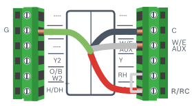
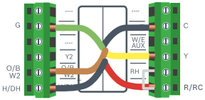
Single Stage Heat Pump
Example: Bosch Inverter Ducted Split
▶ Ensure the system has a C-wire
▶ Ensure the pre-installed jumper wire remains between RH and R/RC
▶ Connect the R, C, Y1, O/B and G wires from the heat pump to R/RC, C, Y, O/B/W2 and G terminals on the wall plate, respectively
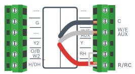
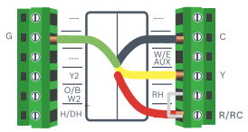
Single Stage Heat Pump with Emergency Heat and Auxiliary Heat
Note: W/E/AUX controls both the Emergency Heat and Auxiliary Heat outputs.
▶ Ensure the system has a C-wire
▶ Ensure the pre-installed jumper wire remains between RH and R/RC
▶ Connect the R, C, W1, Y1, O/B and G wires from the heat pump to R/RC, C, W/E/AUX, Y, O/B/W2 and G terminals on the wall plate, respectively
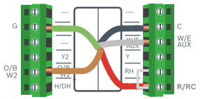
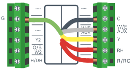
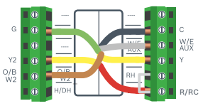
Two Stage Heat Pump with One Stage Emergency Heat
▶ Ensure the system has a C-wire
▶ Ensure the pre-installed jumper wire remains between RH and R/RC
▶ Connect the R, C, W1, Y1, Y2, O/B and G wires from the heat pump to R/RC, C, W/E/AUX, Y, Y2, O/B/W2 and G terminals on the wall plate, respectively
Single Stage Cool – Air Conditioner
▶ Ensure the system has a C-wire
▶ Ensure the pre-installed jumper wire remains between RH and R/RC
▶ Connect the R, C, Y1 and G wires from the Air Conditioner to R/RC, C, Y and G terminals on the wall plate, respectively
Combined Single Stage Heat Pump and Single Stage Furnace (Dual Fuel)
▶ Ensure the system has a C-wire
▶ Ensure the pre-installed jumper wire remains between RH and R/RC
▶ Connect the R, C, W1 and G wires from the Furnace to R/RC, C, W/E/AUX and G terminals on the wall plate, respectively
▶ Connect the C, Y1, G, and O/B wires from the Heat Pump to C, Y, G, and O/B/W2 terminals on the wall plate, respectively
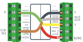
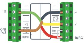
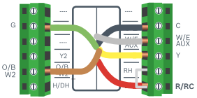
Humidifier or Dehumidifier Accessory with a Single Stage Heat Pump
Note: The wiring configuration for humidifiers and dehumidifiers is the same for all type of Heat Pump Systems
▶ Ensure that the accessory is externally powered
▶ Ensure the Heat Pump System is wired correctly
▶ Connect the control wire of the accessory to the H/DH terminal of the wall plate
User Manual
How to use your BCC50 Thermostat
Use the illuminated buttons to navigate the thermostat. If you do not see the illuminated buttons, simply click on a button’s location to illuminate all the lights.
Note: The screen is not a touch screen. The buttons are the only way to interact with the device. The buttons will turn off after a few seconds of no use.
Thermostat and App Icons
Basic Icons


System Modes


Heating Types


Fan Modes


Accessory


Unit Operation

Heating on (1st stage) & (2nd stage)

Cooling on (1st stage) & (2nd stage)

Heating on (1st stage) & (2nd stage)

Cooling on (1st stage) & (2nd stage)

Fan on/running (Fan Auto Mode)

Heating
Emergency heat on (1st stage) & (2nd stage)

Heating
System Connectivity

Schedule on Device

Schedule on Cloud

Wi-Fi Connection Established

Wi-Fi Connection Not Established

Internet is Not Available

Retry Internet Connection
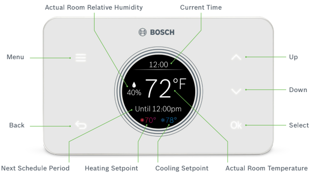
Adjusting Temperature Setpoint(s)
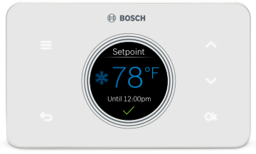
No Schedule
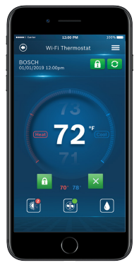
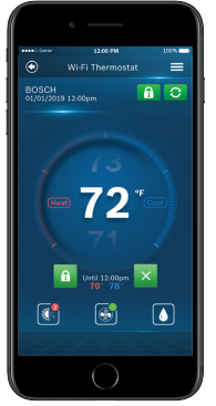
From the Main Screen, use the up or down arrows to change the temperature setpoint, and then press Ok to confirm your selection. You will see a green check mark confirming your selection.
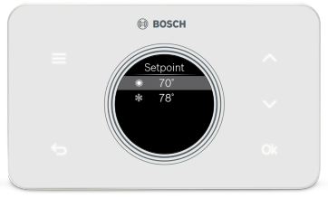
Schedule
Follow the same process as above to change the setpoint, but be aware that you are only changing the setpoint until the next scheduled period listed on the thermostat. If you would like to change the setpoints for the schedule periods, please see the section Schedule further on in this Manual.
Note: The hold feature is not available from the thermostat, only from the app.
Note: When the thermostat is in Auto mode, you must first select either your heating or cooling setpoint depending on which setpoint you would like to modify.
Thermostat Overview
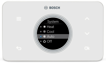
System
Use the up and down arrows to change the system mode of your thermostat between: Heat, Cool, Auto, Emergency Heat (available for Heat Pumps and Dual Fuel systems only) or Off.
Note: From the menu, the red or blue bubble next to the system icon indicates the current system status: on or off, where red signifies heating is on and blue signifies cooling is on.
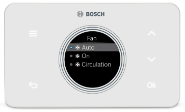
Fan
Use the up and down arrows to change the fan mode of your thermostat between:
- Auto: the fan will automatically turn on when there is a call for heating or cooling (recommended)
- On: the fan will always be on
- Circulation: the fan will turn on and off based on a user programmed schedule.
Note: Circulation schedule can only be programmed from the app.
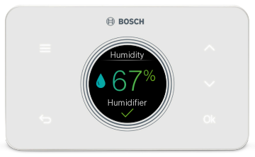
Accessory
Use the up and down arrows to change the relative humidity setpoint, and then press Ok to confirm your selection. You will see a green check mark confirming your selection.
Note: This item will not appear on your thermostat if you did not setup a humidifier or dehumidifier accessory during the initial setup process.
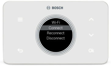
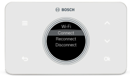
Wi-Fi
Use the up and down arrows to Connect, Re-Connect or Disconnect from your home’s Wi-Fi network.
Note: When you select Connect, refer to page 11 of the Installation Guide to add a new device and connect your thermostat to the Wi-Fi network.
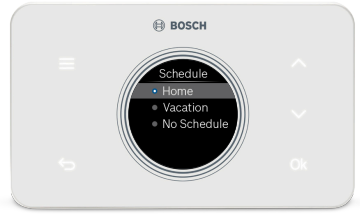
Schedule
Use the up and down arrows to change the active Schedule.
Note: The schedule can only be programmed from the app.
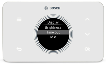
Display
- Select Brightness to adjust the screen’s brightness between high, medium or low.
- Select Timeout to adjust the time before the thermostat enters idle mode: 20 seconds, 1 minute or 3 minutes.
- Select Idle to enable or disable idle mode. Enabling idle mode will always display time and Actual Room Temperature after the timeout period expires.
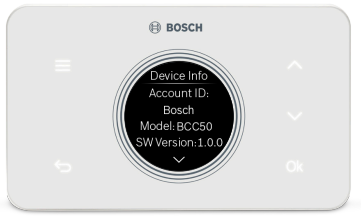
Device Info
Use the up and down arrows to scroll through the following device information:
- Account ID displays the User ID associated with your thermostat.
- Model displays the model number of your thermostat.
- SW Version displays the current software version on your thermostat.
- MAC ID displays the MAC ID associated with your thermostat.
Note: When a system update is available for your thermostat, Click System Update at the bottom of the device information to update your thermostat to a new software version.
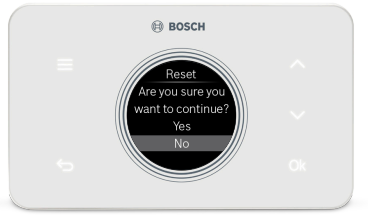
Factory Reset
Click Factory Reset to restore your device to its factory default settings.
Note: All settings will be lost and you will need to repeat the Initial Setup process as outlined in the Installation Guide.
Bosch Connected Control App
The app allows you to remotely control all of your thermostat’s settings. It also allows you to adjust your schedule on-the-go or set it to vacation mode to save energy while you’re away. You can also connect an unlimited number of thermostats and manage up to 4 schedules per thermostat.
This is a perfect solution to help you achieve maximum comfort with minimum effort!
Three Ways to Download The Connected Control App
- In the App Store or Google Play, search “Bosch Connected Control” or “BCC50” and then download the app.
- Visit www.bosch-climate.us/bcc50 or scan QR code below and click the links for the app in the Download App section.
App Screen Overview
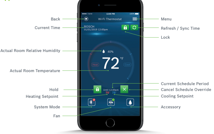
Adjusting Temperature Setpoint(s) on the App
No Schedule
From the Main Screen, tap the current temperature and use your finger to scroll up or down to change the temperature setpoint. Stop on the value you want for
your new setpoint and wait a few seconds for the setpoint to update. You will see the update reflected on the app and on the thermostat.
Note: When the thermostat is in Auto mode, you must first select either heat or cool next to the actual room temperature, depending on which setpoint you would like to modify, and then follow the steps above to change the setpoint.
Schedule
Follow the same process as above to change the setpoint, but be aware that you are only changing the setpoint temporarily, until the next scheduled period
listed on the app. If you would like to change the setpoints for the schedule periods, please see the section Schedule further on in this Manual.
Note: Click the lock icon to override the temperature setpoint permanently. You can cancel the temporary and permanent overrides at any time by clicking the X
icon.
Schedule Overview
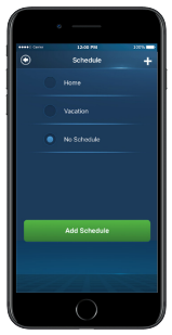
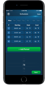
Schedule
- To add a new Schedule, use the ‘+’ button in the top right hand corner, name your schedule and click OK.
- To modify an existing Schedule, select a Schedule from the list and click Next.
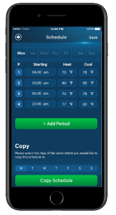
Add a New Period
To add a new Period to a given day, click the Add Period button in the middle of the screen and then individually select and set Starting time, Heat setpoint
and Cool setpoint.
Add a New Period
To add a new Period to a given day, click the Add Period button in the middle of the screen and then individually select and set Starting time, Heat setpoint
and Cool setpoint.
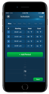
Edit an Existing Period
To edit an existing Period, click on the Starting, Heat or Cool value you would like to edit and use the scroll wheel to update the value.
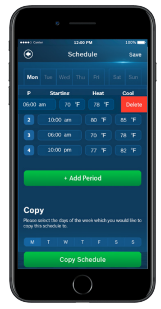
Delete an Existing Period
To delete an existing period, swipe left on the existing period and click delete.
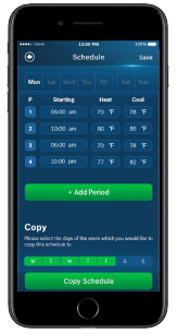
Copy a Schedule
To copy a schedule to other days of the week, click the lettered days at the bottom of the screen until all days you would like to copy the existing schedule have turned green and click Copy Schedule.
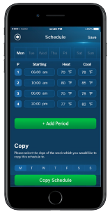
Save Schedule
Use the Save button in the top right hand corner of the screen to save all changes.
App Menu Overview
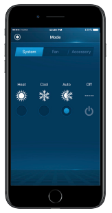
Mode
Similar to the BCC50 Thermostat, use the Mode screens to adjust remotely the System Mode, Fan Mode and Accessory Mode.
Wi-Fi
To change the Wi-Fi Network that your thermostat uses to connect to the internet, follow the on-screen instructions on your app.
Note: Ensure that you have clicked Connect from your Thermostat’s Wi-Fi menu to start the pairing process.
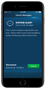
Device Messages
Alert messages regarding your specific thermostat can be read and deleted from this section of the app.
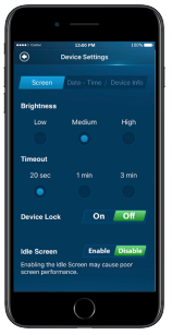
Device Settings
Follow the on-screen instructions to view and modify the thermostat screen settings for brightness, timeout, device lock, date & time and to view specific
account and system information regarding your thermostat.
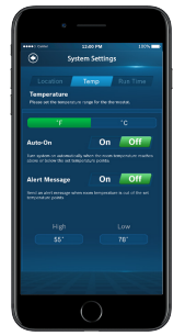
System Settings
Follow the on-screen instructions to change the temperature units, set temperature safety functions, view and reset the run time timers for your thermostat.
Additional Features
Control Your BCC50 with Alexa
Bosch offers one Smart Home Skill for integrating your BCC50 with Alexa’s voice controls. Using the Bosch Connected Control Skill from the Skills section of the
Amazon Alexa App.
You Can Control the BCC50 by Saying:
▶ Alexa, turn (Device Name) on.
▶ Alexa, turn (Device Name) off.
▶ Alexa, Increase (Device Name) by _ _ degrees.
▶ Alexa, Decrease (Device Name) by _ _ degrees.
▶ Alexa, Set (Device Name) to _ _ degrees.
▶ Alexa, what is the (Device Name) set to?
▶ Alexa, what is the temperature of the (Device Name)?
Device Name
The Device Name is the name assigned to your device in the BCC50 app. You can check the device name by opening the BCC50 app and reading the name displayed on the main menu of selectable devices.
The Amazon Alexa commands for the BCC50 are intended for use in Heating Only and Cooling Only modes.
The Amazon Alexa commands for the BCC50 are intended for use in Heating Only and Cooling Only modes.
Connecting Your BCC50 to Alexa
- Download the BCC50 App, create an account, and register your app to the BCC50 thermostat.
- Download the Amazon Alexa app and set up your Alexa-enabled device.
- In the Amazon Alexa app, click on the Menu button in the top left corner.
- Click on the Skills section and search for “Bosch Connected Control” in the search bar at the top of the page.
- After you find and click on the Bosch Connected Control Skill, click on the blue Enable button.
- The setup process redirects you to a Bosch sign-in page where you will need to enter your BCC50 account username and password.
- After you have received confirmation that your two accounts have been successfully linked, click Done in the top left hand corner.
- Next click Discover Devices in the Amazon Alexa app or say “Alexa, discover new devices.” Device Discovery could take up to 45 seconds.
- When device discovery is complete, you should see a list of connected devices in the Smart Home menu of your Amazon Alexa app.
The setup process is now complete and you can start to control your BCC50 with your Alexa-enabled device. Try out some of the commands and enjoy!
For further support, contact our customer service team at: 1-800-283-3787.
Control Your BCC50 with Google Assistant
Once installed and connected to the app, Bosch offers one Smart Home link for integrating your BCC50 with Google Assistant’s voice controls. After setting up your thermostat as a new device in the Google Home app:
You Can Control the BCC50 by Saying:
▶ Hey Google, what’s the _ _ temperature?
▶ Hey Google, make it warmer (or cooler)
▶ Ok Google, set the temperature to _ _ degrees
▶ Ok Google, raise (or lower) the temperature _ _ degrees
▶ “Ok Google, what is the current temperature in the Bedroom?
▶ “Hey Google, what’s the Living Room set to?
▶ “Ok Google, what’s the temperature of my thermostat?
▶ “Ok Google, turn on heat mode in the Bedroom”
▶ “Hey Google, change to automatic mode in the Living Room”
▶ “Ok Google, turn on cool mode in the Kitchen”
Device Name
The Device Name is the name assigned to your device in the BCC50 app. You can check the device name by opening the BCC50 app and reading the name displayed on the main menu of selectable devices.
The Google Assistant commands for the BCC50 are intended for use in Heating Only and Cooling Only modes.
You must have a registered BCC50 account to set up and use your thermostat with Google Assistant.
Connecting Your BCC50 to Google Assistant
- Download the BCC100 app, create an account, and register your app to the BCC100 or BCC50 thermostat.
You must have a registered BCC account to set up and use your thermostat with Google Assistant. - Download the Google Home app and set up your Google-enabled device.
- In the Google Home app, click on the add button in the middle of the screen.
- Click on Setup up device and select the link option under Works with Google. This is the last option on the page.
- Search for Bosch Connected Control and click add new Bosch Connected Control.
- The setup process redirects you to a Bosch sign-in page where you will need to enter your BCC account username and password.
- After you have received confirmation that your accounts have been successfully linked, click Done in the top left hand corner.
- Next choose the device(s) you want to link to your Google Home from the available list and click Next.
- Choose a home for your new thermostat and click Next.
- Choose a location for your thermostat and click Next
The set up process should now be complete and you can start to control your BCC thermostat with your Google-enabled device. Try out some of the commands and enjoy!
Warranty
MODELS COVERED
This limited warranty is provided by Bosch Thermotechnology Corp. (“Bosch”)and covers the Bosch Connected Control BCC50 Thermostat (hereinafter referred to as “Product”). This warranty is provided to the original purchaser of the Product as long as the Product remains installed at its original place of installation.
WARRANTY COVERAGE Limited Warranty
Bosch warrants that the Product will remain free from defects in material and workmanship three (3) years from the date of original installation or from the date of manufacture if proof of installation is not available, provided it is properly installed and the other conditions of this warranty are met. If Bosch determines that the Product has a defect in workmanship or materials, Bosch, at its option, will repair or replace the defective part.
ITEMS NOT COVERED
This limited warranty does not cover the following circumstances:
- Components or parts not provided by Bosch.
- Components or parts, on which the tags or nameplates have been removed, altered or defaced.
- Scratches in or discoloration of finishes.
- The workmanship of any installer. Bosch disclaims and does not assume any liability of any nature for unsatisfactory performance caused by improper installation, repair or maintenance.
- Any labor or material costs for removal, re-installation, repair and replacement of the defective component or part unless otherwise provided above.
- Electricity or fuel costs, or any increases or unrealized savings in same, for any reason whatsoever.
- Damage caused by operation of the Product in a corrosive atmosphere, electrical failures, flooding or acts of God.
- Damage caused by any attachment or modification to the Product, including any energy saving device.
- Damage caused by Product not being installed in accordance with all applicable state and local plumbing and/or building codes and regulations.
- Shipping charges, delivery expenses or administrative fees incurred by the purchaser in repairing or replacing the Product.
LIMITED WARRANTY
OTHER THAN THE OBLIGATIONS OF BOSCH EXPRESSLY SET FORTH HEREIN,BOSCH DISCLAIMS ALL WARRANTIES, EXPRESS OR IMPLIED, INCLUDING BUT NOT LIMITED TO ANY IMPLIED WARRANTIES OF MERCHANTABILITY OR FITNESS FOR A PARTICULAR PURPOSE. BOSCH’S SOLE OBLIGATION WITH RESPECT TO THE PRODUCT AND PURCHASER’S EXCLUSIVE REMEDIES ARE SET FORTH IN THE FOREGOING LIMITED WARRANTY. BOSCH SHALL NOT BE LIABLE FOR ANY INDIRECT, PUNITIVE, INCIDENTAL, SPECIAL, CONSEQUENTIAL OR SIMILAR DAMAGES INCLUDING, WITHOUT LIMITATION, INJURY OR DAMAGE TO PERSONS OR PROPERTY OR DAMAGES FOR LOSS OF USE, LOST PROFITS,INCONVENIENCE OR LOSS OF TIME. NOTE THAT ANY REPAIRED OR REPLACED PRODUCT WILL BE WARRANTED FOR ONLY THE UNEXPIRED TERM OF THE ORIGINAL WARRANTY.
Some states do not allow the exclusion of limitation of damages, or limitations on how long an implied warranty lasts, so the above limitations and exclusions may not apply to you.
WARRANTY CLAIMS PROCESS
Before making a claim under this Limited Warranty, you must contact Bosch Customer Service (+1-800-283-3787), who will support you in troubleshooting the claim and determine if a replacement is covered under this Limited Warranty. To process your claim, you will need a copy of your original invoice or other proof of purchase and documentation showing the original installation date and location. The alleged defective Product must be returned to Bosch in accordance with Bosch procedure then in force for handling goods returned for the purpose of inspection to determine cause of failure (contact Bosch if you have questions regarding the return process). If Bosch determines that the returned product is defective and that this warranty applies, Bosch will furnish the repaired or replacement Product. If you are a contractor, who purchased the product through your distributor, you can also file a claim through your distributor.
This Warranty applies to Bosch Products installed in the Continental United States and Canada only.
You can download the PDF version of the Bosch Connected Control BCC50 Wi-Fi Thermostat User’s Manual here.