INTRODUCTION
Congratulations. You have purchased a precision instrument manufactured to the highest quality standards.This Digital Multimeter is a general-purpose instrument designed for use in general electronics, home electrical applications, and auto-motive electrical/electronic systems.
This meter is designed to test or measure AC voltage, DC voltage, batteries, DC current, AC current, resistance,diodes and continuity.
Please take the time to read these operating instructions thoroughly and completely. Failure to follow these instructions may result in electrical shock, instrument damage and/or damage to the equipment under test. Always use extreme caution when working on or around electrically operated equipment.
SAFETY PRECAUTIONS/ WARNINGS
Do not operate this multimeter before reading this manual in its entirety. The following guidelines must be followed to avoid accidents that can result in electric shock or personal injury.
- Pay close attention to WARNINGS stamped on the front and rear of the meter’s case. These warnings, as well as all warnings and precautions used throughout this manual,must be followed to avoid electric shock and/or personal injury.
- The RESPONSIBLE PARTY shall be made aware that, if the equipment is used in a manner not specified by the manufacturer, the protection provided by the equipment may be impaired.
- Before using any of the functions on this meter, verify its proper operation on a known similar function source where the unit value is also known. Take corrective action based on the indicated results.
To prevent electrical shock and/or damage to the tester or the equipment under test, observe the following safety precautions:
- DO NOT apply more than the rated voltage, as marked on the meter, between terminals or between any terminal and earth ground.
- Use caution when working above 30V AC rms, 42 V peak,or 60 V DC. Such voltages pose a shock hazard.
- To avoid false readings that could lead to possible electric shock or personal injury, replace the batteries as soon as the low battery indicator displays.
- Always inspect the multimeter, test leads and any other accessories for damage prior to every use. If any damage is found, do not use tester until repairs are done.
- Always consider electrical and electronic equipment to be energized (live). Never assume any equipment is de-energized.
- Never ground yourself when taking electrical measurements. Isolate yourself from ground by using dry rubber insulating mats to cover all exposed/grounded metal. Stand on rubber mats and wear dry clothing.
- Never take resistance measurements on energized (live) electrical or electronic equipment.
- Use one hand, instead of two, whenever possible to take measurements. If two hands must be used, use extreme caution not to contact any energized conductors with your hands. Be certain test leads are dry and clean.
- Do not hold the instrument when taking measurements.Place the instrument on a clean, insulating surface prior to taking any measurement.
- Don’t become part of the circuit. Think safety. Act safely.
If working on a vehicle, take the following added precautions:
- Only work on vehicle in a well ventilated area.
- Always wear safety eye protection.
- Avoid moving fan blades or any potentially moving parts.
- Avoid hot engine parts.
- Put transmission in “park” (automatic transmission vehicles) or “neutral” (manual transmission vehicles). Set the parking brake.
- Turn the ignition “off” before connecting or disconnecting any testing equipment.
- Put blocks on drive wheels.
- Avoid wearing loose clothing or jewelry when working on a vehicle.
- Read your vehicle’s service manual and follow it’s safety procedures.
CONTROLS AND INDICATORS
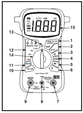
- DCV Function: Measures DC volts. Auto-ranging from 0 to 600 volts (10 MW impedance)
- ACV Function: Measures AC volts. Auto-ranging from 0 to 600 volts (10 MW impedance)
- Resistance Function: Measures resistance. Auto ranging from 0 to 20MW (20,000,000W).
- ACmA Function: Measures AC current in milliamps. One range: 0 to 200 milliamps.
- DIODE Function: For testing diodes.
- CONTINUITY Function: Tests for continuity between two points.
- Volts, mA, OHMS, BAT, DIODE and CONTINUITY Input Jack.
- COM Input Jack: Common Input Jack.
- DC10A Input Jack: For red test lead probe connection when measuring high DC current (up to 10 amps only).
- DC10A Function: Measures DC current. One range: Amps (DC from 0 to 10 amperes). Unfused.
- DCmA Function: Measures DC current in Milliamps. One range: 0 to 200 milliamps.
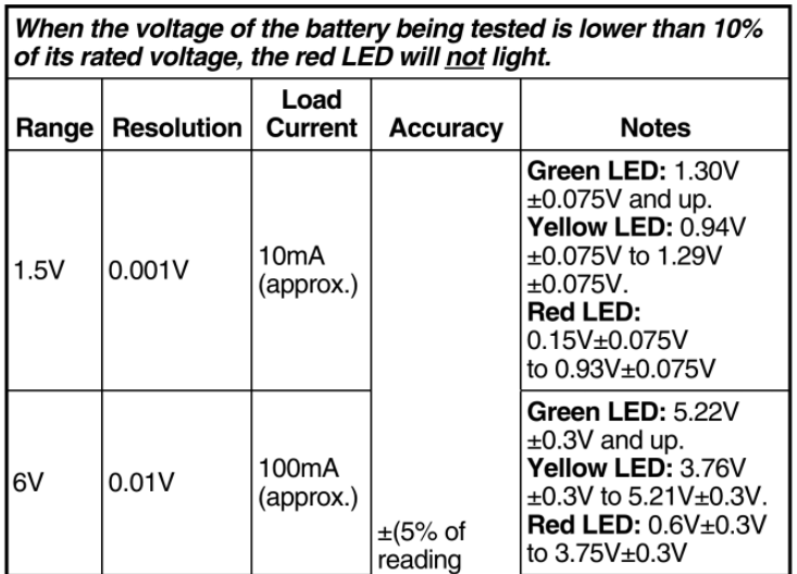
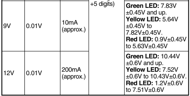
- Battery Test Function: Four ranges and three LEDS (green, yellow and red). Tests small batteries; 1.5V, 6V, 9V and 12V.
- OFF Function: Turns unit “off” when function is selected.
- Function/Range Selector Switch: Selects desired function or range.
- Liquid Crystal Display (LCD): Displays results of tests or measurements.
PREPARATION AND CAUTION BEFORE USE

- Inspect the digital multimeter for damage to the case. Do not use if cracked, distorted, excessively dirty or any abnormal condition exists.
- Inspect the test leads for damage. Check for cracked insulation, broken or damaged probes, loose or bent probe pins. Do not use if any abnormal condition exists.
- Set the Function/Range Selector Switch to the proper range BEFORE taking measurements. If the range/function must be switched during a test, ALWAYS remove the test leads from the circuit being measured before switching settings.
- To avoid possible electric shock, instrument damage, and/or equipment damage when taking voltage or current measurements, DO NOT exceed the maximum value of the selected range.
- If the unit is used near high noise Radio Frequency (RF) generating equipment (spark plug wires, ignition coils or alternator), the display may become unstable or indicate large errors. If you obtain erratic readings during use, isolate the Multimeter as far away as possible from these components.
TESTING PROCEDURES
A. AC/DC VOLTAGE MEASUREMENT

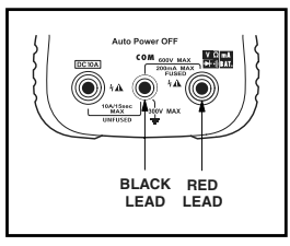
To avoid possible electric shock, instrument damage and/or equipment damage, DO NOT attempt to measure voltages ABOVE 600V AC/DC or take measurements if the voltage is unknown. 600V AC/DC between the COM and V jacks is the maximum voltage that this instrument is designed to measure. The “COM” terminal potential should not exceed 300V AC/DC measured to ground.
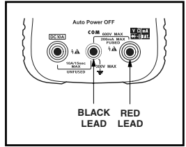
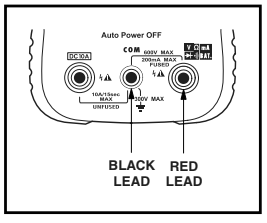
- Plug the BLACK test lead into “COM” jack of the multimeter; plug the RED test lead into the “V” jack.
- Set the meter’s Function/Range Selector Switch to the appropriate ACV or DCV position as desired (see Controls and Indicators, Items 1 and 2).
- Place the RED test lead onto the positive (+) side of the item being tested and the BLACK test lead onto the negative (-) (across the source/load) side of the item. BE CAREFUL not to touch any energized conductors with any part of your body.
- Read the results on the display.
B. RESISTANCE MEASUREMENT W (OHMS)

Resistance measurements must be made on “de energized” (dead) circuits ONLY. Impressing a voltage across the multimeter’s terminals while set to any resistance range may result in electric shock, instrument damage and/or damage to equipment under test. MAKE SURE equipment is completely de-energized before taking any resistance measurements.
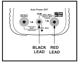
- Plug the RED test lead into the “Ω” jack of the multimeter; plug the BLACK test lead into the “COM” jack.
- Set the meter’s Function/Range Selector Switch to the “Ω” range function (see Controls and Indicators,Item 3).
NOTE:To obtain accurate readings, disconnect at least one side of the item under test from the circuit or circuit board before measuring resistance.
- Place the RED test lead onto one side of the item being tested and the BLACK test lead onto the other side of the item. (Polarity does not matter when checking resistance).
- Read the results on the display.
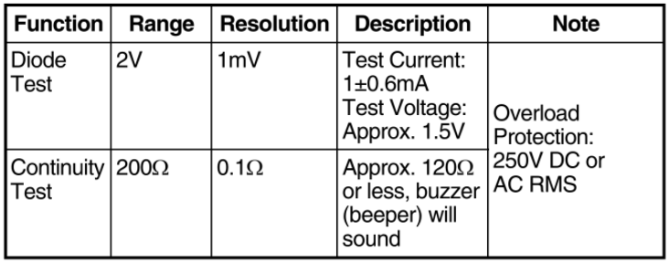
C. DIODE TEST

To avoid electrical shock and/or damage to the multimeter, ensure the power is removed from the circuit before any DIODE testing procedure is conducted. Test diodes on de-energized (dead) circuits only, never on live circuits.
NOTE: A diode is a semiconductor device that lets current flow in one direction only. If the diode to be tested is part of a circuit (with other electronic components), you must isolate it from the other components by disconnecting at least one side of it from the circuit before testing. A good diode will show a low voltage drop across its junction (0.5-0.8 volts for a silicon diode or about 0.3V for a germanium diode) when the leads are connected in one polarity and a very high resistance (or open circuit) when the leads are reversed (connected in the opposite polarity).
- Plug the RED test lead into the jack of the multimeter; plug the BLACK test lead into the “COM” jack.
- Set the meter’s Function/Range Selector Switch to the position (see Controls and Indicators,Item 5)
- Place the RED test lead onto one side of the diode being tested and the BLACK test lead onto the other side.
- Read the results on the display.
- Reverse the test leads and again read the results on the display. Compare the two readings. One reading should indicate a voltage drop value; the other reading should indicate an overrange (OL) condition. See note above.
D. CONTINUITY TEST

To avoid electric shock, shut off the power to the test article before testing it for continuity.
- Plug the RED test lead into the jack of the multimeter;plug the BLACK test lead into the “COM” jack.
- Set the meter’s Function/Range Selector Switch to the position (see Controls and Indicators, Item 6).
- Place the RED Test Lead to one end of the wire or device being tested for continuity and the BLACK Test Lead to the opposite end.
- Listen to the sound of the beeper and confirm the results by reading the display.
NOTE:The beeper will sound only if the continuity of the item under test (resistance between the two test leads) measures less than 120 ohms.
E. AC/DC CURRENT MEASUREMENT (AMPS)

To prevent electrical shock when performing current measurements, follow all steps as indicated below DO NOT skip any steps or take any short cuts.
The DC10A range is not fused. To avoid current hazard and/or damage to the tester, DO NOT try to take measurements on circuits that have more than 10 amps. DO NOT take more than 10 seconds to take the reading. A waiting period of AT LEAST 15 MINUTES is necessary between every 15 second testing period.
- Plug the RED test lead into the “mA” or the “DC10A” jack of the multimeter, as applicable; plug the BLACK test lead to the “COM” jack.
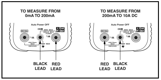
- Set the meter’s Function/Range Selector Switch to the appropriate Amps range position as desired (see Controls and Indicators, Items 4, 10 and 11).
- To measure from 0 to 200mA, set the Selector Switch to the “DCmA” or “ACmA” position, as applicable.
- To measure from 200mA to 10 Amps DC, set the Selector Switch to the “DC10A” position.
- Disconnect the battery, or shut off the power to the circuit being tested.
NOTE:To measure current on a particular circuit, you must open up the circuit and connect the test leads in series with
the circuit before a reading can be obtained.
- Disconnect one end of the wire or device, from the circuit where current will be measured.
- Place the RED test lead on the disconnected wire and place the BLACK test lead at the location from which the wire was disconnected (series connection).
- Reconnect the battery, or apply power to the circuit being tested.
- Read the results on the display.
CAUTION:After the test is completed, shut the power off to the circuit before removing the test leads and before reconnecting any disconnected wires or devices.
NOTE: If the reading obtained is a negative number, reverse the test leads.
F. BATTERY TEST
- Plug the RED test lead into the “BAT.” jack of the multimeter; plug the BLACK test lead into the “COM” jack.
- Determine the voltage rating of the battery to be tested.
- Set the meter’s Function/ Range Selector Switch to the desired “Battery Test” range (see Controls and Indicators,Item 12).
- Place the RED test lead on the positive post of the battery under test; place the BLACK lead on the negative post.
NOTE: If a battery is completely dead, or nearly dead (below 10% of its rated voltage), the red LED will not light.
5.Read the results using the display and the LEDs:
- Green = fully charged (good battery)
- Yellow = low (questionable)
- Red = discharged (bad battery)
NOTE: Battery life is directly proportional to the current draw/load of the device that the battery is powering. The three LEDs on the multimeter represent battery state-of-charge averages for the most commonly used devices.
Battery and Fuse Replacement / Maintenance
BATTERY AND FUSE REPLACEMENT

When replacing the battery or the fuse, remove only the rear panel. Do not remove or disassemble the circuit board or the front panel, these items are not serviceable and if disassembled there is the possibility of loose metal parts shorting the circuit board and causing an electrocution danger to the user.
- Turn the Digital Multimeter “OFF” and remove the test leads.
- Remove the two screws on the back of the meter and separate the case.
- Replace the fuse or batteries as necessary:
- For battery replacement: Remove the batteries from the battery compartment and replace only with two AA (1-1⁄2 volt) alkaline batteries.
- For fuse replacement: Remove the fuse from the fuse holder and replace with a 0.315A/250V – UL Listed Bussmann, GMA Type (Radio Shack GMA/270 series; 270-1046 ) fuse.
NOTE: Use a 0.315A/250V, 5x20mm type fuse ONLY Bussmann, GMA Type (Radio Shack #270-1046 or similar). Using an incorrect fuse may result in serious injury and/or damage to the unit.
4. Reassemble the case and secure with the two screws.
MAINTENANCE
- No periodic maintenance is required other than the replacement of the battery, the fuse, and visual inspection of the meter.
- Keep the meter clean and dry. DO NOT use solvent to clean, use a damp (not wet) cloth and fully dry after cleaning.
- The only replaceable parts are the 1.5 AA batteries, 0.315A/250V fuse (see page 10 for battery and fuse replacement) and the Test Leads (for Test Leads call service department).
SPECIFICATIONS
GENERAL SPECIFICATIONS AND FEATURES
- 3-1⁄2 digit LCD display (maximum reading of 2000); 3 LEDs;green, yellow and red
- Auto Range (ACV, DCV, Ohm, AC mA, and DC mA)
- Automatic negative (-) polarity indication
- Automatic zero adjustment
- Over range indicator (except 10 A function). Displays “OL” on LCD
- Low battery indicator. Displays battery symbol on LCD
- Automatic power shut off (after 15 idle minutes)
- Pollution Degree 2
- Measuring circuit category II
- Operating environment:
- Temperature – 32° to 104° F. (0° C to 40° C)
- Humidity – Less than 80% relative humidity (non-condensing)
- Altitude – up to 6562 ft (2000 meters)
- Storage environment:
- Temperature – 4° to 140° F (- 20° to 60° C)
- Humidity – Less than 90% relative humidity (non-condensing)
- Power Supply: Two 1.5V AA batteries
- Fuse: 315mA/250V 5X20 mm (Radio Shack, GMA/217 series;270-1046) fuse
- Dimensions:
- Height – 5.50 in. (139 mm)
- Width – 3.50 in. (89 mm)
- Depth – 1.25 in. (32 mm)
- Weight (including batteries): approximately 6.3 oz (180 g)
ELECTRICAL SPECIFICATIONS
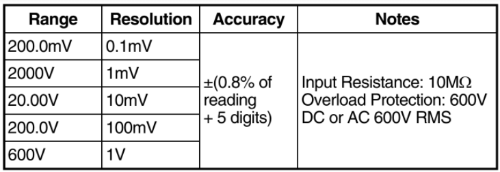
DC VOLTS
| Range | Resolution | Accuracy | Notes |
| 200.0mV | 0.1mV | ±(0.8% of reading + 5 digits) | Input Resistance: 10MΩ Overload Protection: 600V DC or AC 600V RMS |
| 2000V | 1mV | ||
| 20.00V | 10mV | ||
| 200.0V | 100mV | ||
| 600V | 1V |
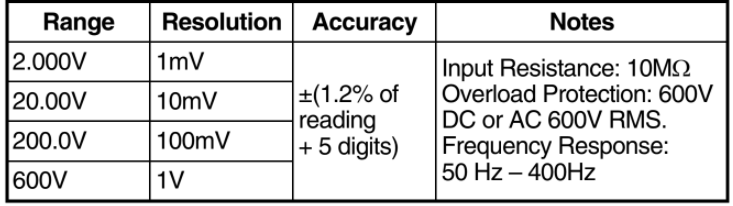
AC VOLTS
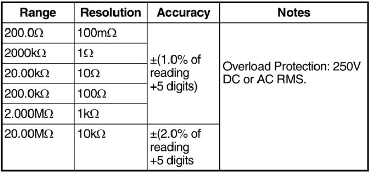
RESISTANCE (OHMS)
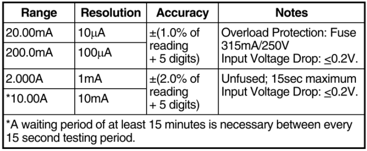
DC AMPS
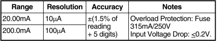
AC AMPS
BATTERY TEST (LEDs)
DIODE/CONTINUITY TESTS
SERVICE PROCEDURES
The Manufacturer warrants to the original purchaser that this unit is free of defects in materials and workmanship under normal use and maintenance for a period of one (1) year from the date of original purchase. If the unit fails within the one (1) year period, it will be repaired or replaced, at the Manufacturer’s option, at no charge, when returned prepaid to the Technical Service Center with Proof of Purchase. The sales receipt may be used for this purpose. Installation labor is not covered under this warranty.
All replacement parts, whether new or re-manufactured, assume as their warranty period for only the remaining time of this warranty.This warranty does not apply to damage caused by improper use, accident, abuse, improper voltage, service, fire, flood, lightning, or other acts of God, or if the product was altered or repaired by anyone other than the Manufacturer’s Technical Service Center.Consequential and incidental damages are not recoverable under this warranty. Some states do not allow the exclusion or limitation of incidental or consequential damages, so the above limitation or exclusion may not apply to you.
This warranty gives you specific legal rights, and you may also have other rights, which vary from state to state. No portion of this warranty may be copied or duplicated without the expressed written permission from the Manufacturer.
Obtaining Warranty Service:
Products requiring service should be returned as follows:
- Call the Technical Service Center to obtain a Return Reference Number:
USA & Canada = 1-800-544-4124 (6am-6pm PST, 7 days a week) Other = 714-241-6805 - Package the product carefully to prevent shipping damage
- Include your name, return address, and a day contact phone
- Enclose a copy of the dated sales receipt
- Describe the problem
- Ship prepaid to: Technical Service Center, 17352 Von Karman
Ave., Irvine, CA 92614 U.S.A.
Phone: 1-800-544-4124 or 714-241-6805
Fax: 714-241-3979
Web: www.equus.com
Email: service@equus.com
You can download the PDF version of the Innova 3320 Auto-Ranging DMM Owner’s manual here.