Professional Install Guide
Package Includes:
• Lyric T6 PRO Wi-Fi Thermostat
• UWPTM Mounting System
• Honeywell Standard Installation Adapter (J-box adapter)
• Honeywell Decorative Cover Plate – Small; size 4-49/64 in = 121mm.
• Screws and anchors
• Professional Install Guide
• Getting Started Guide
Compatibility
• Compatible with most heating, cooling, and heat pump systems
• Required: 24 VAC power (“C”wire)
• Does not work with electric baseboard heat (120-240V)
• Does not work with millivolt systems
• Android oriOS smartphone ortablet
UWP Mounting System installation
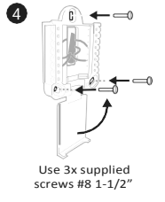
1.Open package to find the UWP.
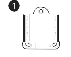
- Position the UWP on the wall. Level and mark hole positions.
Drill holes at marked positions, and then lightly tap supplied wall anchors into wall using a hammer. Drill 7/32” holes for drywall.
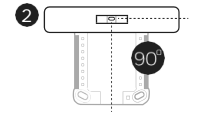
- Pull the door open and insert wires through wiring hole of the UWP.
- Place the UWP over the wall anchors. Insert and tighten mounting screws supplied with the UWP. Do not overtighten. Tighten until the UWP no longer moves. Close the door.
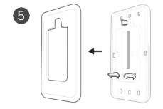
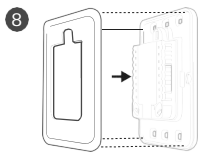
Optional Decorative Cover Plate installation
Use the Optional Cover Plate when:
• Mounting the thermostat to an electrical junction box
• Or when you need to cover paint gap from the old thermostat.
- Separate the Junction Box Adapter from the Cover Plate.
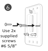
- Mount the Junction Box Adapter to the wall or an electrical box using any of the eight screw holes. Insert and tighten mounting screws supplied with Cover Plate Kit. Do not overtighten. Make sure the Adapter Plate is level.
- Attach the UWP by hanging it on the top hook of the Junction Box Adapter and then snapping the bottom of the UWP in place.
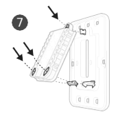
- Snap the Cover Plate onto the Junction Box Adapter.
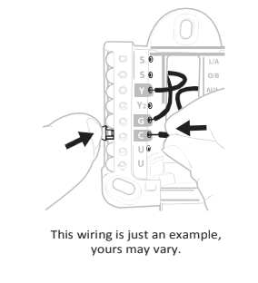
Wiring UWP
Push down on the tabs to put the wires into the inner holes of their corresponding terminals on the UWP (one wire per terminal) until they are firmly in place. Gently tug on the wires to verify they are secure. If you need to release the wires again, push down the terminal tabs
on the sides of the UWP.
Terminal designations
| Conventional Systems | Heat pump systems | ||
| Terminal | Description | Terminal | Description |
| S/S | Input for a wired indoor, outdoor sensor | S/S | Input for a wired indoor, outdoor sensor |
| Y | Compressor Stage 1 | Y | Compressor Stage 1 |
| Y2 | Compressor Stage 2 | Y2 | Compressor Stage 2 |
| G | Fan Relay | G | Fan Relay |
| C | 24VAC Common wire from secondary side of cooling transformer (if 2 transformers) | C | 24VAC Common wire from secondary side of cooling transformer |
| K* | Connect to K on Wire Saver Module | K* | Connect to K on Wire Saver Module |
| U/U** | Relay for ventilation | U/U** | Relay for ventilation |
| A | L/A | Connect to compressor monitor | |
| W | Heat Stage 1 | O/B | Changeover valve for heat pumps |
| W2 | Heat Stage 2 | Aux | Backup Heat |
| E | Emergency Heat | ||
| R | 24 VAC Heating transformer | R | 24 VAC Heating transformer |
| Rc | 24 VAC Cooling transformer | Rc | 24 VAC Cooling transformer |
- The THP9045A1023 Wire Saver Module is used on heat/cool systems when you only have four wires at the thermostat and you need a fifth wire for a common wire. Use the K terminal in place of the Y and G terminals on conventional or heat pump systems to provide control of the fan and the compressor through a single wire—the unused wire then becomes your common wire. See THP9045 instructions
for more information.
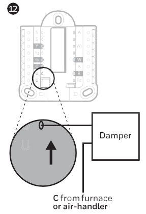
** Ventilation is not available on all models. When the U slider is in the down position (2 wires), the U contacts are a dry set of contacts. If your ventilation system requires 24 volts, move the U slider to the up position (1 wire). Lower U terminal is internally jumped to the Rc terminal. In this application, you would hook up one wire from your damper to the upper U terminal and the other to the common side of
the transformer.
Setting Slider Tabs
Set R Slider Tab, see Figure 9.
• Use built-in jumper (R Slider Tab) to differentiate between one or two transformer systems.
• If there is only one R wire, and it is connected to the R, Rc, or RH terminal on the old thermostat, set the slider to the up position (1 wire).
• If there is one wire connected to the R terminal and one wire connected to the Rc terminal, set the slider to the down position (2 wires).
Set U Slider Tab, see Figure 10.
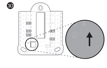
• Use built-in jumper (U Slider Tab) of relay to wire ventilation. Please note that ventilation is not supported on all models.
• When the U Slider Tab is in the down position (2 wires) the U contacts are a dry set of contacts.
• If the ventilator is powered by the cooling transformer, move the jumper switch to the up position (1 wire). With this switch set to 1 wire, the lower U terminal is internally jumped to the Rc terminal. In this application, hook up one wire from the vent damper to the U terminal and the other to the common side of the cooling system transformer.
Wiring
NOTES:
1 Available wiring configurations differ by product models/product numbers.
2 Use 18- to 22- gauge thermostat wire. Shielded cable is not required.
3 Set the R Slider Tab on the UWP to the up position (1 wire) for 1 transformer systems other down position (2 wires) for 2 transformer systems.
4 Set the U Slider Tab to the up position (1 wire) for non-powered ventilation or the down position (2 wires) for powered ventilation.
Conventional systems
1H/1C System (1 transformer)
R Power
Rc [R+Rc joined by Slider Tab]
Y Compressor contactor
C 24VAC common
W Heat relay
G Fan relay
1H/1C System (2 transformers)
R Power (heating transformer)
Rc Power (cooling transformer)
Y Compressor contactor
C 24 VAC common from cooling transformer
W Heat relay
G Fan relay
2H/2C System (1 transformer)
R Power
Rc [R +Rc joined by Slider Tab]
Y Compressor contactor (stage 1)
C 24VAC common
W Heat relay (stage 1)
G Fan relay
W2 Heat relay (stage 2)
Y2 Compressor contactor (stage 2)
Hot Water Relay Panel
R Power
Rc [R+Rc joined by Slider Tab]
W Heat Relay
C 24VAC common
NOTE: If the panel does not provide 24 volts AC at R and C ,set the slider to down position and wire a separate transformer to Rc and C.
Heat-only System with Fan
R Power
Rc [R +Rc joined by Slider Tab]
C 24VAC common
W Heat relay
G Fan relay
Cool-only System with Fan
R Power
Rc [R+Rc joined by Slider Tab]
Y Compressor contactor
C 24VAC common
G Fan relay
Heat pumps systems
1H/1C Heat Pump System
R Power
Rc [R+Rc joined by Slider Tab]
Y Compressor contactor
C 24VAC common
O/B Changeover valve
G Fan relay
2H/1C Heat Pump System
R Power
Rc [R+Rc joined by Slider Tab]
Y Compressor contactor
C 24VAC common
O/B Changeover valve
G Fan relay
Aux Auxiliary heat*
E Emergency heat relay*
L Heat pump fault input
NOTE: If dual fuel, TH6320WF2003 model needed.
2H/2C Heat Pump System
R Power
Rc [R+Rc joined by Slider Tab]
Y Compress or contactor(stage1)
C 24VAC common
O/B Changeover valve
G Fan relay
Y2 Compress or contactor(stage2)
L Heat pump fault input
3H/2C Heat Pump System
R Power
Rc [R+Rc joined by Slider Tab]
Y Compress or contactor(stage1)
C 24VAC common
O/B Changeover valve
G Fan relay
Aux Auxiliary heat*
E Emergency heat relay*
Y2 Compress or contactor(stage2)
L Heat pump fault input
NOTE: TH6320WF2003 only.
NOTE: Do NOT use W for heat pump applications. Auxiliary heat must wire to AUX or E.
If you do not have separate wires for the Aux and E terminals ,connect the wire to the Aux terminal.
Ventilation systems
NOTE: Ventilation is not available on all models.
Using U Slider Tab
Wired to ERV/HRV whole house ventilator with internal power supply.
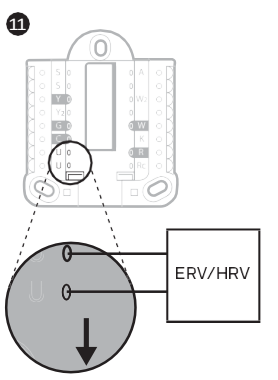
Wired to fresh air damper powered by furnace transformer.
Mounting thermostat
1 Push excess wire back into the wall opening.
2 Close the UWP door. It should remain closed without bulging.
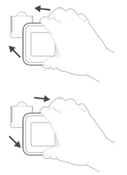
3 Align the UWP with the thermostat, and push gently until the thermostat snaps in place.
4 If needed, gently pull to remove the thermostat from the UWP
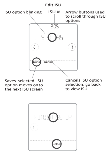
Installer setup – using the thermostat
Setup using the thermostat
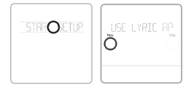
• After the Lyric thermostat has powered up, touch START SETUP on the thermostat. You’ll be asked if you want to perform setup via Lyric app. Touch No.
• Touch or to toggle between Installer Set Up (ISU) options.
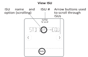
• Touch Edit or touch text area, and then touch or to edit default setup option.
• Touch Done or touch text area to confirm the setting or press Cancel.
• Touch or to continue to setup another ISU option.
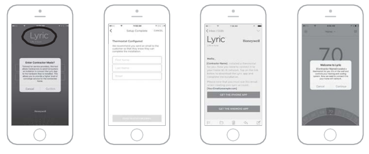
Installer setup – using the Lyric app
Setup using the Lyric app
Download the Lyric app from App Store or Google Play to use a hidden PRO installation feature that will allow you to configure the thermostat and personally invite your customer to connect to the installed thermostat at the same time.

Enter Contractor Mode
To enter Contractor Mode, press and hold the Lyric logo for 5 seconds. Then tap Confirm to begin using Contractor Mode. Follow steps to personally invite your customer to connect their Lyric App.
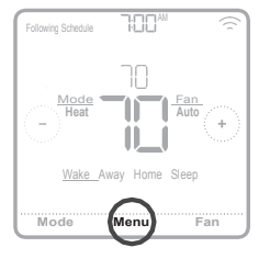
Installer setup – advanced menu
To access the advanced menu, press and hold the Menu button for 5 seconds. Touch or to go through the options in the advanced menu.
Advanced menu options
Device Setup
This is used to access the device ISU setting.
Screen Lock
The thermostat touch screen can be set to lock fully or partially.
Rater View
A read only place to view all the ventilation settings.
System Test
Test the heating and cooling system.
Range Stop (Temperature)
Set the minimum, maximum, cool and heat temperature set points.
Reset
Access all reset options on the thermostat. This is the only place to access factory reset.
Key features
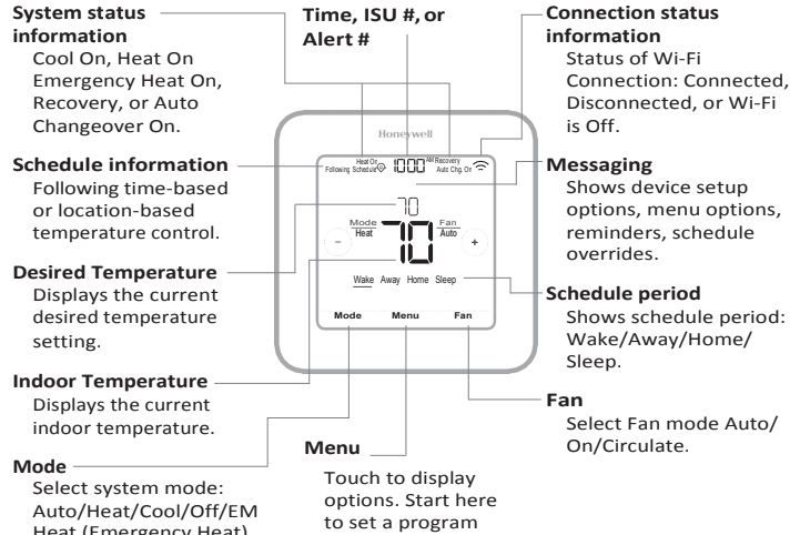
Note: Long press of Menu button for 5 seconds to access Advanced Menu options.
The screen will wake up by pressing the center area of the displayed temperature.
The screen will stay lit for 45 seconds. Brightness can be adjusted in the Menu.
| #ISU | ISU Name | ISU Options (defaults in bold) | Notes |
| 120 | Schedule Type | No Schedule MO-SU = Every day the same MO-FR, SA, SU = 5-1-1 schedule MO-FR, SA-SU = 5-2 schedule Each Day = Every day individual | Youcanchange defaultMO-FR, SA-SUschedule here. Toeditperiods duringdays,temperature setpoints, orto turn Schedule On/Off, from the home screen, go to MENU/SCHEDULE. |
| 125 | Temp Scale | Fahrenheit, Celsius | |
| 130 | Outdoor Temp | No, Wired, Internet | Select outdoortemperature data source. ThisISUautomatically defaultstoInternetwhenregisteredtoLyric appandnowiredoutdoorsensorisselected.Werecommendusingawiredoutdoorsensor connectedtothe“S” terminalsontheUWP.(See”Wiring”onpage5.) AnoutdoortemperatureisrequiredtosetthefollowingISUs:ISU355CompressorLockout,ISU356Aux Heat Lockout, ISU 1013 Low Outdoor Temperature Ventilation Lockout, ISU 1014High Outdoor Temperature Ventilation Lockout, and ISU 1015 High Outdoor Dew Point Ventilation Lockout. |
| 200 | System Type | Conventional Forced Air Heat Pump Boiler Cool Only | Basic selection of system your thermostat will control. |
| 205 | Equipment Type | Conventional Forced Air Heat: Standard Gas (STD GAS), High Efficiency Gas (EFF GAS), Oil, Electric, Fan Coil* Heat Pump: Air To Air, Geothermal Boiler: Hot Water, Steam | This option selectsthe equipmenttype yourthermostat will control. Note: This option is NOT displayed if ISU 200issettoCoolOnly. * Fan coil setting is for a residential application with a hot water coil in an air-handler. |
| 218 | Reversing Valve | 0/B on Cool, 0/B on Heat | ThisISUisonlydisplayedifISU200issettoHeatPump. SelectwhetherreversingvalveO/Bshouldenergize oncool oron heat |
| 220 | Cool Stages (#200=Conv./ 200=HP) | 0, 1, 2 | |
| 221 | Heat Stages/Aux/E Stages (#200=Conv./ 200=HP) | Heat Stages: 0, 1, 2 AUX/E Stages: 0, 1 | Maximum of 2 Heat Stages for conventional systems. Maximum of 1 Aux/E stages for heat pump systems. |
| 230 | Fan Control | Equipment, Thermostat | This ISU is only displayed if ISU 205 is set to Electric Forced Air or Fan Coil. |
| 253 | Aux/E Control | Both Aux/E, Either Aux/E | Set “EITHER AUX/E” if you wantto setup and control Auxiliary and Emergency heating separately . ThisISUis onlydisplayedifISU200issettoHeatPumpANDifISU221Aux/E stages=1. |
| 255 | Aux Heat Type | Electric, Gas/Oil (or Fossil Forced Air) | ThisISUis displayedonlyifISU200issettoheatpumpANDifISU221Aux/Eheatstages=1. Note:OptionsofthisISUmayvarydependingonthemodel ofthe thermostat. |
| # ISU | ISU Name | ISU Options (defaults in bold) | Notes |
| 256 | EM Heat Type | Electric, Gas/Oil (or Fossil Forced Air) | ThisISUis displayed only ifISU200 issettoHeatPump ANDifISU221Aux/E heatstages= 1 ANDifISU253 issettorunAUX/E heatseparately. Note: This ISU may not be available at all on some models. |
| 260 | Fossil Kit Control | Thermostat, External(FossilFuelKitControlsBackup Heat) | ThisISUis displayedonly ifISU200issettoHeatPumpANDifISU221Aux/E heatstages= 1,ANDifISU256 issetto Gas/Oil. Note: This ISU may not be available at all on some models. |
| 300 | Auto Changeover | On, Off | OFF:Theusermustselectheatingorcoolingasneededtomaintainthedesired indoor temperature. ON (Automatic):On(enabled) Allows usertoselectAutoChangeover as one ofthesystemmodesfrom the home screen. In automode,the thermostat cancontrol either heating or cooling to maintain the desired indoor temperature. |
| 303 | Auto Differential | 0 °F to 5 °F or 0.0 °C to 2.5 °C | Differential istheminimumnumber of degreesrise orfallrequired during off cycle toswitch fromthe last activemode(heator cool)totheoppositemodewhenthe thermostatisinauto-changeover.Differential is NOT deadband. The deadbandtemperature between whenheating (or cooling) cyclesonandcyclesoffto maintain setpointis not adjustable.Honeywell uses an algorithmthatfixes deadbandat 0°F. |
| 305 | High Cool Stage Finish | Yes, No | ThisISUis only displayed when the thermostatissetto 2 coolstages. When setto YES, thisfeature keepsthe higherstage ofthe coolingequipmentrunninguntilthe desiredsetpointisreached. |
| 306 | High Heat Stage Finish | Yes, No | ThisISUis only displayed when the thermostatissetto 2 ormore heatstages. When setto YES,thisfeature keepsthe higherstage ofthe heatingequipmentrunninguntilthe desiredsetpointisreached. |
| 340 | Aux Heat Droop | 0 = Comfort; 2 °F to 15 °F from setpoint (in 1 °F incre ments)or1.0°Cto7.5°Cfromsetpoint(in0.5°Cincrements) | Auxheatdroopcanbesetonheatpumpsystemswithanauxiliaryheatstage.TheComfortsettingisNOT availableforDualFuelsystems.Defaultsettingis0°F(Comfort)forElectricwhile2°FforGas/Oil.Theindoor temperaturemustdroptotheselecteddroopsettingbeforethethermostatwillturnAuxHeaton.Forexample, ifAuxHeatissetto2°F(1.0°C),theindoortemperaturemustbe2°F(1.0°C)awayfromthesetpointbefore AuxHeatturnson.WhensettoComfort,the thermostat will useAuxHeat asneededtokeep the indoortem perature within 1 °F (0.5 ° C) degree of the setpoint. |
| 350 | Up Stage Timer Aux Heat | Off, 30, 45, 60, 75, 90 minutes 2, 3, 4, 5, 6, 8, 10, 12, 14, 16 hours | The AuxiliaryHeat Upstage Timerstarts when the higheststage ofthe previous heating equipmenttype turns on. Auxiliary heat will be used (if needed) when the timer expires. ThisISUis only displayed when ISU340 (AUX HeatDroop)issetto2°Forhigher. |
| 355 | Balance Point (Compressor Lockout) | Off, 5°F to60°F (in5°F increments)or-15.0 °Cto15.5°C (in2.5 °C or3.0 °C increments) | Compressor Lockout requires an outdoor temperature. Set Compressor Lockout to the temperature below whichitisinefficienttorunthe heatpump.When outside temperature isbelow thissetting,thermostatwill lockoutheatpumpandrunAuxHeatonly.ThisISUisonlydisplayedifISU130=WiredorInternet,ISU200is settoHeatPump,ISU221Aux/Estages=1,ANDISU260issettoThermostat.Werecommendusingawired remote sensor as an outdoor temperature source. Defaultis40°FifISU205HeatingEquipmentisAirtoAirHeatPumpandISU255AuxHeatTypeisGas/Oil. DefaultisOffifISU205HeatingEquipmentisAirtoAirHeatPumpandISU255AuxHeatTypeisElectric. Default is Off if ISU 205 Heating Equipment is Geothermal. Compressor Lockout is optional for any type of heat pump (Air to Air Heat Pump, Geothermal Heat Pump). |
| # ISU | ISU Name | ISU Options (defaults in bold) | Notes |
| 356 | AuxHeatLockOut (AuxHeatOutdoor Lockout) | Off, 5 °F to 65 °F (in 5 °F increments) or -15.0 °C to 18.5 °C (in 2.5 °C or 3.0 °C increments) | AuxHeat Lockoutrequires anoutdoortemperature. SetAuxHeat Lockouttooptimize energybills andtonot allowittorunthemore expensiveAuxHeatsource above certainoutdoortemperature limit. ThisISUisonly displayedifISU200issettoHeatPump,ANDISU260issettoThermostatcontrolANDifISU221Aux/E stages=1. |
| 365 | Cool 1 CPH (Cooling cycle rate stage 1) | 1 – 6 CPH (3 CPH) | This ISU is only displayed when Cool/Compressor Stagesissetto1ormorestages.Cycleratelimitsthemaxi mum number of timesthe system can cycle in a 1 hour period measured at a 50% load. For example, when set to3CPH,ata50%load,themostthesystemwillcycleis3timesperhour(10minuteson,10minutesoff). The system cycles less often when load conditions are less than or greaterthan a 50% load. |
| 366 | Cool 2 CPH (Cooling cycle rate stage 2) | 1 – 6 CPH (3 CPH) | This ISU is only displayed when Cool /Compressor Stages is set to 2. |
| 370 | Heat 1 CPH (Heating cycle rate stage 1) | 1 – 12 CPH | ThisISUisonlydisplayedwhenHeatStagesissetto1stageormorestages.Cycleratelimitsthemaximum numberoftimesthesystemcancycleina1hourperiodmeasuredata50%load.Forexample,whensetto3 CPH,ata50%load,themostthesystemwillcycleis3timesperhour(10minuteson,10minutesoff). The systemcyclesless often when load conditions are lessthan or greaterthan a 50% load. The recommended (default) cycleratesettingsarebelowforeachheatingequipmenttype: Standard Efficiency Gas Forced Air = 5 CPH; High Efficiency Gas Forced Air = 3 CPH; Oil Forced Air = 5 CPH; Electric Forced Air = 9 CPH; Fan Coil = 3 CPH; Hot Water RadiantHeat = 3 CPH; Steam = 1 CPH. |
| 371 | Heat 2 CPH (Heating cycle rate stage 2) | 1 – 12 CPH | ThisISU is only displayed when Heat Stagesisset to 2 stages. The recommended (default) cycle rate settings arebelowforeachheatingequipmenttype: Standard Efficiency Gas Forced Air = 5 CPH; High Efficiency Gas Forced Air = 3 CPH; Oil Forced Air = 5 CPH; Electric Forced Air = 9 CPH; Fan Coil = 3 CPH; Hot Water RadiantHeat = 3 CPH; Steam = 1 CPH. |
| 375 | Aux Heat CPH (Heating cycle rate Auxiliary Heat) | 1 – 12 CPH | ThisISUisonlydisplayedwhenISU200=HeatPumpandISU221=1.ItisonlydisplayedwhenAuxiliaryHeat is configured.Therecommendedcycle ratesettingsarebelowforeachheatingequipmenttype: Standard Efficiency Gas Forced Air = 5 CPH; High Efficiency Gas Forced Air = 3 CPH; Oil Forced Air = 5 CPH; Electric Forced Air = 9 CPH. |
| 378 | EM Heat CPH (Heating cycle rate Emergency Heat) | 1 – 12 CPH | ThisISUisonlydisplayedwhenEmergencyHeatisconfiguredandISU253:Aux/ETerminalControlissetto controlAux andE heatIndependently. The recommendedcycle rate settings are belowfor eachheatingequip ment type: Standard Efficiency Gas Forced Air = 5 CPH; High Efficiency Gas Forced Air = 3 CPH; Oil Forced Air = 5 CPH; Electric Forced Air = 9 CPH. |
| 387 | Compressor Protection | Off, 1 – 5 minutes | The thermostat has a builtincompressor protection(minimumofftimer)that preventsthe compressorfrom restartingtooearlyafterashutdown.Theminimum-offtimerisactivatedafterthecompressorturnsoff.If there is a call during theminimum-offtimer,the thermostatshows “Wait” inthe display. ThisISUis displayedif ISU220issettoatleast 1stage. |
| 390 | Ext Fan Run Time in Cool | Off, 30, 60, 90 seconds 2, 3, 4, 5, 6, 7, 8, 9, 10, 11, 12, 13, 14, 15 minutes | Afterthe callfor cooling ends,the thermostat keepsthe fan on forthe selectedamount oftime forincreased efficiency.Thismayreintroducehumidityintothelivingspace.ThisISUis displayedifISU220issettoatleast 1stage. |
| # ISU | ISU Name | ISU Options (defaults in bold) | Notes |
| 391 | Ext Fan Run Time in Heat | Off, 30, 60, 90 seconds 2, 3, 4, 5, 6, 7, 8, 9, 10, 11, 12, 13, 14, 15 minutes | Afterthe callforheatingends,the thermostat keepsthe fan onforthe selectedamountoftime forincreased efficiency.ThisISUisdisplayedifISU230issettoThermostatControlsFan. |
| 425 | Adaptive Recovery | On, Off | Adaptive IntelligentRecovery (AIR)is a comfortsetting.Heatingor coolingequipmentwillturnonearlier, ensuringtheindoortemperaturewillmatchthesetpointatthescheduledtime. |
| 429 | Max Cool Temperature | fromMin.CoolTemp.to99°Forto37.0°C(90°For32°C) | The user cannot set the cooling temperature above this level. |
| 430 | Min Cool Temperature | from50°For 10.0 °CtoMax.CoolTemp.(50 °F or 10 °C) | The user cannot set the cooling temperature below this level. |
| 431 | Max Heat Temperature | fromMin.HeatTemp.to90°Forto32.0°C(90°For32°C) | The user cannot set the heating temperature above this level. |
| 432 | Min Heat Temperature | from40°For4.4°CtoMax.HeatTemp.(50 °F or 10 °C) | The user cannot set the heating temperature below this level. |
| 500 | Indoor Sensor | Yes, No | SetthisISUwhenyouwanttowirearemoteindoorsensortothe“S” terminalsontheUWP -see”Wiring”on page5.ThisISUisonlydisplayedonlyifISU130issettoNOwiredoutdoorsensorconfigured |
| 515 | Sensor type | 10k, 20k | Choose resistance type of wired indoorsensor. ThisISUis only displayed when indoorsensoris configured ISU500. |
| 520 | Temperature Control | Thermostat, Wired, Average | ThisISUisonlydisplayedwhenindoorsensorisconfigured-ISU500.Youcanchoosewhattemperature source tobe usedor youcanask thermostattouse both thermostat and remote sensorsfor higher accuracy of measurement. |
| 702 | Air Filters | 0 – 2 | This ISU refers to the number of air filters in the system. |
| 711 | Air Filter 1 Reminder | Off 10, 20, 30, 45, 60, 90, 120, 150 Run Time Days 30, 45, 60, 75 Days 3, 4, 5, 6, 9, 12, 15 Months | Choose either calendar or equipment run time-based reminder. |
| 712 | Air Filter 2 Reminder | Off 10, 20, 30, 45, 60, 90, 120, 150 Run Time Days 30, 45, 60, 75 Days 3, 4, 5, 6, 9, 12, 15 Months | Choose either calendar or equipment run time-based reminder. |
| 810 | Hum Pad Reminder | Off 6, 12 Calendar Months | |
| 921 | Dehum Filter Reminder | Off 30, 60 Calendar Days 3 – 12 Calendar Months (in 1 month increments) |
| # ISU | ISU Name | ISU Options (defaults in bold) | Notes |
| 1000 | Vent Type | None, ERV/HRV, Passive, Fresh Air Damper | None: The thermostat does not control ventilation. ERV/HRV:ThethermostatcontrolsanEnergyRecoveryVentilatororHeatRecoveryVentilatorforventila tion. Passive (FanOnly): Thethermostatturnsonthefanfor ventilation.Whensettopassivefan,thethermo stat does not control a damper or ventilator. The passive ventilation/passive fan setting only runsthe indoor blowerfan. Thissetting doesnotopena damper orruna ventilator. Touse thissetting for ventilation,the home wouldneedtobeset-upwitha pipefromoutdoorsintothereturnductthatiseitherpermanentlyopenorhasa damperthatautomaticallyopenswhenevertheblowerfanison. Note: Some models only offer the passive fan setting. |
| 1005 | Vent Method | ASHRAE 2010, ASHRAE 2013, Percent On Time | Note: Options of this ISU may vary depending on the model of the thermostat. |
| 1006 | Vent Fan Control | Thermostat, Equipment | Thermostat: The thermostat turns on the ventilation and the fan when ventilation is needed. Equipment: Ventilation equipment controls the blower fan. |
| 1007 | Bedrooms | 1 – 6 (2) | This ISU is only displayed when ISU 1005 Ventilation Method is set to ASHRAE 2010 or 2013. |
| 1008 | Home Size | 1000 – 5000 Sq. Ft. (1000 Sq. Ft.) | This ISU is only displayed when ISU 1005 Ventilation Method is set to ASHRAE 2010 or 2013. |
| 1009 | Vent Rate | 30 – 350CFM (in 5CFM increments) (150CFM) | This ISU is only displayed when ISU 1005 Ventilation Method is set to ASHRAE 2010 or 2013. |
| 1011 | Vent Percent On Time | 10% – 100% (30%) | The thermostat operates ventilation equipment based on a percentage entered in the installer setup (ISU 1012). For example, if Percent on Time issetto 50%, the ventilation equipment willrun atrandomtimes dur inga1hourperioduntilitreachesa50%runtime(approximately30minutes).ThisISUisonlydisplayedif ISU1005issettoPercentOnTime. |
| 1012 | Vent Priority | Lockouts, ASHRAE | Lockouts are Priority:ThethermostatplacesapriorityonlockoutsversustheASHRAEventilation standard. The thermostatwill notrunventilationduring the following lockout conditions(if configured), unless youmanuallycallforventilation: Lockout Ventilation during Outdoor Conditions (ISU 1013, 1014 and 1015). LockoutVentilationduring“Sleep” programperiods.Note:ThisoptionissetbytheuserontheVentilation screenintheMenu. ASHRAE is Priority: ASHRAE requires additional ventilation following a long off cycle. The thermostat meetsthe ASHRAE ventilationstandard by running additional ventilationwhen outdoor conditions are favor able.IfASHRAE cannotbemetwhenoutdoor conditionsarefavorable,thethermostatwilloverridetheoutdoor lockoutsandrunventilation.Whenusingthisoption,itisrecommendedthatyouincreasetherate(CFM)of the ventilationequipmenttomeettheASHRAE ventilationstandardina shorterruntime. The ability tolockout ventilationduring the“Sleep” isnotanoptionwhenyouselectASHRAE isPriority. |
| 1013 | Low Outdoor Temp Vent Lockout | Off, -20 °F to -40 °F (in 5 °F increments) or -28.0 °C to -4.0 °C (in 2.0 °C increments) | ISU130mustbesettoWiredorInternet.ThisISUisonlydisplayedwhenISU1000VentilationTypeissetto ERV/HRVor FreshAirDamper. |
| 1014 | High Outdoor Temp Vent Lockout | Off, 80°F to110°F (in5°F increments)or 26°Cto44°C(in2°Cincrements) | ISU130mustbesettoWiredorInternet.ThisISUisonlydisplayedwhenISU1000VentilationTypeissetto ERV/HRV or Fresh AirDamper. |
| 1015 | High Outdoor Dewpoint Vent Lockout | Off, 65°Fto85°F(in5°Fincrements)or 18°Cto30°C(in2°Cincrements) | ISU130mustbesettoInternet.ThisISUisonlydisplayedifISU1000VentilationTypeissettoERV/HRVor Fresh Air Damper. |
| #ISU | ISU Name | ISU Options (defaults in bold) | Notes |
| 1017 | Vent Core Reminder | Off, 3, 6, 9, 12 months | This ISU is displayed only if ISU 1000 is set to ERV/HRV. |
| 1018 | Vent Filter Reminder | Off, 3, 6, 9, 12 months | |
| 1100 | UV Devices | 0 – 2 | SomesystemsmayhavetwoUVdevices,onefortheA-CoilandanotherforAirTreatment.Areplacement remindercanbesetupforeachoneseparately. |
| 1105 | UV Bulb 1 Reminder | Off, 6, 12, 24 months | |
| 1106 | UV Bulb 2 Reminder | Off, 6, 12, 24 months | |
| 1401 | Idle Brightness | 0= Off, 0 – 5 | Adjust brightness of an inactive backlight(idle screen) fromdefault 0 (backlight off) to 5 (maximum brightness). |
| 1410 | Clock Format | 12 hour, 24 hour | |
| 1415 | Daylight Saving | On, Off | Set to Off in areas that do not follow Daylight Saving Time. |
| 1420 | Temp Offset | Off, -3 °F to 3 °F (in 1 °F increments) or -1.5 °C to 1.5 °C (in 0.5 °C increments) | 0°F -No difference in displayed temperature and the actualroomtemperature. The thermostat candisplayup to 3 °F (1.5 C) lower or higherthan the actualmeasured temperature. |
Performing a system test
You can test the system setup in ADVANCED MENU under SYSTEM TEST option.
1 Press and hold Menu on the Lyric thermostat for 5 seconds to access ADVANCED MENU options.
2 Touch or to go to SYSTEM TEST.
3 Touch Select or touch text area.
4 Touch or to select system test type. Touch Select or touch text area.
5 For the heat test and cool test, use or to activate each stage of the equipment. For the fan test, use or to turn the fan on and off.
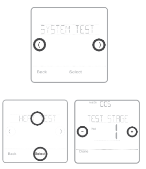
NOTE: The clock is used as a timer while the stages are running. The Heat On and Cool On indicators are displayed when the system test
is running.
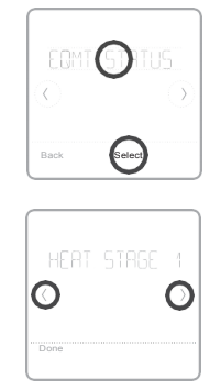
Viewing equipment status
You can see the status of thermostat controlled equipment in the Menu under the EQMT STATUS option.
1 Touch Menu on your thermostat.
2 Touch or to go to EQMT STATUS. Touch Select or touch text area.
3 Touch or to view statuses of all the equipment the thermostat is controlling. Depending on what feature the thermostat supports or how it was installed, the Equipment Status screen reports data for the following systems:
• Heating and cooling
• Fan
• Ventilation (available on certain models only)
Troubleshooting
Screen is blank
• Check circuit breaker and reset if necessary.
• Make sure power switch at heating and cooling system is on.
• Make sure furnace door is closed securely.
Screen is difficult to read
• Change screen brightness in thermostat Menu. Increase brightness intensity for inactive back light of the thermostat screen(max.islevel5).
Heating or cooling system does not respond
• Touch Mode to set system to Heat. Make sure the temperature is set higher than the Inside temperature.
• Touch Mode to set system to Cool. Make sure the temperature is set lower than the Inside temperature.
• Check circuit breaker and reset if necessary.
• Make sure power switch at heating &cooling system is on.
• Make sure furnace door is closed securely.
Heat runs with cooling
• Verify there is not a wire attached to W for heat pump systems.
Alerts and reminders
Alerts and reminders are displayed via the alert symbol and alert number in the clock area on the home screen. You can read more information about active alerts, snooze or dismiss non-critical alerts in Menu/Alerts.
| Number | Alert/Reminder | Definition |
| 164 | Heat Pump Needs Service | Heat pump needs service. Contact dealer to diagnose and service heat pump. |
| 168 | Wi-Fi Radio Error | Wireless module is not operating. Wireless features are not available. Please contact dealer to replace the thermostat. |
| 170 | Internal Memory Error | The memory of the thermostat has encountered an error. Please contact dealer for assistance. |
| 171 | Set the Date and Time | Set the date and time on your thermostat. The date and time are required for certain features to operate, like the program schedule. |
| 173 | Thermostat Temperature Sensor Error | The sensor of the thermostat has encountered an error. Please contact dealer to replace the Thermostat. |
| 175 | AC Power Resumed | AC power resumed to thermostat after power loss. |
| 177 | Indoor Temperature Sensor Error | Wired indoor temperature sensor is not connected or there is a wiring short. Please contact dealer for assistance. |
| 178 | Outdoor Temperature Sensor Error | Wired outdoor temperature sensor is not connected or there is a wiring short. Please contact dealer for assistance. |
| 181 | Replace Air Filter (1) | Replace air filter (1). Reset the timer by touching the “dismiss” button on thermostat screen after it is replaced |
Alerts and remnders
| Number | Alert/Reminder | Definition |
| 182 | Replace Air Filter (2) | Replace air filter (2). Reset the timer by touching the “dismiss” button on thermostat screen after it is replaced. |
| 183 | Clean Humidifier Tank and Replace Water Filter | Clean humidifier tank and replace the water filter, or contact dealer to do this for you. Reset the timer by touching the “dismiss” button on the thermostat screen after it is replaced. |
| 184 | Replace Humidifier Pad | Replace humidifier pad. Reset the timer by touching the “dismiss” button on the thermostat screen after it is replaced. |
| 185 | Replace Dehumidifier Filter | Replace the dehumidifier filter. Reset the timer by touching “dismiss” button on thermostat screen after it is replaced. |
| 186 | Clean Ventilator Core | Clean ventilator core. Reset the timer by touching the “dismiss” button on thermostat screen after it is replaced. |
| 187 | Clean or Replace Ventilator Filter | Clean or replace ventilator filter. Reset the timer by touching the “dismiss” button on thermostat screen after it is replaced. |
| 188 | Replace UV Bulb (1) | Replace UV Bulb (1). Reset the timer by touching the “dismiss” button on thermostat screen after it is replaced. |
| 189 | Replace UV Bulb (2) | Replace UV Bulb (2). Reset the timer by touching the “dismiss” button on thermostat screen after it is replaced. |
| 210 | Register Online For Outdoor Temperature | Online registration is required to receive outdoor temperature from the Internet. Outdoor temperature is needed for your current system setup. Download the Lyric app to register your thermostat. |
| 388 | Register Online for Remote Access and Outdoor Temperature | Online registration is required for remote access and out door temperature .Download the Lyric app to registery our thermostat. |
| 399 | No Internet | The connection to the Internet has been lost. Please check your network settings. |
| 400 | No Wi-Fi Signal | The Wi-Fi signal has been lost. Please wait for the thermostat to reconnect or select a new Wi-Fi network. Follow steps in the Lyric app |
| 508 | Wi-Fi Not Configured | Please download the Lyric app and follow the steps to connect thermostat to your Wi-Fi network. |
CAUTION: ELECTRICAL HAZARD
Can cause electrical shock or equipment damage. Disconnect power before beginning installation.
CAUTION: EQUIPMENT DAMAGE HAZARD
Compressor protection is bypassed during testing. To prevent equipment damage, avoid cycling the compressor quickly.
CAUTION: MERCURY NOTICE
If this product is replacing a control that contains mercury in a sealed tube, do not place the old control in the trash. Contact your local waste management authority for instructions regarding recycling and proper disposal.
Specifications
Temperature Ranges
Heat: 40 °F to 90 °F (4.5 °C to 32.0 °C)
Cool: 50 °F to 99 °F (10.0 °C to 37.0°C)
Operating Ambient Temperature
37 °F to 102 °F (2.8 °C to 38.9 °C)
Shipping Temperature
-20 °F to 120 °F (-28.9 °C to 48.9 °C)
Operating Relative Humidity
5% to 90% (non-condensing)
Physical Dimensions in inches (mm) (H x W x D)
Lyric T6 PROWi-Fi Thermostat(TH6320WF2003):
4-5/64 x 4-5/64 x 1-1/16 (104 x 104 x 27)
Lyric T6 PRO Wi-Fi Thermostat (TH6220WF2006):
4-5/64 x 4-5/64 x 1-1/16 (104 x 104 x 27)
UWP Mounting System (included):
2-9/32 x 2-13/64 x 2-43/64 (58 x 56 x 10)
Standard Installation Adapter (THP2400A1076):
3-29/32 x 3-57/64 x 21/32 (99 x 99 x 17)
Decorative Cover Plate – Small (included):
4-49/64 x 4-49/64 x 11/32 (121 x 121 x 9)
Decorative Cover Plate – Large (THP2400A1068):
6-7/64 x 6-7/64 x 9/32 (155 x 155 x 7)
Electrical Ratings
| Terminal | Voltage (50/60Hz) | Running Current |
| W Heating | 20-30 Vac | 0.02-1.0 A |
| (Powerpile) | 750 mV DC | 100 mA DC |
| W2 (Aux) Heating | 20-30 Vac | 0.02-1.0 A |
| E Emergency Heat | 20-30 Vac | 0.02-0.5 A |
| Y Compressor Stage 1 | 20-30 Vac | 0.02-1.0 A |
| Y2 Compressor Stage 2 | 20-30 Vac | 0.02-1.0 A |
| G Fan | 20-30 Vac | 0.02-0.5 A |
| O/B Changeover | 20-30 Vac | 0.02-0.5 A |
| L/A Input | 20-30 Vac | 0.02-0.5 A |
| U | 20-30 Vac | 0.02-0.5 A |
5-year limited warranty
For Warranty information go to http://customer.honeywell.com
Power Consumption
Backlight On: 1.48VA
Backlight Off: 0.88VA
Regulatory information
FCC REGULATIONS § 15.19 (a)(3)
This device complies with part 15 of the FCC Rules.
Operation is subject to the following two conditions:
1 This device may not cause harmful interference, and
2 This device must accept any interference received, including interference that may cause undesired operation.
IC REGULATIONS RSS-GEN
This device complies with Industry Canada’s license-exempt RSSs.
Operation is subject to the following two conditions:
1 This device may not cause interference; and
2 This device must accept any interference, including interference that may cause undesired operation of the device.
FCC Warning (Part 15.21) (USA only)
Changes or modifications not expressly approved by the party responsible for compliance could void the user’s authority to operate the equipment.
You can download the PDF version of the Honeywell LyricTM T6ProWi-fi programmable Thermostat user manual here.