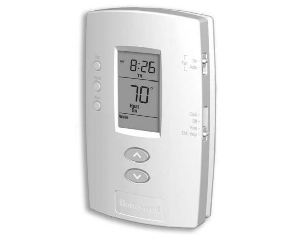
This manual covers the following models:
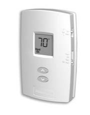
non-programmable thermostats
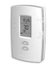
programmable thermostats
(Remove the thermostat from its wallplate to find the model number.)
System Types
TH1110D and TH2110D:
- Central heating – gas, oil, electric or high-efficiency furnace (1H)
- Central heating (see above) with air conditioning (1H/1C)
- Hot water system (steam or gravity) with or without pump
- Central air conditioners
- 750 mV heating systems
- Heat pumps with auxiliary heating (2H/1C)
TH1210D and TH2210D:
- Heat pumps with auxiliary heating (2H/1C)
TH1110D
- Central heating – gas, oil, electric or high-efficiency furnace (1H)
- Hot water system (steam or gravity) with or without pump
- 750 mV heating systems
Must be installed by a trained, experienced technician
Read these instructions carefully. Failure to follow these instructions can damage the product or cause a hazardous condition.
Need Help?
For assistance with this product please visit http:/fyourhome.honeywell.com
or call Honeywell Customer Care toll-free at 1-800-468-1502.
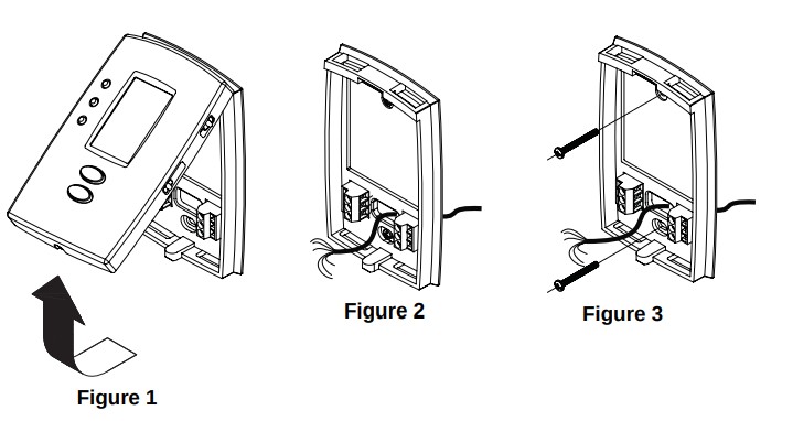
Wallplate Installation
CAUTION: Electrical Hazard: Can cause electrical shock or equipment damage. Disconnect power before beginning installation.
- Loosen the locking screw at the bottom of the thermostat. Note that the screw is captive and cannot be removed from the wallplate.
- Separate the thermostat from the wallplate as per Figure 1 below.
- Position the wallplate against the wall and mark hole positions with a pencil. NOTE: Levelling is for esthetics only and will not affect the performance of the thermostat.
- Drill holes at the marked positions and insert supplied wall anchors.
- Pass the wires through the large opening located at the bottom center of the wallplate as per Figure 2.
- Secure the wallplate to the wall with supplied mounting screws as per Figure 3.
- Connect the wires to the terminals.
Mercury Notice: If this product is replacing a control that contains mercury in a sealed tube, do not place the old control in the trash. Contact your local waste management authority for instructions regarding recycling and proper disposal.
Wiring
- Power supply. Provide disconnect means and overload protection as required.
- Set the O/B jumper according to the type of reversing valve.
- Use a piece of wire (not supplied) to connect W and Y terminals to each other.
- Optional 24 VAC common connection. If this connection is not made, use batteries to power the thermostat.
- This connection is not required for systems that provide heating only.
- This connection is not required for systems that provide cooling only.
- This connection is not required for systems that do not have an air recirculating fan.
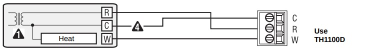
Gas, oil or electric heating (1H)
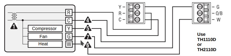
Gas, oil or electric heating and/or air conditioning (1H / 1C / 1H1C)
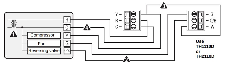
Heat pump without auxiliary heating (1H1C)
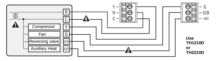
Heat pump with auxiliary heating (2H1C)
Reversing Valve Setting
NOTE: This setting is necessary only if the thermostat is connected to a heat pump.
The jumper is located on the back of the thermostat faceplate. Set it according to the type of reversing (changeover) valve used by the heat pump.
- (factory setting): The reversing valve is energized when the System switch is set to Cool (cooling mode).
- B: The reversing valve is energized when the System switch is set to Heat (heating mode).
Incorrect jumper setting: The heat pump operation will be reversed; i.e., it will cool in Heat mode and will heat in Cool mode.
Fan operation setting
NOTE: This setting is not applicable if a fan is not connected to the G terminal.
A jumper, located on the back of the thermostat faceplate, determines how the fan operates in Automatic mode. This jumper is not available on TH1100, TH1210D and TH2210D. On these models, when the fan is placed in Automatic mode, it starts right away when there is a call for heat or cool.
- HG (factory setting): Leave the jumper in this position for gas or oil heating systems. In this position, the heating system controls the fan operation. When there is a call for heat, the fan starts only when the air coming out of the vents is sufficiently warm. When there is a call for cool, the fan starts right away.
- HE: Place the jumper to this position for heat pump or electric heating systems. In this position, the thermostat activates the fan as soon as there is a call for heat or cool.
Incorrect jumper setting: An incorrect setting is noticeable in a gas or oil heating system. When heating starts, you will initially feel cold air coming out of the vents as the fan is running before the furnace has enough time to heat up the air.
Battery Installation
If a 24-VAC common wire is connected to the C terminal, batteries are optional and serve to provide backup power.
If a 24-VAC common wire is not connected to the C terminal, batteries are necessary to power the thermostat.
Install 2 AAA batteries on the back of the thermostat faceplate as shown.
Thermostat mounting
- Align the two brackets on the top of the thermostat with the corresponding slots on the top of the wallplate.
- Push the faceplate against the wallplate.
- Tighten the screw at the bottom of the thermostat.
Installer setup
Follow the procedure below to personalize and configure the thermostat according to the heating/ cooling system.
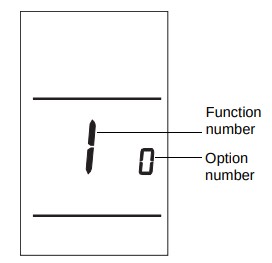
- Press [ Up ] and[ Down ]simultaneously (for three seconds) until the display appears as shown
- Press [ Up ] or [ Up ] to change the option.
- Press [ Up ]and [ Down ] for one second to advance to the next function.
- When the last function is displayed, press [ Up ] and [ Down ] for three seconds to save any changes and exit the menu.
NOTE: If you do not press any button for 60 seconds while you are in the setup menu, the thermostat automatically saves any changes made and exits the menu. For programmable models only, at any time you can save the changes and exit by pressing the Run button.
| Function | Default setting | Options |
| Temperature display format | O | 0:Fahrenheit1:Celsius |
| Time display format | 0 | 0:12-hour display1:24-hour display |
| Heating cycles per hour | 5 | 2 to 6 cycles per hour2:30 min (steam, gravity)3:20 min (hot water,90%+high-efficiency furnace4:15 min (gas or oil)5:12 min (gas or oil)6:10 min (electric) |
| Cooking cycles per hour | 3 | 2 to 6 cycles per hour |
| Compressor protection | 1 | 0:off1:on |
| Adaptive Intelligent Recovery | 1 | 0:off1:on |
| application | 0 | 0:Indoor mode:40F to 90F (4.5C to 32C)1:Garage mode:35F TO 90F (1.5C to 32C) |
- Depending on your thermostat model or your system type, some functions are non-available or non-applicable.
- Damage can occur if the compressor is restarted too soon after shutdown. This feature forces the compressor to wait 5 minutes before restarting. During the wait time, the message Cool On or Heat On flashes on the screen. When the safe wait time has elapsed, the message stops flashing and the compressor turns on.
- Adaptive Intelligent Recovery™ allows the thermostat to “learn” how long your furnace or air conditioner takes to reach the set temperature. Simply program the desired times and desired temperatures into the schedule. The thermostat will determine when to activate heating or cooling so that the desired temperature is attained at the desired time.
- In Indoor mode, the minimum setpoint is 40°F (5°C) for frost protection. In Garage mode, the minimum setpoint is 35°F (1.5°C) for energy savings.
Specifications
Temperature Ranges
- Heat: 40 °F to 90 °F (4.5 °C to 32 °C)
- Cool: 50 °F to 99 °F (10 °C to 37 °C)
Operating Ambient Temperature
- 32 °F to 122 °F (0 °C to 50 °C)
- Shipping Temperature
- -40 °F to 130 °F (-40 °C to 55 °C)
Operating Relative Humidity
- 5% to 90% (non-condensing)
Physical Dimensions
- 47°H x 2.9″ W x 1.1” D (120 mm H x 74 mm W x 28 mm D)
Power Supply
- 24 VAC or 2 AAA batteries
Maximum Load
- 1A @ 24 VAC per output
You can download the PDF version of the Honeywell Pro 1000 or 2000 installation guide here.