SPECIFICATIONS
Operating Specifications
• Station Count: Conventional wiring from 4 to 23 stations, Two-wire EZ Decoder option up to 32 stations
• Station Run Time: 1 minute to 6 hours on programs A, B, and C
• Start Times: 4 per program, three programs for up to 12 starts
• Watering Schedule: 7-day calendar, interval watering up to a 31-day interval or true odd or even day programming, made possible by the 365-day clock/calendar
Electrical Specifications
• Transformer Input: 120 VAC, 60 Hz (230 VAC, 50/60 Hz for international use)
• Transformer Output: 24 VAC, 1 amp
• Station Output: 24 VAC, 0.56 amps per station
• Maximum Output: 24 VAC, 0.84 amps (includes Master Valve Circuit)
• Battery: 9-volt alkaline battery (not included) used only for non-AC programming; the non-volatile memory maintains program information
• Battery, front panel, internal CR2032 lithium for real-time clock
Cabinet Dimensions
Height: 9″ (23 cm)
Width: 10″ (21.5 cm)
Depth: 4 1/ 2″ (10.9 cm)
Outdoor cabinet is NEMA 3R, IP44 rated.
Default Settings
All stations are set to zero run time. This controller has a non-volatile memory that retains all entered program data even during power outages, without the need for a battery.
Cleaning
Clean only with cloth dampened with mild soapy water.
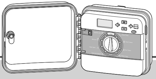
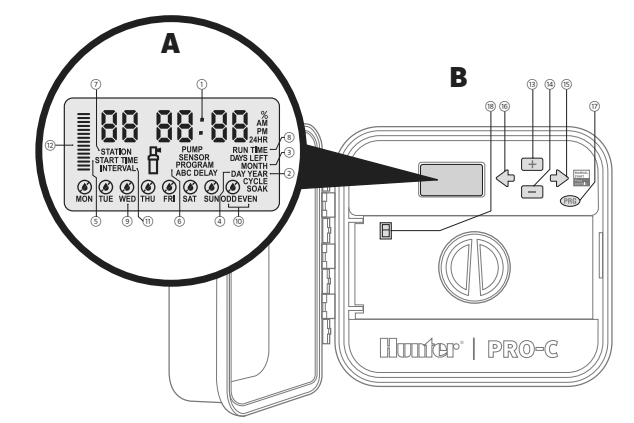
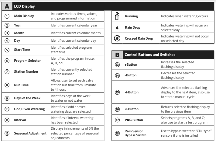
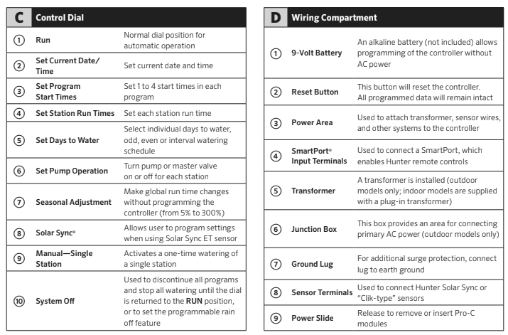
PRO-C COMPONENTS
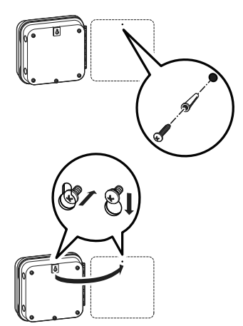
MOUNTING THE CONTROLLER TO A WALL
All necessary hardware is included for most installations.
- Use the hole at the top of the controller as a reference and secure a 1″ (25 mm) screw into the wall. Note: Install screw anchors if attaching to drywall or masonry wall.
- Align controller with the screw and slide the keyhole on top of the controller over the screw.
- Secure controller in place by installing screws in the holes.
For PC-401-A: If the supply cord is damaged, it must be replaced by the manufacturer or service agent or a similarly qualified person to avoid hazard.
NOTE: The indoor Pro-C is not weather- or water-resistant, and must be installed indoors or in a protected area. This device is not intended for use by young children. Never let children play with this device.
The outdoor model is water- and weather- resistant. Connecting the outdoor Pro-C to the primary power should be done by a licensed electrician following all local codes. Improper installation could result in shock or fire hazard. This device is not intended for use by young children. Never let children play with this device.
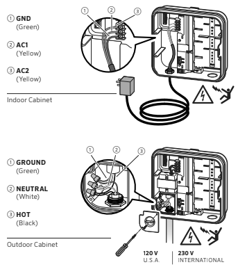
CONNECTING AC POWER
Indoor Cabinet
Route transformer cable through the hole on the bottom left side of the controller and connect one Yellow Wire to each of the screws marked AC and the Green wire to GND.
WARNING: To be performed by a licensed electrician only.
Always use UL listed 1⁄2” (13 mm) conduit with male adapter when installing AC wiring. Pro-C/PCC controllers are intended to be supplied AC power with a
15A rated overcurrent protected device.
Outdoor Cabinet
- Route AC power cable and conduit through the 1⁄2″ (13 mm) conduit opening on the left side of the bottom of the cabinet.
- Connect the wires to the transformer wires located inside the junction box. International units are supplied with a built-in terminal strip. Always use a UL listed conduit 1⁄2″ (13 mm) male adapter when installing the AC wiring.
- Insert the adapter into the 1⁄2″ (13 mm) hole at the bottom of the controller. Attach a nut to the adapter inside the enclosure.
- Connect a 9-volt alkaline battery (not included) to the battery terminals and place in the battery compartment in the front panel. The battery allows the user to program the controller without AC power. Watering will not occur without AC power.
Since this controller has non-volatile memory, the program clock and calendar will be retained during a power outage even if no battery is installed.
INSTALLING STATION MODULES
The Pro-C controller is supplied with a factory-installed base module for up to 4 stations. Additional modules may be added in increments of 3 stations (PCM-300), 9 stations (PCM-900), or 16 stations (PCM-1600). In total, a conventionally wired system can be expanded up to 23 stations. Additional modules are sold
separately.
The Pro-C is also compatible with the EZ Decoder System (EZDS) for hybrid conventional and two-wire operations. Add a Pro-C Decoder Module (PC-DM) to enable control for up to 32 total stations. This system uses the same EZ-1 decoders used with ICC2 and HCC controllers. For more installation and programming details, please refer to the PC-DM Installation Guide.
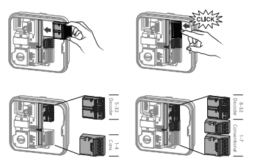
Installing PCM Modules
The Pro-C controller is designed with a simple-to-use “Power Lock” feature that assures that the modules are energized and firmly secured into the controller. The “Power Lock” can unlock or lock all modules at once or at the same time by simply pushing the “Power Lock” slide.
- Slide the “Power Lock” into the “Power Off” (unlocked) position. Insert the PCM or PC-DM modules into the appropriate sequential position in the controller cabinet.
- Once all of the modules are in place, slide the “Power Lock” into the “Power On” (locked) position to energize and secure the modules into the controller.
- The Pro-C will automatically recognize the correct number of stations. It is not necessary to press the reset button on the back of the facepack or cycle power to the controller.
WARNING: NOTE: To expand your controller to 16 or 23 stations with a PCM-900 or PCM-1600, respectively, install one PCM-300 in the first expansion slot (stations 5–7). Then install the PCM-900 or PCM-1600 in the upper two expansion slots. These modules will not fit or operate in any other station output slot.
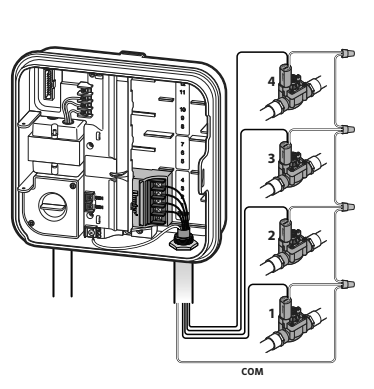
CONNECTING STATION WIRES
- Route valve wires between control valve location and controller.
- At valves, attach a common wire to either solenoid wire of all valves. This is most commonly a white colored wire.
Attach a separate control wire to the remaining wire of each valve. All wire splice connections should be done using waterproof connectors. - Route valve wires through the conduit and attach conduit to one of the openings on the bottom of the cabinet.
- Strip 1⁄2″ (13 mm) of insulation from ends of all wires.
Secure the valve common wire to “COM” (Common) terminal.
Attach all individual valve control wires to the appropriate station terminals.
WARNING: NOTE: The common terminal screw has moved from the base module and is now below the sensor terminals. Do not connect the incoming common wires to the P/MV terminal.
CONNECTING THE BATTERY (OPTIONAL)
NOTE: Warning: Risk of fire, explosion, and electric shock. Replace battery with CR 2032 type only. Use of a different battery has potential risk for fire, explosion, and electric shock. See owner’s manual for instructions.
Connect a 9-volt alkaline battery (not included) to the battery terminals and place in the battery compartment in the front panel. The battery allows the user to program the controller without AC power. Watering will not occur without AC power.
Since this controller has non-volatile memory, the program clock and calendar will be retained during a power outage even if no battery is installed.
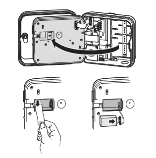
Activating the 3V Lithium Battery
After installing your Pro-C, make sure to remove the battery contact insulator to allow the Pro-C to keep time in the event of a power outage.
WARNING: NOTE: When installing 3V lithium battery, ensure the positive (+) side is facing up.
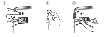
Replacing the 3V Lithium Battery
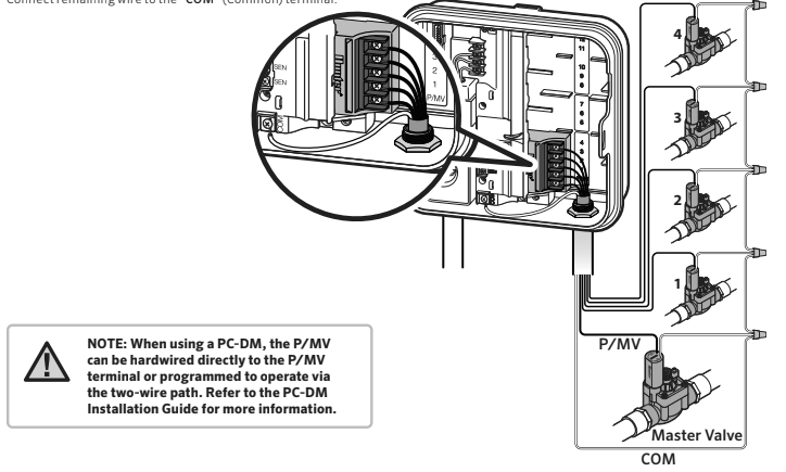
Connecting a Master Valve (optional)
Connect either wire from Master Valve to the P/MV terminal.
Connect remaining wire to the “COM” (Common) terminal.
CONNECTING A PUMP START RELAY (OPTIONAL)
- Route a wire pair from the pump relay into the controller housing.
- Connect the pump common wire to the terminal slot “COM” (Common) and the remaining wire from the pump relay to the P/MV terminal slot.
Relay holding current draw must not exceed 0.28 amps (24 VAC). Do not connect the controller directly to the pump—damage to controller will result.
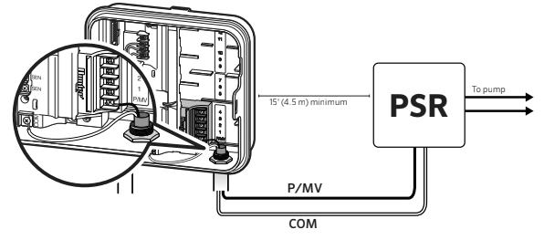
For more information on the installation of a PSR, please visit the support page: https://hunter.direct/pumpstartrelay
CONNECTING A HUNTER “CLIK” WEATHER SENSOR (NOT INCLUDED)
A Hunter weather sensor or other micro-switch-type weather sensors can be connected to the Pro-C. The purpose of this sensor is to stop automatic watering when weather conditions dictate.
- Remove the metal jumper plate that is attached across the two SEN terminals inside the controller.
- Connect one wire to one SEN terminal, and the other wire to the other SEN terminal.
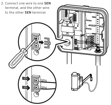
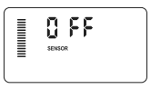
When the weather sensor has deactivated automatic watering, “OFF” will appear on the display.
Testing the Weather Sensor
The Pro-C provides simplified testing of a rain sensor when the sensor is wired into the sensor circuit. You can manually test proper operation of the rain sensor by using the One – Touch Manual Start (see page 30). During the Manual cycle, pressing the test button on the “Clik-type” sensor (e.g., Mini-Clik®) will interrupt watering.
Manually Bypassing the Weather Sensor
If the rain sensor is interrupting irrigation, you can bypass it by using the bypass switch on the front of the controller.
Slide the switch to the Bypass position to disable the rain sensor from the system to allow for controller operation. You can also bypass the weather sensor for manual operation by using the Manual function. The Bypass switch does not affect the Seasonal Adjust update when using the Solar Sync sensor.
WARNING NOTE: The Manual single-station function ignores any attached sensor and will allow watering to occur.

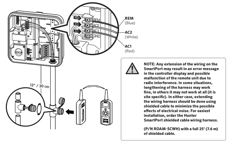
CONNECTING A HUNTER REMOTE (NOT INCLUDED)
The Pro-C is compatible with Hunter remote controls.
The SmartPort wiring harness (included with all Hunter remotes) allows for fast and easy use of Hunter controls.
Hunter remotes make it possible for you to operate the system without having to walk back and forth to the controller.
To Install the SmartPort Connector
- Install a 1/ 2″ PVC Slip x Slip x FIPT in the field wiring conduit approximately 12″ (30 cm) below the Pro-C.
- Feed the red, white, and blue wires of the harness through the base of the “Tee” and into the wiring compartment as shown.
- Screw the SmartPort harness housing into the “Tee” as shown.
- Attach the red wire to the screw slot marked AC1, attach the white wire to the screw slot marked AC2, attach the blue wire to the screw slot marked REM.
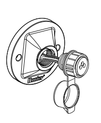
NOTE: P/N 258200 can be used as an alternate method to mount the SmartPort connector.
NOTE: Reversing the red and white wires will result in an “SP ERR” message.
CONNECTING TO THE HUNTER SOLAR SYNC®
The Solar Sync is a sensor system that, when connected to Hunter Pro-C, will automatically adjust your controller watering based upon changes in local climate conditions. The Solar Sync utilizes a solar and temperature sensor to measure on-site weather conditions used to determine evapotranspiration (ET), or the rate at which plants and turf use water. In addition, the Solar Sync sensor includes a Hunter Rain-Clik® and Freeze-Clik® sensor that will shut down your irrigation system when it rains and/or during freezing conditions.
The controller will automatically increase or decrease watering run times based on changes in weather. The result is a new water-efficient irrigation product that promotes water conservation and healthier plants. You simply program your controller like you normally would, and the Solar Sync takes over from there, eliminating the need to manually adjust your watering schedule.
For installation and programming instructions of your Hunter Solar Sync, please refer to the Solar Sync owner’s manual or visit the Solar Sync support section on our website: https://hunter.direct/solarsynchelp
CONNECTING A HUNTER SOLAR SYNC®ET SENSOR
This controller is compatible with the Solar Sync and Wireless Solar Sync systems. Solar Sync is a sensor system that will automatically adjust the controller’s watering schedule (based on changes in local climate condition) by using the Seasonal Adjust function. The Solar Sync uses a solar and temperature sensor to determine evapotranspiration (ET), or the rate at which plants and turf use water, and also includes Hunter Rain-Clik and Freeze-Clik technology that will shut down irrigation when it rains and/or during freezing conditions.
NOTE: Solar Sync will apply a default seasonal adjust value of 100% until the first full day (24-hour period) of weather measurements have been received from the sensor.
NOTE: Enabling the Sensor Bypass switch has no effect on the seasonal adjust updates from the Solar Sync sensor. It will, however, bypass the Rain-
Clik and Freeze-Clik functionality of the sensor.
Installing Solar Sync Sensor
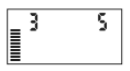
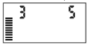
Connect the Green and Black wire from the Solar Sync Sensor to the “SEN” wiring terminals on the controller. It does not matter which wire connects to which terminal. Turn the dial to the “Solar Sync Settings” position. The display will initially show dashed lines and then will show the default Region setting (3) on the left and the default Water Adjustment setting (5) on the right.
Adjust the Region as needed by using the UP and DOWN buttons (refer to page 21 for explanation of Solar Sync Region setting).
Use the SIDE button to advance to the right to adjust the Water
Adjust setting as needed (see page 22 for explanation of Water Adjust setting).
Installing the Wireless Solar Sync
Connect the Green and Black wire from the Wireless Solar Sync Receiver to the “SEN” wiring terminals on the controller. It does not matter which wire connects to which terminal.
Turn the dial to the “Solar Sync Settings” position. The display will initially show dashed lines and then will show the default Region setting (3) on the left and the default Water Adjustment setting (5) on the right. Adjust the region as needed by using the UP and DOWN buttons (refer to page 13 for explanation of Solar Sync Region setting). Use the button SIDE to advance to the right to adjust the Water Adjust setting as needed (see page 14 for explanation of Water Adjust setting).
Solar Sync Settings
Once the Solar Sync sensor is connected to the controller, two numbers will appear in the display when the dial is turned to the Solar Sync Settings position. The number on the left of the screen is the Region setting, and the number on the right on the screen is the Water Adjustment setting (as shown above).
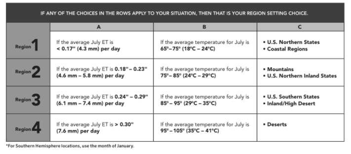
Region
For accurate Solar Sync measurements, the controller needs to be programmed for the average peak season ET for your region. Use the table below to determine your region. The table will assist you in identifying the type of region you live in. There are four basic ET regions, each with descriptions of the
region, along with typical ET and temperature characteristics. It is recommended that, if possible, the region be chosen based upon average July ET or peak summer ET (inches/mm per day).
Use the following table for choosing your region (reference below). You can use methods A, B, or C to help you choose which region is
best for your area:
A: Based upon the ET of your region using the average July ET or peak summer ET (inches/mm per day). This is the preferred option when selecting your region.
B: Based upon the temperature for your region using the average July or the driest month high temperature (not the highest temperature for July).
C: Based upon the general description of your region.
Water Adjustment
The Water Adjustment is a 1 to 10 scale that allows for easy adjustment of the Seasonal Adjust value from the Solar Sync ET Sensor. Upon installation of the Solar Sync ET Sensor, keep the Water Adjustment setting at the default value of 5. However, after installation, if you find that the seasonal adjust value is lower or
higher than expected, the Water Adjustment value can be modified to the Seasonal Adjust output value. See Calibration/Setup on page 15 for explanation of how to use Water Adjustment scale to fine-tune seasonal adjust output value.
NOTE: If an individual zone is “wetter” or “drier” than the rest of the system, simply increase or decrease the amount of run time on the controller.
Uninstalling a Solar Sync Sensor
If a Solar Sync sensor has been installed, then the seasonal adjust value used by the controller will be calculated from the weather data supplied by the Solar Sync sensor.If the Solar Sync sensor is no longer used with the controller, it must be uninstalled. If the Solar Sync sensor is not uninstalled, the controller will not allow the seasonal adjust value to be manually changed. For example, if the seasonal adjust value shown on the controller was 50 percent when the Solar Sync sensor was removed, it will remain 50 percent until the Solar Sync sensor is uninstalled.
To uninstall the Solar Sync sensor, simply disconnect the green and black wires from the controller terminal and then turn the dial to the “Solar Sync Settings” position. The display should show dashes,indicating that the controller no longer recognizes the Solar Sync sensor for calculation of seasonal adjustment. Now the seasonal adjust value can be changed manually by turning the knob to the Seasonal Adjust” position and using the + or – button to adjust the value.
Calibration/Setup
After Solar Sync has been installed and programmed, allow the system to run for a few days at the initial setting. Because of the variety in site conditions (including sensor location, amount of direct sunlight available to the sensor, reflective heat from surrounding structures, etc), the initial setting may require adjustment to arrive at the desired performance. The calibration of the Solar Sync to a particular site can easily be accomplished by adjusting the Region and/or Water Adjustment settings. The instructions below outline this process:
- Install Solar Sync sensor
- Program Region and allow system to operate at initial setting for a minimum of 3 days
- Observe the Seasonal Adjust on the controller. If the Seasonal Adjust amount appears to be lower or higher than expected for that time of year, the Solar Sync settings need to be adjusted.
a. Seasonal Adjust too low: Turn the dial to the Solar Sync settings position. Increase the value on the Water Adjustment scale (10 is max). Once the setting is changed, the controller will immediately be updated with the new Seasonal Adjust percentage. Increase the Water Adjustment setting until the desired Seasonal Adjust percentage is shown. If you max out the Water Adjustment scale at 10 and still require more Seasonal Adjust, move down to the next lower Region (from Region 4 to 3, for example).
b. Seasonal Adjust too high: Turn the dial to the Solar Sync settings position. Decrease the value on the Water Adjustment scale (default setting is 5). Once the setting is changed, the controller will immediately be updated with the new Seasonal Adjust percentage. Decrease the Water Adjustment setting until the desired Seasonal Adjust percentage is shown. If you minimize the Water Adjustment scale down to 1 and still require a reduction in Seasonal Adjust, move up the next Region (from Region 2 to 3, for example).
Station Run Times: It is important to understand that Solar Sync provides a global seasonal adjustment to the controller. This means that all station run times will be modified by the seasonal adjust percentage shown. When programming the controller, the run times should be entered that represent peak season watering schedules. If the Solar Sync is adjusting to the appropriate seasonal adjust value but the run time for a particular station appears to be too long/short, adjust the station run time in the controller program.
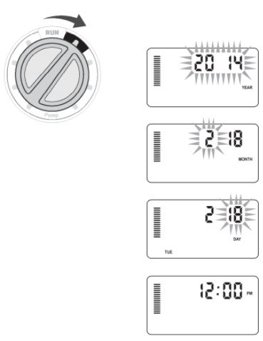
SETTING THE CURRENT DATE AND TIME
- Turn the dial to the DATE/TIME position.
- The current year will be flashing in the display. Use the + and – buttons to change the year. Push the→button to proceed to setting the month.
- The month will be flashing. Use the + and – buttons to change the month. Press the →button to proceed to setting the day.
- The day will be flashing. Use the + and – buttons to change the day of the month. Press the →button to proceed to setting the time.
- The time will be displayed: Use the + and-buttons to select AM, PM, or 24 hr. Press the →button to move to hours. Use the + and – buttons to change the hour shown on the display. Press the →button to move onto the minutes. Use the +and – buttons to change the minutes shown in the display.
The date and time have now been set.
SETTING PROGRAM START TIMES
- Turn the dial to the START TIMES position.
- Press the PRG button to select A, B, or C.
- Use the + and – buttons to change the start time. (Advances in 15-minute increments.) One start time will activate all stations sequentially in that program. This eliminates the need to enter a start time for each station.
- Press the→button to add another start time, or PRG button for the next program.
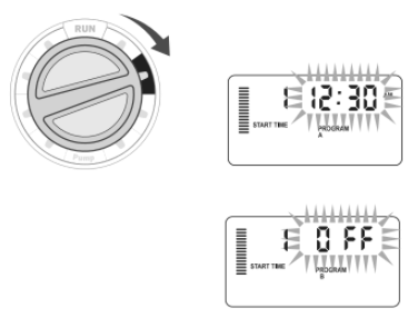
Eliminating a Program Start Time
With the dial set to the START TIMES position, push the + and – buttons until you reach 12:00 am (Midnight). From this position push the – button once to reach the “OFF” position.
NOTE: All stations operate in numerical order. Only one program start time is required to activate a watering program. If a program has all four start times turned off, then that program is off (all other program details are retained). Because there are no start times, there will be no watering with that program.
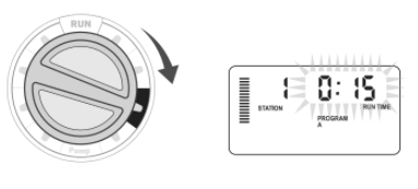
SETTING STATION RUN TIMES
- Turn the dial to the RUN TIMES position.
- The display will show the last program selected (A, B, or C) the station number selected, and the run time for that station will be flashing. You can switch to another program by pressing the PRG button.
- Use the + and – buttons to change the station run time on the display. You may set station run times from 1 minute to 6 hours.
- Press the→button to advance to the next station.
- Repeat steps 2 and 3 for each station.
SETTING A WATERING SCHEDULE
- Turn the dial to the WATER DAYS position.
- The display will show the last program selected (A, B, or C). You can switch to another program by pressing the PRG button.
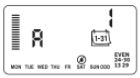
- The controller displays currently programmed active day schedule information. You can choose to water on specific days of the week, or you can choose interval watering, or choose to water on odd days or even days. Each program can operate using only one type of water day option.
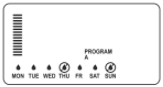
Selecting Specific Days of the Week to Water
- Press the + button to activate a particular day of the week to water (the display always starts with Monday). Press the – button to cancel watering for that day. After pressing a button, the display automatically advances to the next day. A icon indicates awater day. A icon indicates a no water day.
2. After programming, set the dial to the RUN position to enable automatic execution of all selected programs and start times.
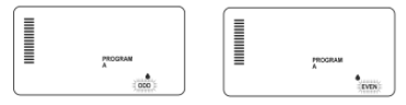
Selecting Odd or Even Days to Water
This feature uses numbered day(s) of the month for watering instead of specific days of the week (odd days: 1st, 3rd, 5th, etc.; even days: 2nd, 4th, 6th, etc.)
- With the cursor on SUN in specific days of the week mode press the → button once. ODD will flash on the screen.
- If even day watering is desired, press the – button once. EVEN will flash on the screen. You can move back and forth from ODD to EVEN by pressing the – button.
- Once you selected odd or even day watering, turn the dial back to the RUN TIMES position.
NOTE: The 31st of any month and February 29th are always “OFF” days if Odd day watering is selected.
Selecting Interval Watering
This feature is convenient if you want to have a more consistent watering schedule without having to worry about the day of the week or the date. The interval you select is the amount of days between watering including the watering day.
- Turn the dial to the WATER DAYS position. The water drop above Monday should be flashing.
- Press the → button until EVEN is flashing, then press the → button one more time. The display will change to the interval mode and the Interval Day number will be flashing.
- Press the + button. The display will now show two numbers: The interval, and the days remaining in the interval.
- The number of days between waterings, or the interval, will be flashing. Use the + and – buttons to select the number of days desired between waterings.
- Press the→button. The days remaining in the interval are now flashing. Use the + and – buttons to select the number of days until the next desired watering. One day remaining means it will water the next day.
NOTE: If any days are selected as non- water days at the bottom of the display, the Interval Day watering will exclude those days. For example, if the Interval Days are set at 5 and Monday is a non- water day, the controller will water every 5th day, but never on a Monday. If the interval water day falls on a Monday and Monday is a non-water day, the program would not water for 5 more days resulting in no irrigation for 10 days total.
OPTIONS FOR RUNNING YOUR IRRIGATION SYSTEM
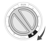
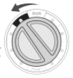
Run
After programming is complete, turn the dial to the RUN position to enable automatic execution of all selected programs and start times.

System Off
Valves currently watering will be shut off after the dial is turned to the SYSTEM OFF position for two seconds. All active programs are discontinued and watering is stopped.
To return controller to normal automatic operation, simply return dial to the RUN position.
Manually Run a Single Station
- Turn the dial to the MANUAL position.

2. Station run time will flash in the display. Use the → button to move to the desired station. You may then use the + and – buttons to select the amount of time
for a station to water.
3. Turn the dial to the RUN position to run the station (only the designated station will water, then controller will return to automatic mode with no change in the
previously set program).
NOTE : The Manual single station function ignores any attached sensor and will allow watering to occur.
Seasonal Adjustment
Seasonal Adjust is used to make global run time changes without re- programming the entire controller. This feature is perfect for making small changes that are necessary as the weather changes. For instance, hotter times of the year may require a bit more water. Seasonal adjust can be increased so that the stations will run longer than the programmed time. Conversely, as fall approaches, the seasonal adjust can be reduced to allow for short watering durations.
- Turn the dial to the SEASONAL ADJUST position.
- Press the + or – buttons to set the percentage desired from 5 percent to 300 percent.
To view the new adjusted run time, turn the dial to set run time’s position. The displayed run times will be updated accordingly as the seasonal adjustment
is made.

NOTE: The controller should always be initially programmed in the 100% position.
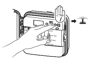
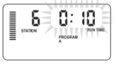
One – Touch Manual Start and Advance
You can also activate a program to water without using the dial.
- With the dial in the RUN position, hold down the → button for 2 seconds.
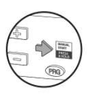
2. This feature automatically defaults to program A. You can select program B, or C by pressing the PRG program.
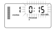
3. The station number will flash. Press the ← or → button to scroll through the stations and use the + and – buttons to adjust the station run times. (If no buttons are pressed during step 2 or 3, the controller will automatically begin program A.)
4. Press the →button to scroll to the desired station to start with. After a 2-second pause, the program will begin.
This feature is great for a quick cycle when extra watering is needed or if you would like to scroll through the stations to inspect your system.
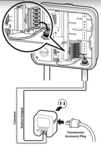
USING THE PRO-C TO OPERATE OUTDOOR LIGHTING (OPTIONAL)
Connecting the FX Luminaire Transformer
The Pro-C is capable of operating three separate lighting transformers equipped with the PXSync interface box.
Connect wires from the first PXSync box to station output 1 (and the Common) on the Pro-C terminal. If using a second or third transformer, the second will be wired to station 2 and the third wil be wired to station 3.
NOTE: Manual cycles initiated at the controller or from a remote will cancel any automatic program currently running. Once manual cycle is complete, the controller will return to automatic mode, and run the next scheduled program at its specified start time
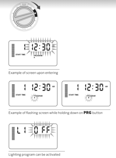
Creating a Lighting Program
- Turn the dial to the START TIMES position.
- Press and hold the PRG button for 6 seconds and observe the A, B, C programs moving.
- L1 and a flashing “OFF” will appear, and the controller is ready to designate lighting programs.
- Add a start time to lighting program L1 by pressing the + and – buttons until the correct time is shown. Up to four start times can be assigned to L1.
- Turn the dial to the RUN TIMES position. Press the PRG button repeatedly until L1 is shown. Use the + and – buttons to add a run time to lighting program L1.
When using a second or third lighting transformer, repeat the same steps above after connecting the additional PXSync boxes, adding start and run times accordingly.
You do not need to program days of the week for lighting programs. They can run every day according to the programmed start and run times.
ADVANCED FEATURES
Set Pump/Master Valve Operation
The default is for all stations to have the master valve/pump start circuit ON.
The master valve/pump start can be set ON or OFF by station, regardless of which program the station is assigned.
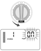
To program pump operation:
- Turn the dial to the PUMP position.
- Press the + or – buttons to toggle the master valve/pump start ON or OFF for the specific station.
- Press the→button to advance to the next station.
- Repeat steps 2 and 3 for all necessary stations.
Programmable Rain Off
This feature permits the user to stop all programmed waterings for a designated period from 1 to 31 days. At the end of the programmable rain off period, the controller will resume normal automatic operation.

- Turn the dial to the SYSTEM OFF position.

2. Press the + button and a 1 will be displayed and the DAYS LEFT icon will illuminate.
3. Press + as many times as needed to set the number of days off desired (up to 31).
- Turn the dial back to the RUN position, at which time, OFF, a number and the DAYS icon all remain on.

5. Leave the dial in the RUN position.

The days off remaining will decrease at idnight of each day. When it goes to zero, the display will show the normal time of day and normal irrigation will
resume at the next scheduled start time.
Setting Specific Day(s) Off
Programming a No Water Day(s) is useful to inhibit watering on mowing days, etc. For instance, if you always mow the lawn on Saturdays, you would designate Saturday as a No Water Day so you are not mowing wet grass.

- Turn the dial to the WATER DAYS position.
- Enter an interval watering schedule as described on page 28.
- Press the → button once. MON will be flashing.
- Use the → button until the cursor is at the day of the week you wish to set as a No Water Day.
- Press the – button to set this day as a no water day. The will illuminate over this day.
- Repeat steps 4 and 5 until all desired event day(s) are off.
HIDDEN FEATURES
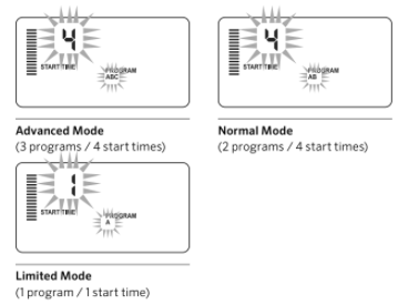
Program Customization
The Pro-C is factory-configured with 3 independent programs (A, B, C with four start times each) for different plant type requirements. The Pro-C can be customized to display only the required programs. You can hide those programs that are not required to ease programming.
- Start with the dial in the RUN position.
- Press and hold the – button. Turn the dial to the WATER DAYS position.
- Release the – buttons.
- Use the + and – button to change program modes.
Programmable Delay Between Stations
This feature allows the user to insert a delay between when one station turns off and the next station turns on. This is very helpful on systems with slow closing valves or on pump systems that are operating near maximum flow or have slow well recovery.
- Start with the dial in the RUN position.
- Press and hold the – button while turning the dial to the RUN TIMES position.
- Release the – button. The display will show a delay time for all stations in seconds.
4. Press the + and – buttons to increase or decrease the delay time between 0 and 59 seconds in 1-second increments and then in 1-minute increments up to 4 hours. Hr will be displayed when the delay changes from seconds to minutes and hours. Maximum delay is 4 hours.
5. Return the dial to the RUN position.
NOTE: The Master Valve/Pump Start circuit will operate during the first 15 seconds of any programmed delay to aid in the closing of the valve and to
avoid unnecessary cycling of the pump.
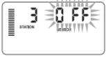
Programmable Sensor Override
The Pro-C allows the user to program the controller so that the sensor disables watering on only desired stations. For example, patio gardens that have pots under overhangs and roofs may not receive water when it rains and will continue to need to be watered during periods of rain. To program sensor override:
- Turn the dial to the RUN position.
- Press and hold the- button while turning the dial to the START TIMES position.
- Release the – button. The display will show the station number, the SENSOR icon, and ON will be flashing.
4. Press the + or – button to enable or disable the sensor for the station shown.
ON = Sensor enabled (will suspend irrigation)
OFF = Sensor disabled (will allow watering)
5. Use the ←or → buttons to scroll to the next station that you would like to program the sensor override.
A station that is running in the sensor override mode will display the word “SENSOR” and flash the icon.
NOTE: The controller default is for the sensor to disable watering on all zones when rain occurs.
Total Run Time Calculator
The Pro-C keeps a running total of each program’s station run times. This feature provides a quick way to determine how long each program will water.
- While in the RUN TIMES mode use the → button to advance to the highest station position.
- Press the →button once to review the total of all run times programmed.
- Use the PRG button to review additional programs.
Test Program
The Pro-C offers users a simplified method for running a test program. This feature operates each station in numerical sequence, from the lowest to the highest. You can start with any station. This is a great feature to check the operation of your irrigation system.
To initiate the test program:
- Press and hold the PRG button. The station number will be flashing.
- Press the ← or→ button to scroll to the station you would like the test program to start with. Use the + and – button to set a run time of up to 15 minutes. The run time needs to be entered only once.
- After a 2-second pause, the test program will begin.
Easy RetrieveTM Program Memory
The Pro-C is capable of saving the preferred watering program into memory for retrieval at a later time. This feature allows for a quick way of resetting the controller to the original programmed watering schedule.
To save the program into memory:
- With the dial in the RUN position, press and hold the + and PRG buttons for 3 seconds. The display will scroll from left to right across the display indicating the program is being saved into memory.
- Release the + and PRG buttons.
To retrieve a program that was previously saved into memory:
- With the dial in the RUN position, press and hold the – and PRGbuttons for 3 seconds. The display will scroll from right to left across the display indicating the program is being retrieved from memory.
- Release the – and PRG buttons.
Solar Sync Delay for Pro-C
The delay feature is accessible only after the installation of the Solar Sync. The Solar Sync Delay feature allows the user to postpone seasonal adjustment changes from being made by Solar Sync for up to 99 days.
While the Solar Sync Delay is active, the Solar Sync will continue to collect and store data.
Operation:
To access the Solar Sync Delay setting:
- Place the dial in the RUN position; press and hold the + button, rotate the dial to the Solar Sync position then release the + button. The following screen will be presented: d:XX (where dindicates days and XX indicates the number of days to be delayed).
- Press the + or – button to increase/decrease the number of days the delay should run. Once the desired number of days is displayed, move the dial back to the RUN position to activate the delay.
To change the existing Delay days setting:
- Open the Solar Sync Delay menu by pressing the + button and rotating the dial to Solar Sync Settings and release the + button.
- Use the + or – keys to modify the number of days until desired numbers of delay days is displayed. (Setting the days to 00 turns Solar Sync Delay to OFF.)
- Return the dial to the RUN position for the changes to take effect.
While Solar Sync Delay is active, the Solar Sync will continue to gather weather information and calculate the Seasonal Adjust Value. The updated seasonal adjust will be applied once the Solar Sync Delay days reach 00.
NOTE: The number of days remaining will not be displayed on the RUN screen. To check if the Delay feature is active, open the Solar Sync Delay menu and check the days displayed. If 1 or more days are displayed, then Solar Sync Delay is active; if 00 is displayed, then Solar Sync Delay is not active.
Cycle and Soak
The Cycle and Soak feature allows you to split a station’s run time into more usable, shorter watering durations. This feature is useful when applying water to slopes and tight soils because it automatically applies water more slowly, helping to prevent runoff from occurring. You should enter the Cycle time as a fraction of the station’s watering time, and the Soak time as the minimum number of minutes required before watering can occur again for the next Cycle. The total number of cycles is determined by taking the total programmed station run time and dividing it by the Cycle time.
Accessing the Cycle and Soak Menu:
The Cycle and Soak feature is accessed by placing the dial in the RUN position, pressing and holding the + button for 3 seconds; while holding the + button rotate the dial to the RUN TIME dial position, then release the button.
Setting the Cycle Time:
Initially Station 1 will be displayed. To access other stations, press the ← or → button.
Once the desired station is displayed, use the + or – button to increase or decrease the Cycle time. The user can set the time from 1 minute to 4 hours in 1-minute increments or to OFF if no Cycle is desired.
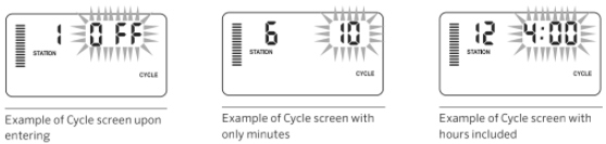
NOTE: Before 1 hour, only minutes are displayed (e.g., 36). At 1 hour or above, the display will change to include the hour digit (e.g., 1:13 and 4:00).
If a station’s Run Time is less than or equal to the Cycle time, then no Cycle will be applied.
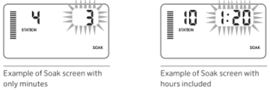
Accessing the Soak Menu:
Once the desired Cycle times for each station have been programmed, the Cycle time can be accessed by pressing the PRG button.
The station will remain the same as was previously displayed under the Cycle time (i.e., if station 2 is displayed in the Cycle menu then Station 2 will be displayed upon pressing the PRG button).
NOTE: The Soak menu cannot be accessed without a programmed Cycle time.
Setting the Soak Time:
To access the other stations, press the ← or→button.
NOTE: When changing the stations, if a station without a Cycle time is encountered, the screen will revert back to the Cycle time. Move to the next station
with a Cycle Time and press the PRG button to return.
Once the desired station is displayed, the user can use the + or – button to increase or decrease the Soak time. The user can set the Soak time from 1 minute to 4 hours in 1-minute increments.
NOTE: Before 1 hour, only minutes are displayed (e.g., 36). At 1 hour or above, the display will change to include the hour digit (e.g., 1:13 and 4:00).
Cycle and Soak Situations:
Station 1 requires 20 minutes of watering, but after 5 minutes, runoff occurs. However, after 10 minutes all the water is absorbed. The solution would be to program 20 minutes for the station run time, 5 minutes for the Cycle time, and 10 minutes for the Soak time.
The soak time is a minimum amount. The soak time may be longer amount depending on the remaining run times.
Hunter Quick CheckTM
This circuit diagnostic procedure can quickly identify “shorts” commonly caused by faulty solenoids or when a bare common wire touches a bare station control wire.
To initiate the Hunter Quick Check test procedure:
- Press the +, -, ← and→ buttons simultaneously. In the standby mode, the LCD will display all segments (helpful when troubleshooting display problems).
- Press the + button to begin the Quick Check test procedure.
The system will search all stations to detect a high current path through the station terminals. When a field wiring short is detected, an ERR symbol preceded by the station number will momentarily flash on the controller LCD display. After the Hunter Quick Check completes running this circuit diagnostic procedure, the controller returns to the automatic watering mode.
Clearing Controller’s Memory/Resetting Controller
If you feel that you have misprogrammed the controller, there is a process that will reset the memory to factory defaults and erase all programs and data that have been entered into the controller. Press and hold the PRG button. Press and release the RESET button on the back of the front panel. Wait until the
display shows 12:00 am. Release the PRG button. The controller is now ready to be reprogrammed.
NOTE: Any programs that have been saved with Easy Retrieve will remain after resetting controller.
WINTERIZING YOUR SYSTEM
In regions where the frost level falls below the depth of the installed piping, it is common for systems to be “winterized.”
Several methods can be used to drain the water from the system. If compressed air method is used, we recommend that a qualified licensed contractor perform this type of winterization.
NOTE: WARNING! WEAR ANSI- APPROVED SAFETY EYE PROTECTION! Extreme care must always be taken when blowing out the system with compressed air. Compressed air can cause serious injury, including serious eye injury from flying debris. Always wear ANSI-approved safety eye protection and do not stand over any irrigation components (pipes, sprinklers, and valves) during blowout. SERIOUS PERSONAL INJURY MAY RESULT IF YOU DO NOT PROCEED AS RECOMMENDED.
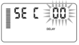
CLIK DELAY INSTRUCTIONS
Clik Delay Feature
This feature allows the user to delay programmed waterings for a designated period (from 1-7 days) AFTER a Clik Event ends.
At the end of Programmed Clik Delay period, the controller will resume normal automatic irrigation.
- Turn the dial to the RUN Position
- Press and hold the “+” button for 3 seconds, then turn the dial to the OFF position
- Release the “+” button. The display will show the programmable Clik Delay.

- Press the “+” button to set Clik Delay duration (from 1 to 7 days).
- Return the dial to the RUN position. Clik Delay is set.
After a Clik Event ends (rain sensor changes from wet to dry) the Clik Delay feature will become active and the screen will display Clik Delay duration. The day count down will occur 24 hours after the start of Clik Delay.

An active Clik Delay can be cancelled by turning the dial to the OFF position, waiting for OFF to stop flashing, then turning the dial back to the RUN position.
Any station that is set to override sensor, as well as Lighting Programs, will operate during a Clik Delay event.
Note: Use caution when using the programmable Clik Delay feature with Hunter Wind-Clik, Freeze-Clik, Soil- Clik, and freeze component of Solar Sync and
Rain/Freeze Clik as the Clik Delay will become active AFTER Clik Event from these devices.
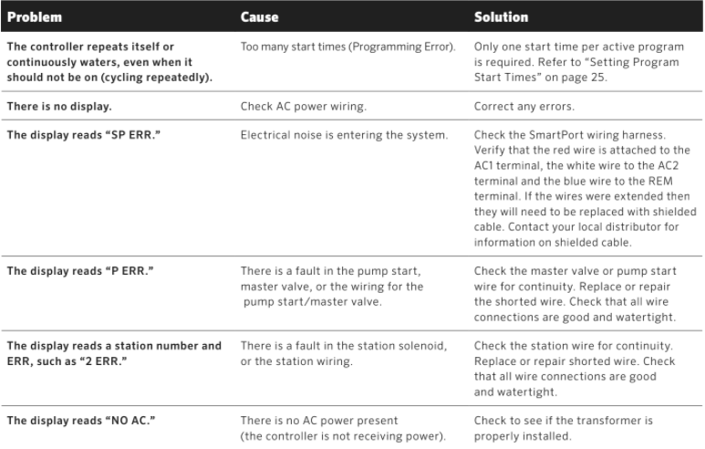
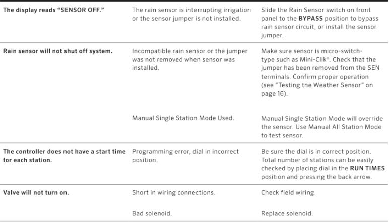
TROUBLESHOOTING GUIDE
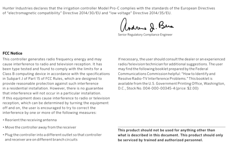
Certificate of Conformity to European Directives
You can download the PDF version of the Homer OM PRO-C® Residential and Light Commercial Irrigation Controller User Manual here.