
IF YOU SHOULD EXPERIENCE A PROBLEM WITH YOUR DEWALT PURCHASE, Before returning this product CALL 1-800-4 DEWALT. IN MOST CASES, A DEWALT REPRESENTIVE CAN RESOLVE YOUR PROBLEM OVER THE PHONE. IF YOU HAVE A SUGGESTION OR COMMENT, GIVE US A CALL. YOUR FEEDBACK IS VITAL TO THE SUCCESS OF DEWALT’S QUALITY IMPROVEMENT PROGRAM.
Questions? See us in the World Wide Web at www.dewalt.com
DEWALT
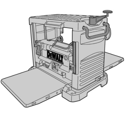
DW733 12-1/2″ (318 mm) Heavy Duty Portable Thickness Planer
IF YOU HAVE ANY QUESTIONS OR COMMENTS ABOUT THIS OR ANY DEWALT TOOL, CALL US TOLL FREE AT: 1–800–4–DEWALT (1–800–433–9258)
DEWALT... BUILT JOBSITE TOUGH DEWALT high performance industrial tools are made for America’s toughest industrial and construction applications. The design of every tool in the line – from drills to sanders to grinders – is the result of rigorous use on jobsites and throughout industry. Each tool is produced with painstaking precision using advanced manufacturing systems and intense quality control. Every tool is checked before it leaves the factory to make sure that it meets your standards for durability, reliability and power. DEWALT Built Jobsite Tough…WE GUARANTEE IT.
Important Safety Instructions (For all tools)
A WARNING: When using electric tools, basic safety precautions should always be followed to reduce risk of fire, electric shock, and personal injury, including the following: AWARNING: FOR YOUR OWN SAFETY READ INSTRUCTION MANUAL BEFORE OPERATING TOOL.
Grounding Instructions
In the event of a malfunction or breakdown, grounding provides a path of least resistance for electric current to reduce the risk of electric shock. This tool is equipped with an electric cord having an equipment-grounding conductor and grounding plug. The plug must be plugged into a machine outlet that is properly installed and grounded in accordance with all local codes and ordinances. Do not modify plug provided—if it will not fit the outlet, have the proper outlet installed by a qualified electrician.
Improper connection of the equipment-grounding conductor can result in a risk of electric shock. The conductor with insulation having an outer surface that is green with or without yellow stripes is the equipment-grounding conductor. If repair or replacement of the electric cord or plug is necessary, do not connect the equipment-grounding conductor to a live terminal.
Check with a qualified electrician or service personnel if the grounding instructions are not completely understood, or if in doubt as to whether the tool is properly grounded. Use only 3-wire extension cords that have 3-prong grounding plugs and 3-pole receptacles that accept the tool’s plug. Repair or replace damaged or worn cords immediately.
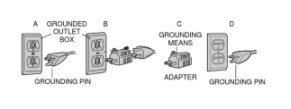
Grounded, cord-connected tools intended for use on a supply circuit having a nominal rating less than 150 volts: This tool is intended for use on a circuit that has an outlet that looks like the one illustrated in Figure A. The tool has a grounding plug that looks like the plug illustrated in Figure A. A temporary adapter, which looks the adapter illustrated in Figures B and C, may be used to connect this plug to a 2-pole receptacle as shown in Figure B if a properly grounded outlet is not available. The temporary adapter should be used only until a properly grounded outlet can be installed by a qualified electrician. The green-colored rigid ear, lug, and the like, extending from the adapter must be connected to a permanent ground such as a properly grounded outlet box.
Grounded, cord-connected tools intended for use on a supply circuit having a nominal rating between 150–200 volts, inclusive: This tool is intended for use on a circuit that has an outlet that looks like the one illustrated in Figure D. The tool has a grounding plug that looks like the plug illustrated in Figure D. Make sure the tool is connected to an outlet having the same configuration as the plug. No adapter is available or should be used with this tool. If the tool must be reconnected for use on a different type of electric circuit, the reconnection should be made by qualified service personnel; and after reconnection, the tool should comply with all local codes and ordinances.
Permanently connected tools: This tool should be connected to a grounding metal permanent wiring system, or to a system having an equipment-grounding conductor.
Important Safety Instructions
- KEEP GUARDS IN PLACE and in working order.
- REMOVE ADJUSTING KEYS AND WRENCHES. Form habit of checking to see that keys and adjusting wrenches are removed from tool before turning it on.
- KEEP WORK AREA CLEAN. Cluttered areas and benched invite injuries.
- DON’T USE IN DANGEROUS ENVIRONMENT. Don’t use power tools in damp or wet locations, or expose them to rain. Keep work area well lighted.
- KEEP CHILDREN AWAY. All visitors should be kept safe distance from work area.
- MAKE WORKSHOP KID PROOF with padlocks, master switches, or by removing starter keys.
- DON’T FORCE TOOL. It will do the job better and safer at the rate for which it was designed.
- USE RIGHT TOOL. Don’t force tool or attachment to do a job for which it was not designed.
- USE PROPER EXTENSION CORD. Make sure your extension cord is in good condition. When using and extension cord, be sure to use one heavy enough to carry the current your product will draw. An undersized cord will cause a drop in line voltage resulting in loss of power and overheating. The following table shows the correct size to use depending on cord length and nameplate ampere rating. If in doubt, use the next heavier gage. The smaller the gage number, the heavier the cord.

- WEAR PROPER APPAREL. Do not wear loose clothing, gloves, neckties, rings, bracelets, or other jewelry which may get caught in moving parts. Nonslip footwear is recommended. Wear protective hair covering to contain long hair.
- ALWAYS USE SAFETY GLASSES. Also use face or dust mask it cutting operation is dusty. Everyday eyeglasses only have impact resistant lenses, they are not safety glasses.
- DON’T OVERREACH. Keep proper footing and balance at all times.
- MAINTAIN TOOLS WITH CARE. Keep tools sharp and clean for best and safest performance. Follow instructions for lubricating and changing accessories. DISCONNECT TOOLS before servicing; when changing accessories, such as blades, bits, cutters, and the like.
- REDUCE THE RISK OF UNINTENTIONAL STARTING. Make sure switch is in off position before plugging in.
- USE RECOMMENDED ACCESSORIES. Consult the instruction manual for recommended accessories. The use of improper accessories may cause risk of injury to persons.
- NEVER STAND ON TOOL. Serious injury could occur if the tool is tipped or if the cutting tool is unintentionally contacted.
- CHECK DAMAGED PARTS. Before further use of the tool, a guard or other part that is damaged should be carefully checked to determine that it will operate properly and perform its intended function-check for alignment of moving parts, binding of moving parts, breakage of parts, mounting, and any other conditions that may affect its operation. A guard or other part that is damaged should be properly repaired or replaced.
- DIRECTION OF FEED. Feed work into planer according to direction of feed arrows on top of the unit.
- NEVER LEAVE TOOL RUNNING UN ATTENDED. TURN POWER OFF. Don’t leave tool until it comes to a complete stop.
Additional Safety Rules for Planers
- To reduce the risk of injury, user must read and understand instruction manual before operating planer.
- Always wear eye protection and dust mask if necessary.
- Keep hands 6″ away from motor carriage when feeding work piece.
- Never make cutter knife replacement or any other repairs/adjustments with unit plugged in.
- Make certain that the switch is in the off position before connecting plug to a power source.
- Be sure that the cutter knives are mounted as described in the instruction manual and check that all bolts are firmly tightened before connecting unit to power source.
- To avoid injury, never rotate the cutter block directly with your hands.
- Keep guards in place and in good working order.
- Stay alert- never operate the unit when tired or under the influence of drugs, alcohol, or medication. Do not use in dangerous environments.
- Do not use near flammable substances, in damp or wet locations, or expose to rain.
- Never plane material which is shorter than 12 inches.
- Do not wear gloves, neckties, jewelry, or loose clothing.
- Some wood contains preservatives such as copper chromium arsenate (cca) which can be toxic. When planning these materials extra care should be taken to avoid inhalation and minimize skin contact.
- Exhaust chute: remove shavings with brush or vacuum after power has been shut off and cutter head has stopped rotating.
- ALWAYS LOCATE PLANER WITH PROPER CLEARANCE ON THE OUTFEED SIDE of the unit to prevent pinching or binding of the workpiece or any other obstacle.
WARNING: Some dust created by power sanding, sawing, grinding, drilling, and other construction activities contains chemicals known to cause cancer, birth defects or other reproductive harm. Some examples of these chemicals are:
• lead from lead–based paints,
• crystalline silica from bricks and cement and other masonry products, and
• arsenic and chromium from chemically-treated lumber (CCA).
Your risk from these exposures varies, depending on how often you do this type of work. To reduce your exposure to these chemicals: work in a well ventilated area, and work with approved safety equipment, such as those dust masks that are specially designed to filter out microscopic particles.
SAVE THESE INSTRUCTIONS
Specifications
- Input ………….. .120V AC, 15 Amp
- No-load speed ….10,000 RPM
- Feed speed…… .26 ft. per minute
- Planing height ….. . Maximum 6″, Minimum 1/8″
- Planing width ………… Maximum 12-1/2″
- Planing depth ………. Maximum 1/8″ (for boards 5 1/2″ wide or less)
Electrical Connection
Be sure your power supply agrees with the nameplate marking. AC ONLY means that your planer will operate on alternating current only. A voltage decrease of 10 percent or more will cause a loss of power and overheating. All DEWALT tools are factory tested. If this tool does not operate, check the power supply.
Familiarization
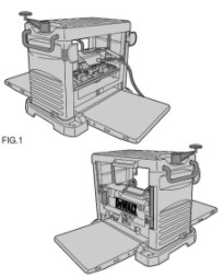
Except for the depth adjustment handle, our planer is fully assembled in the carton. See Figure 1.
Unpacking Your Planer
Check the contents of your planer carton to make sure that you have received all parts. In addition to this instruction manual, the carton should contain:
- 1 allen wrench
- 1 L-shaped bolt wrench
- 1 open-ended wrench (10mm/8mm)
- 2 magnetic knife gauges
- 1 Depth adjustment handle
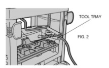
- 1 Allen screw These tools are located in the tray on the back side of your planer, as shown in Figure 2.
Attaching Depth Adjustment Handle
Using the allen screw provided, attach the depth adjustment handle as shown in figure 9.
Bench Mounting
Holes are provided on the four corners of your planer to facilitate bench mounting, as shown in Figure 3. (Two different sized holes are provided. If mounting the planer with bolts, use the larger holes. If mounting the planer with nails or screws, use the smaller holes. Use either size hole; it is not necessary to use both.) Always mount your planer firmly to prevent movement. To enhance the tool’s portability, it can be mounted to a piece of 1/2″ (12.7mm) or thicker plywood which can then be clamped to your work support or moved to other job sites and reclamped.
NOTE: If you elect to mount your planer to a piece of plywood, make sure that the mounting screws don’t protrude from the bottom of the wood. The plywood must sit flush on the work support.
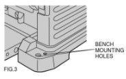
A CAUTION: Be sure the mounting surface is not warped or otherwise uneven.
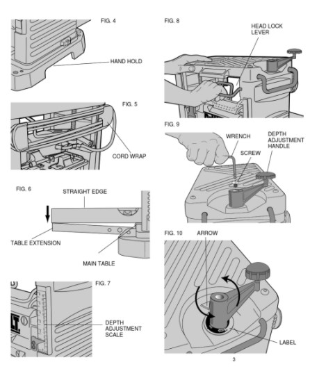
Transporting the planer
When moving your planer, carry it either by the side carrying handles or by the hand indentation at the base of the planer. (Figure 4). When transporting or storing the planer, use the cord wrap located in the back of the tool (Figure 5) to keep the cord in-place.
Operating Controls
Table Extensions
Before using your planer, fold down the table extensions in the front and back of the tool. The back edge of each table extension is adjusted to be level with main table (Figure 6). After extended use, the table extensions might become slightly out of level. See the Adjustments section of this manual for levelling directions.
Depth Adjustment
DEPTH ADJUSTMENT SCALE
The depth adjustment scale, located on the right front of your planer, indicates the finished thickness of your workpiece (Figure 7).
DEPTH ADJUSTMENT HANDLE
To set the finished thickness, first unlock the head lock lever (Figure 8). This allows the cutting head to be easily adjusted. Re-lock the head lock lever before planing for best results.
Turning the handle clockwise lowers the cutting head, while turning counter-clockwise raises the cutting head. One full rotation of the handle moves the cutter head 1/16″.
FINE ADJUSTMENTS
The depth adjustment handle also allows for fine adjustments, from 1/64″ to 1/16″. Fine adjustments are ideal for “shaving” small amounts from planed material. For example, if your planed workpiece measures 3 1/16″ thick, but should be 3″ thick, adjust your planer to remove the excess 1/16″:
- Plane and measure your workpiece. In this example, the finished thickness is 3 1/16″.
- Turn the circular label on the depth adjustment handle until the “O” mark aligns with the arrow on the top of the tool (Figure 10). Do not make any other adjustments to the planer.
- Turn the depth adjustment handle clockwise until the 1/16″ mark aligns with the arrow.
- Plane your workpiece. The final thickness should be 3″.
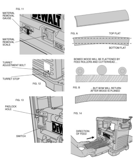
MATERIAL REMOVAL SCALE
Your planer is equipped with a material removal scale, which indicates the amount of wood being removed in a planing operation. (Fig. 11 ) Ensure the workpiece is under the material removal gauge label on the front of the tool. The material removal gauge readout is to the right of this label.
TURRET STOP
Your planer is equipped with a turret stop (Fig. 12) for repetitive planing of pre-set depths. Stops are set at 0″, 1/4″, 1/2″ and 3/4″. Use the 0″ setting when planing between 1/8″ and 1/4″. To set a planing depth using the turret stop:
- • Turn the turret stop until the desired measurement shows (Figure 12).
- • Unlock the headlock lever, and turn the depth adjustment lever clockwise until it contacts the turret stop. Do not turn the handle past its stopping point.
- • Plane the workpiece and measure the finished thickness. Make fine adjustments if necessary. The 3/4″ turret stop can be adjusted for other planing thicknesses. Adjusting the 3/4″ turret stop does not affect the other turret stop settings. To adjust the 3/4″ stop for other thicknesses:
- • Unlock the head lock lever (Fig. 8) and turn the adjustment handle counter-clockwise to raise the cutting head (Fig. 9) fully. . From the back of the tool, locate the turret adjustment bolt shown in Fig. 12. This bolt is set for a 3/4″ depth of cut at the factory. Loosen the jam nut and adjust the bolt up or down to reach the desired planing depth.
- • Turn the depth adjustment lever clockwise until it contacts the turret stop. Do not turn the handle past its stopping point.
- • Plane your workpiece and measure its finished thickness. Make additional adjustments, if necessary, following the steps above.
NOTE: For best results, make several passes, planing both sides of the workpiece. See “Proper Planing Technique” below.
On/Off Switch
To turn the planer on, flip up the switch, as shown in Figure 13. The planer locks on automatically. To turn the tool off, press the switch down. A hole is provided in the switch for insertion of a padlock to lock off the planer (Figure 13).
Proper Planing Technique
A WARNING: Plane only wood that is free from foreign objects, with no loose knots and as few tight knots as possible. Do not plane wood that is severely warped, twisted, knotted or bowed.
Your planer works best on lumber with at least one flat surface. If both sides of your workpiece are rough, use a jointer to level one surface.
For best results, plane both sides of the workpiece to reach a desired thickness. For example, if you need to remove 1/8″ from your workpiece, remove 1/16″ from each side. This not only allows the workpiece to dry with a even moisture content, it also produces finer cuts.
NOTE: Planing material less than 3/4″ wide is not recommended. If you must plane narrow material, gang up the pieces and plane them as one wider workpiece, if possible. Support the work piece adequately at all times. The maximum depth of cut your planer can take is 1/8.” Never attempt to modify your planer to take a deeper cut. Follow the depth of cut and width guidelines shown in Table A for best results.
SNIPE
Snipe is a depression made when the ends of the workpiece contact the cutterhead knives. Snipe occurs when the unsupported weight of the workpiece causes it to lift off the table, into the cutterhead. To avoid snipe:
- • Keep workpiece level throughout the planing operation
- • Ensure that the table extensions are level with the main table (See: Levelling the Table Extensions)
- • Feed work flat against the planer tables
WARPING
Warped wood can not only jam the planer, it can produce variations in the final thickness of the workpiece. If your planer becomes jammed, turn off the switch and disconnect the planer from the power supply. If your workpiece is not warped or only slightly warped, plane both sides of the board to produce the desired thickness. Always feed the workpiece in the direction of the grain. Cupped wood is similar to the piece is shown in Figure A. Bowed wood is shown in Figure B.
TO PLANE CUPPED WOOD:
For best results, rip the workpiece down the middle, and plane the pieces separately. This eliminates waste.
If this is not possible, follow the steps below.
- • Plane the top flat first (see Figure A)
- • Turn the board over and plane the bottom flat Bowed wood can be planed with little effect on on finished thickness. The feed rollers and cutterhead in your planer will temporarily flatten the bowed workpiece. However, bowed wood will return to its shaped once planed. To remove the bow, use a jointer.
Planing
After making all adjustments, turn the tool on and wait until the knives reach full speed. The workpiece should not be in contact with the feed rollers or the cutterhead when the tool is switched on. Feed wood into the planer as shown in Figure 14. Do not force wood into the cutterhead. Let the feed rollers determine how fast the wood is planed.
Adjustments Changing Knives
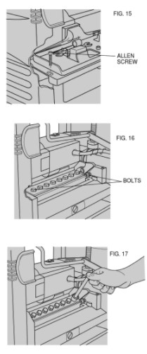
REMOVING KNIVES
Your planer is equipped with two knives attached to a rotating cutterhead. To remove the knives:
- 1) Turn off and unplug planer. Lift the headlock lever to the up, or unlocked position.
- 2) Adjust the depth of cut until the scale reads about 3″. This will ensure ample room to change the knives.
- 3) Remove the two allen screws near the tool tray, shown in Figure 15. Carefully lift off the dust chute. CAUTION: Removing the dust chute leaves the knives exposed.
- 4) If the eight bolts shown in Figure 16 are not visible, carefully rotate the cutterhead using a small piece of scrap wood. Keep your fingers away from the cutterhead until the eight bolts are visible.
- 5) When the eight bolts shown in Figure 16 are positioned as shown, ensure the cutterhead lock lever is in its locked position and the cutterhead is stable. The knives will also lock, preventing any further rotation.
- 6) Using the supplied L-shaped wrench, loosen, but do not remove the two end bolts shown in Figure 17.
- 7) Carefully remove the middle six bolts. A WARNING: The knife is spring loaded, and may move toward you when the six bolts are removed.
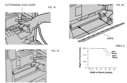
- 8) Press the cutterhead lock lever (Figure 18) down toward the knife and gently roll the cutterhead backward until the knife can be removed.
- 9) Press the cutterhead lock lever (Figure 18) down and roll the cutterhead until the other knife assembly is visible. Remove this knife following the steps above.
REPLACING KNIVES
1) Position the cutterhead as shown in Figure 19.
2) Carefully slide the new knife on to the cutterhead, as shown in Figure 20.
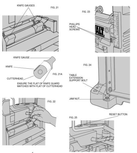
3) Place the two magnetic knife gauges (located in the tool tray) onto the cutterhead as shown in Figure 21. Ensure the flat edge of the knife gauge is in contact with the flat edge of the cutterhead (Figure 21A). This positions the knife properly on the cutterhead.
4) Firmly tighten the the two end bolts, using the open-ended wrench provided, as shown in Figure 22.
5) Remove the knife gauges and rotate the cutterhead back to the position shown in Figure 18. Replace and retighten the six middle bolts. Bolts should be tighten to a torque of 50 in. lbs. (5.7 N-m).
6) Press the cutterhead lock lever (Figure 18) down and roll the cutterhead until the other knife assembly is visible. Replace this knife following the steps above.
SHARPENING KNIVES
Your planer knives have 1/8″ of extra material to allow for resharpening. Ensure the knives are resharpened at the same angle (429). DEWALT replacement blades (Cat No. DW7332) are available at extra cost from your local dealer or authorized service center.
Installing a new belt
1. TURN OFF AND UNPLUG THE PLANER.
2. Remove the two Phillips head screws from the front and back of the right side cover of the planer.
3. Lift the entire cover straight up and pull the bottom out of the slot. NOTE: No tools are necessary to install a belt. The use of a screwdriver or other tool may cause damage to the pulleys and ultimately destroy the new belt.
4. Notice the grooves inside the belt.
5. Figure 27 – Start the belt on the top pulley (A) as shown in Figure 1 with 3 grooves on the pulley.
6. Figure 28 – Guide the belt between the lower pulley and the height adjustment screw (B).
7. With 3 grooves engaged on the large pulley, rotate it in a clockwise direction.
8. Keep pressure on the edge of the belt to keep the grooves engaged on the small pulley.
9. Figure 29 – Continue to keep pressure on the side of the belt and rotate the large pulley while hopping the belt further onto the pulleys.
10.In the final position, all of the belt grooves should be engaged. The pulleys should rotate smoothly 11.Reinstall the side cover and the screws. Do not overtighen the self-tapping screws.
Calibrating the Depth Adjustment Scale
The depth adjustment scale on your planer is set at the factory. However, with extended use, the depth adjustment scale could show an incorrect measurement. To check the depth adjustment scale, plane a piece of wood, noting the measurement on the depth adjustment scale. Measure the finished thickness of the workpiece. If the thickness of the workpiece does not match the reading on the depth adjustment scale, loosen the two phillips head screws shown in Figure 23. Adjust the pointer up or down until its reading matches the finished thickness of the workpiece. Securely re-tighten the screws.
Levelling the Table Extensions
After extended use, the table extensions might become slightly out of level. To ensure that the tables are level, place a straight edge on the table extension. The straight edge should contact the edge of the table extension and the main table (Figure 6). When levelling, press the edge of the table extensions down to remove any play. For best results, use a level long enough to contact the edges of both table extensions. If the table extensions are not level, loosen the jam nuts and adjust the table extension support bolts up or down (Figure 24).
Reset Button
Your planer is equipped with an 18 amp circuit breaker. If your planer becomes overloaded and stops operating, turn off the planer and press in the reset button (Figure 25).
Maintenance BRUSHES
Inspect carbon brushes regularly by unplugging tool, removing the brush inspection cap (Figure 26) and withdrawing the brush assembly. Keep brushes clean and sliding freely in their guides. Always replace a used brush in the same orientation in the holder as it was prior to its removal. Carbon brushes have varying symbols stamped into their sides, and if the brush is worn down to the line closest to the spring, they must be replaced. Use only identical DEWALT brushes. New brush assemblies are available at DEWALT service centers. The tool should be allowed to “run in” (run at no load) for 10 minutes before use to seat new brushes.
TABLE
Keep the table clean and free from oil, grease and pitch. Treat the table with paste wax to help maintain its smooth finish.
Accessories
Recommended accessories for use with your tool are available at extra cost from your distributor or local service center.
CAUTION: The use of any non-recommended accessory may be hazardous.
Important
To assure product SAFETY and RELIABILITY, repairs, maintenance and adjustment (including brush inspection and replacement) should be performed by authorized service centers or other qualified service organizations, always using identical replacement parts.
You can download the PDF version of DEWALT DW 733 USER MANUAL here.