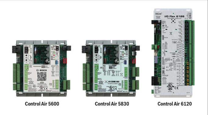
Compatible with DDC Control Air 5600, 5830, and 6120 Controllers
Key to Symbols and Safety Instructions
Key to symbols
Warnings: Warnings in this document are identified by a warning triangle printed against a grey background. Keywords at the start of a warning indicate the type and seriousness of the ensuing risk if measures to prevent the risk are not taken.
The following keywords are defined and can be used in this document:
- DANGER indicates a hazardous situation which, if not avoided, will result in death or serious injury.
- WARNING indicates a hazardous situation which, if not avoided, could result in death or serious injury.
- CAUTION indicates a hazardous situation which, if not avoided, could result in minor to moderate injury.
- NOTICE is used to address practices not related to personal injury.
Important information: This symbol indicates important information where there is no risk to people or property.
Safety
WARNING:
- Improper installation, set-up, modification, operation or maintenance of this product can cause personal injury and property damage.
- Follow these instructions precisely.
- If you require assistance or further information, contact a licensed contractor
Overview
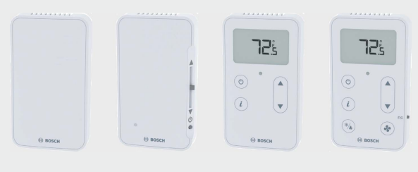
The Bosch line of intelligent zone sensors provides the function and flexibility needed to manage the conditions important to the comfort and productivity of the zone occupants. The ZS series are available in a variety of zone sensing combinations to address most application needs. These combinations include temperature, relative humidity, and carbon dioxide (CO2) for indoor air quality (IAQ) improvement. They are built to be flexible, allowing for easy customization of what the user/ technician sees. Designed to work with the DDC Control Air 5600, 5830, and 6120 controllers1, the ZS sensor line includes the ZS Base, ZS Slidebar, ZS Push, and ZS Manager2.
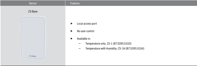
ZS Base

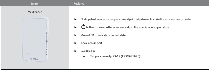
ZS Slidebar

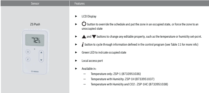
ZS Push
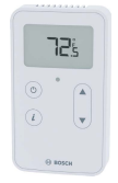
ZSP-1HC
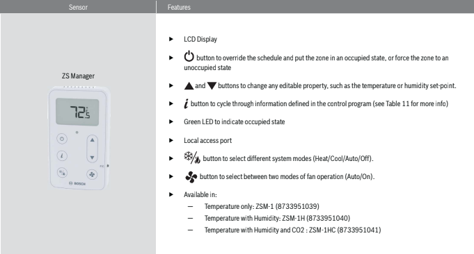
ZS Manager*
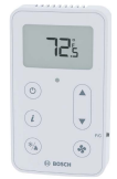
ZSM-1HC
1 Previously known as FHP560, I/O Zone 583, and FLEX 6126 respectively.
2 Previously known as ZS Base, ZS Plus, ZS Pro and ZS Pro-F respectively.
- Available only by special request if ordered in 2018. ** Readout only.
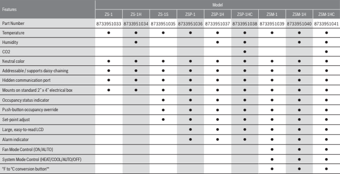
Available Models
| Sensor Model | Description | Bosch Part Number |
| ZS-1 | Base Zone Temperature Sensor, no options | 8733951033 |
| ZS-1H | Base Zone Temperature Sensor, with humidity | 8733951034 |
| ZS-1S | Zone Temperature Sensor with override button, slidebar, occupied LED | 8733951035 |
| ZSP-1 | Zone Temperature Sensor, Push Button with LCD display, no options | 8733951036 |
| ZSP-1H | Zone Temperature Sensor, Push Button with LCD display, with humidity | 8733951037 |
| ZSP-1HC | Zone Temperature Sensor, Push Button with LCD display, with humidity and CO2 | 8733951038 |
| ZSM-1 | Zone Temperature Sensor, Manager with LCD display, no options | 8733951039 |
| ZSM-1H | Zone Temperature Sensor, Manager with LCD display, with humidity | 8733951040 |
| ZSM-1HC | Zone Temperature Sensor, Manager with LCD display, with humidity and CO2 | 8733951041 |
Specifications
| Sensing Element | Range | Accuracy |
| Temperature (On Non-Humidity Models) | -4°F to 122°F (-20° C to 50°C) | ±0.35° F (0.2° C) |
| Temperature (On Humidity Models) | 50° F to 104° F (10° C to 40° C) | ±0.5° F (0.3° C) |
| Humidity | 10% to 90% | ±1.8% typical |
| CO2 | 400 to 1250 PPM 1250 to 2000 PPM | ±30PPM or +/-3% of reading (greater of two) ±5% of reading plus 30 PPM |
| Power Requirements | Sensor Type | Power Required |
| Temperature Only | All Models | 12Vdc @ 8mA |
| Temperature/CO2/ Humidity | All Models | 12 Vdc @ 15 mA (idle) to 190 mA (CO2 measurement cycle) |
Power Supply
A controller supplies the Rnet sensor network with 12 Vdc @ 210 mA.
Additional power may be required depending on the application.
Communication
115 kbps Rnet connection between sensor(s) and controller
5 sensors max per control program (5 sensors can be daisy-chained to one controller for power averaging)
Local Access Port
For connecting a laptop computer to the local equipment for maintenance and commissioning
Environmental Operating Range
32° to 122° F (0° to 50° C), 10% to 90% relative humidity, non-condensing
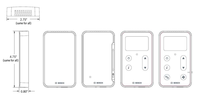
Mounting Dimensions
Standard 2″ x 4″ electrical box using provided 6/ 32″ x 1/2″ mounting screws
Features
The ZS Series Zone Sensors are thermistor-based, communicating temperature sensors that may optionally sense humidity or CO2 . The ZS Sensors are field
installed and are wired to the Rnet port of the DDC Control Air 5600, 5830, or 6120 controller1. A maximum of 5 ZS sensors may be daisy-chained and used for
applications where averaging of multiple readings for temperature is required.
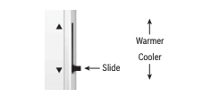
Slide the sensor’s potentiometer up to make the zone warmer or down to make it cooler. The control program determines how much you can adjust the set point.(see figure# 2)
Addressing Sensors
When multiple ZS Series Zone Sensors (up to 5 max) are connected to the DDC controller, each sensor on the Rnet must have a unique address associated with
it, and the addresses have to be sequential. If the sensors are not addressed sequentially the DDC Controller reads any gaps as faulty sensors and a sensor wiring alarm is generated.
The DIP switches located at the back of the sensor (next to the Rnet connector block) may be used to set an address from 1 to 5 (the factory default address for all Bosch branded ZS Series sensors is “1”).
There are four (4) DIP switches (numbered 1 through 4) used to address the ZS Series sensors. Each DIP switch has a value assigned to it for addressing the sensors as shown in the table
| DIP Switch Number | DIP Switch Value |
| 1 | 1 |
| 2 | 2 |
| 3 | 4 |
| 4 | 8 |
Turn on as many DIP switches as needed so that their total value equals the required address. In the example shown in Figure 3, DIP switches #1 and #4 are ON (to the right position). Their values (1 + 8) total 9, so the sensor’s address is 9.
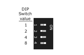
While the DIP switches may be used to address the sensor for any value from 0 to 14, the DDC Control Air 5600, 5830, and 6120 controllers ONLY recognize values from 1 to 5, and any other address will result in the sensor(s) not functioning properly.
Multiple Sensors
Multiple ZS Series Zone Sensors on an Rnet must be configured in the software (using *Control Air M or M+ interface or legacy BACview) in order for the DDC Control Air 5600, 5830, and 6120 to function as required.
Any combination of sensing capabilities may be used (Temperature, Relative Humidity, CO2 ), and the effective temperature value used to control the unit may be configured as the minimum, maximum, or average of all the individual values.
Formatting Sensors
Formatting a sensor clears its flash memory. To format a sensor perform one of the two options below:
- Download the controller that the sensor is connected to with new software using App loader.
OR - Perform the following steps:
a. Remove the wiring connector from the sensor
b. Note the current position of the DIP switches
c. Set all DIP switches to the ON position
d. Reattach the wiring connector to format
e. After approximately 3 seconds, remove the wiring connector
f. Set the DIP switches back to their original position
g. Reattach the wiring connector
ZS Push/Manager Sensors
The ZS Push and Manager Series Sensors can be ordered as temperature only, temperature with relative humidity, or temperature with relative humidity and CO2 . They are the most versatile of the the four sensor models, and are designed to work with the DDC Control Air 5600, 5830, and 6120 controllers.
The ZS Push and Manager Series Sensor allows the user to:
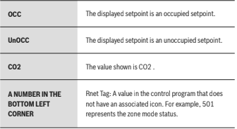
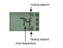
- View information in the display such as zone temperature, setpoints, outside air temperature, and equipment status
- Make the zone warmer or cooler by adjusting the setpoint. By default the DDC Control Air 5600, 5830, or 6120 only allows a temperature change of 3 degrees in either direction (cooler or warmer) but this value can be changed using the Control Air M or M+ interface, legacy BACview, or from the BAS
- Adjust humidity setpoint when unit is equipped with hot gas reheat to control relative humidity in the space
- Override the schedule to put the zone in an occupied state (in increments of 30 minutes with a maximum override time of 3 hours)
- Force the zone to an unoccupied state
- See that the zone is in an occupied state when the green LED is lit.
- Alert residents in plain text of error and fault messages that require specificactions (e.g. change filter required). See Table 13
- See that the fan is running when the fan symbol is displayed on the screen
- Set System and Fan Modes (only on ZS Manager)
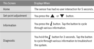
Navigating the Push/Manager Sensor’s Screens
The control program determines what screens you see, what information is in each screen, and what you can adjust. The type of sensor also determines what you see. For example, if the sensor reads temperature, humidity, and CO2 , the Home screen will cycle through the current values.
ZS Push Sensor Display
To Make the Zone Warmer or Cooler Using a ZS Push/Manager
- From the Home screen, press the

or

button to show the Setpoint Adjustment screen. The screen shows the following: (Figure 4)
2.Press the
or
button to adjust the zone temperature setpoint. The control program determines how much you can adjust the setpoint and is default to +/- 3°F. The DDC Control Air 5600, 5830, or 6120 control program allows this adjustment value to be changed either using a Control Air M or M+ interface, legacy BACview, or from an available BAS. The maximum allowable setpoint adjustment from the space is +/- 9 °F.
- Any setpoint adjustments made during an occupied session are cleared each time the unit transitions from occupied mode to unoccupied mode, and the setpoint adjustment remains at 0 until the next manual adjustments in the space.
- Wait a few seconds until the display returns to the home screen before you press any other buttons
To Override the Schedule Using a ZS Push/Manager
Timed Override to an Occupied State
- Press the

2. button one time to override the schedule and put the zone in an occupied state for a length of time specified in the control program.
Press

the button repeatedly to incrementally increase the time. The time increases in increments of 30 minutes and the maximum length of time that
the override may be scheduled is 180 minutes (3 hours).
3.To cancel an override and return control to the schedule, press the

button twice.
4.Wait a few seconds until the display returns to the home screen before you press any other buttons.
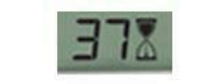
During the override, the bottom of the display shows the time (minutes) remaining in the override and an hourglass to indicate the override state.(See Figure 5).
Force to an Occupied State
- Press
and hold the button for 3 seconds to force the zone to an unoccupied state.
2.To cancel the force to unoccupied and return control to the schedule, press the
button again.
To Lock the Sensor Buttons of a ZS Push/Manager
Simultaneously press and hold the 2 buttons shown below (see Figure 6) for 5 seconds to lock the sensor’s buttons. The display shows a lock icon to indicate the
locked state.
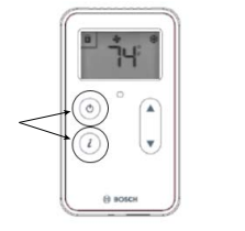
Press and hold the 2 buttons again for 5 seconds to unlock the buttons.
If you press the
button slightly before the

button, the sensor will go into an override state instead of locking the buttons. But, if you press the

button first, the buttons will lock.
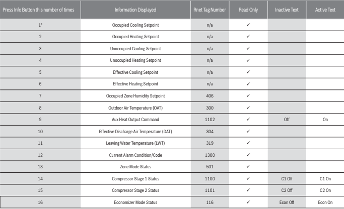
To Edit Displayed Values Using a ZS Push/Manager
If the display shows a value other than a zone temperature setpoint with

to the right of it, the value is editable from the sensor. An example is the screen for the zone humidity setpoint. Access this screen by pressing the info button several times (approx 7 times) until the humidity setpoint is visible (Rnet tag 406), then follow the steps below to change the value as needed (max of 95%rh, min of 20%rh):
Press the

or

button to adjust the value.
- Wait until the display returns to the home screen before you press any other buttons.
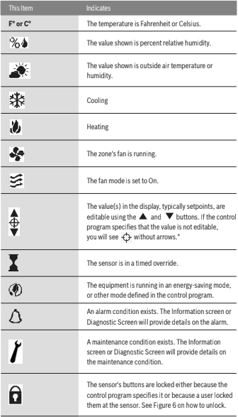
If the control program specifies that the value is not editable, you will see

without arrows.
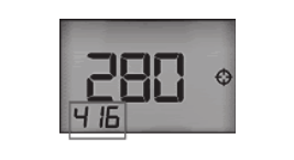
Rnet Tags
Rnet tags are numbers that identify types of system values, and determine how the ZS Series sensor will display those values. For example:
The Rnet tag number 416 indicates Air Flow Setpoint. Values such as this that do not have an icon will display the Rnet tag number in the lower left corner of the sensor’s display.(see Figure 7)
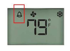
If there’s an active alarm(s) condition, pressing the info button once will first display the alarm page(s) including the corresponding Rnet tag and a short text, before resuming the regular cycle of functions.
Alarm conditions are indicated by the bell symbol appearing on the Pro sensor display (see figure 8).
The following is a description of the available alarm codes on the “Current Alarm Condition/Code” screen(Rnet tag 1300):
| Alarm Code | Description |
| 0 | System Normal – No Alarms |
| 1 | UPM code for High Pressure on circuit #1 fault |
| 2 | UPM code for Low Pressure on circuit #1 fault |
| 3 | UPM code for High Pressure on circuit #2 fault |
| 4 | UPM code for Low Pressure on circuit #2 fault |
| 5 | UPM code for Water Coil Freeze on circuit #1 fault |
| 6 | UPM code for High Condensate fault |
| 7 | UPM code for Brownout fault |
| 8 | UPM code for Air Coil Freeze on circuit #1 fault |
| 9 | UPM code for Water Coil Freeze on circuit #2 fault |
| 10 | UPM code for Air Coil Freeze on circuit #2 fault |
| 20 | FHP560 Input/Output in MANUAL lock position |
| 30 | Wired Sensor Failure for ZS Sensor, DAT Sensor, LWT Sensor, Humidity Sensor or CO2 Sensor |
| 40 | High or Low Leaving Water Temperature (LWT) Condition |
| 50 | High or Low Zone Temperature Condition |
| 60 | High or Low Discharge Air Temperature (DAT) Condition |
| 70 | Filter or Compressor Runtime Alert |
| 80 | High or Low Zone Humidity Condition |
| 90 | High Zone CO2 Condition |
| 100 | Differential Pressure Switch (DPS) Open Condition |
If an alarm is generated for any of the below conditions, pressing the info button will show a Alarm Code Description short “active text” and Rnet tag:
| Alarm Display Information | Rnet Tag Number | Active Text |
| Filter Change Status | 1027 | FILTER |
| Low Zone Temp Alarm | 1026 | Lo ZTp |
| High Zone CO2 Alarm | 1043 | HI CO2 |
| High Zone Humidity Alarm | 1044 | HI RH |
| Low Zone Humidity Alarm | 1045 | Lo RH |
| Compressor1 Runtime Alarm | 1050 | C1 RT |
| Compressor2 Runtime Alarm | 1051 | C2 RT |
| High Discharge Air Temp Alarm | 1028 | Hi DAT |
| Low Discharge Air Temp Alarm | 1029 | Lo DAT |
| Manual I/O Lock Alarm | 1116 | IO OVRD |
| Wired Sensor Failure Alarm | 1115 | SEN Conn |
| High Leaving Water Temp Alarm | 1113 | Load H2O |
| Low Leaving Water Temp Alarm | 1114 | Load H2O |
| High Zone Temp Alarm | 1025 | Hi ZTp |
| DPS Lock Alarm | 1117 | dPS |
| UPM General High Pressure Alarm | 1118 | HP Fault |
| UPM General Low Pressure Alarm | 1119 | LP Fault |
| UPM General Freezestat Alarm | 1120 | Frz stat |
| UPM Brownout BRN Alarm | 1109 | Brn Out |
| UPM Condensate COND Alarm | 1108 | Hi Cond |
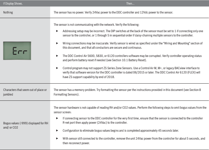
Troubleshooting
The following technical issues may be resolved as described below:
Battery Reset
If the software becomes corrupted the controller may be reset to the last saved/ archived version by performing the following:
- Remove the 24Vac power from the controller.
- Pull the 3V CR2032 onboard battery from the controller.
- Replace the onboard battery after approx 10 seconds.
- Reconnect the unit 24Vac power.
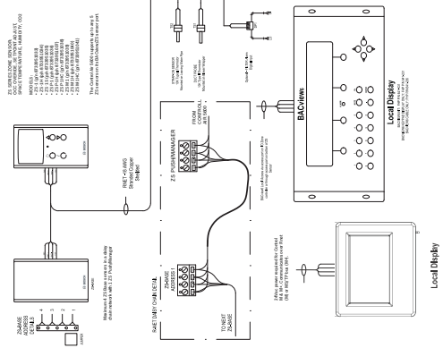
Wiring and Mounting
The Rnet cable is wired to the controller at the Rnet connector. The shield wire (if available) and the ground wire should be inserted into the controller’s GND
terminal.
- Turn off the controller’s power.
- Pull the back plate off the ZS Sensor. You may need to turn the setscrews in the bottom of the sensor clockwise until you can remove the back plate.
- Pull the Rnet communication cable through the slit in the insulated backing material.(See Figure 9)
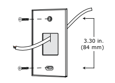
- Use 2 screws to mount the back plate to the wall or outlet box.
- Partially cut, then bend and pull off the outer jacket of the Rnet cable(s). Do not nick the inner insulation.(See Figure 10)
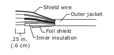
- 6. Strip about.25 inch (.6 cm) of the inner insulation from each wire.
- If wiring 1 cable to the ZS Sensor, cut the shield wire off at the outer jacket, then wrap the cable with tape at the outer jacket to cover the end of the
shield wire. - Insert the other 4 wires into the ZS Sensor’s screw terminal connector. If wiring 2 cables, insert like colored wires into each terminal.
| Connect this Wire | To this Terminal |
| RED | +12v |
| GREEN | Rnet- |
| WHITE | Rnet+ |
| BLACK | Gnd |
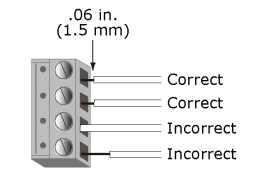
CAUTION: Allow no more than .06 inch (1.5mm) of bare communication wire contacts to avoid touching the cable’s foil shield wire, or a metal surface other than the terminal block. The device may not communicate correctly otherwise. (See Figure 11)
- Attach the sensor’s cover and circuit board to the mounted back plate, inserting the top first.
- Turn the setscrews one full turn counterclockwise so that the cover can not be removed.
Use the same polarity throughout the Rnet.
ZS Series Zone Sensor R1 Dimensions
Compatible Controllers
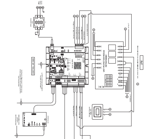
Electrical Schematic
Terminology
PSC – Permanent-split capacitor motor
EER – Energy Effi ciency Ratio
COP – Coeffi cient of Performance. The COP provides a measure of performance for
heat pumps that is analogous to thermal effi ciency for power cycles.
ECM – Electronically Commutated Motor.
UPM – Unit Protection Module
WLHP – Water Loop Heat Pump
GLHP – Ground Loop Heat Pump
RLA – Running Load Amps
LRA – Locked Rotor Amps
FLA – Full Load Amps
NPA – Name Plate Amps
HP – Heat Pump
Suction Pressure – Pressure entering compressor Discharge Pressure – Pressure leaving compressor (R/A) – Return Air
Recovery – Means the collection and storage of fluorinated greenhouse gases from products, including containers, and equipment during maintenance or
servicing or prior to the disposal of the products or equipment;
Recycling – Means the reuse of a recovered fluorinated greenhouse gas following a basic cleaning process;
Reclamation – Means the reprocessing of a recovered fluorinated greenhouse gas in order to match the equivalent performance of a virgin substance,
taking into account its intended use;
Decommissioning – Means the final shut-down and removal from operation or usage of a product or piece of equipment containing fluorinated greenhouse gases;
Repair – Means the restoration of damaged or leaking products or equipment that contain, or whose functioning relies upon, fluorinated greenhouse gases,
involving a part containing or designed to contain such gases;
Conditioned space – Space within a building provided with heated or cooled air, or both (or surfaces); and, where required, with humidification
or dehumidification means, to maintain conditions for an acceptable thermal environment.
Common Abbreviations
Abbreviation Description
AFMS Air Flow Measuring Station
AC Air Conditioning
ACU Air Conditioning Unit
AHU Air Handling Unit
AI Analog Input
AO Analog Output
AUTO Automatic
AUX Auxiliary
BAS Building Automation System
C Common (24Vac)
CHW Chilled Water
COND Condenser
COMP Compressor
CW Condenser Water
CWP Circulating Water Pump
DA Discharge Air
DDC Direct Digital Control
DES Damper End Switch
DFS Dirty Filter Switch
DI Digital Input
DO Digital Output
DPS Diff erential Pressure Switch
DX Direct Expansion
EA Exhaust Air
EF Exhaust Fan
EVAP Evaporator
EW Entering Water
F Fahrenheit
FM Flow Meter
FSS Fan Status Switch
HGRH Hot Gas Re-Heat
HP Heat Pump
HW Hot Water
IEM Input Expansion Module
LP Loop Pump
Table 17
Abbreviation Description
LW Leaving Water
MA Mixed Air
MAX Maximum
MIN Minimum
MINS Minutes
MISC Miscellaneous
MOD Modulating
NC Normally Closed
NO Normally Open
OA Outdoor Air
OAD Outdoor Air Damper
OCC Occupancy
R Hot (24Vac)
RA Return Air
RF Return Fan
RH Relative Humidity
RV Reversing Valve
SA Supply Air
SCR Silicon Controlled Rectifi er
SDP Secondary Drain Pan
SDS Smoke Detector Switch
SECS Seconds
SF Supply Fan
SOO Sequence of Operation
SP Static Pressure
S/S Start/Stop
STG Stage
TEMP Temperature
UI Universal Input
UPM Unit Protection Module
VAV Variable Air Volume
VES Valve End Switch
VFD Variable Frequency Drive
VLV Valve
WSE Water Side Economizer
WSHP Water Source Heat Pump
Table 18
Control Signals
| Signal | Description |
| G | Fan Signal |
| O | Reversing Valve Signal |
| Y1 | Compressor Stage 1 Signal |
| Y2 | Compressor Stage 2 Signal |
| W | Electric Heat Signal |
| H | Reheat Signal |
| EV | Economizer Valve Signal |
| CV | Condenser Valve Signal |
| P | Pump Signal |
You can download the PDF version of the Bosch ZS Series Zone Sensors R1 User’s Manual here.