
Thank you for purchasing this quality-built Troy-Bilt generator. We are pleased that you’ve placed your confidence in the Troy-Bilt brand. When operated and maintained according to the instructions in this manual, your Troy-Bilt generator will provide many years of dependable service.
This manual contains safety information to make you aware of the hazards and risks associated with generators and how to avoid them. This generator is designed and intended only for supplying electrical power for operating compatible electrical lighting, appliances, tools and motor loads, and is not intended for any other purpose. It is important that you read and understand these instructions thoroughly before attempting to start or operate this equipment. Save these original instructions for future reference.
This generator requires final assembly before use. Refer to the Assembly section of this manual for instructions on final assembly procedures. Follow the instructions completely.
Operator Safety
Equipment Description
Read this manual carefully and become familiar with your generator. Know its applications, its limitations and any hazards involved.
The generator is an engine–driven, revolving field, alternating current (AC) generator. It was designed to supply electrical power for operating compatible electrical lighting, appliances, tools and motor loads. The generator’s revolving field is driven at about 3,600 rpm by a single-cylinder engine.
NOTICE: Exceeding generators wattage/amperage capacity could damage generator and/or electrical devices connected to it.
• DO NOT exceed the generator’s wattage/amperage capacity. See Don’t Overload Generator in the Operation section.
Every effort has been made to ensure that the information in this manual is both accurate and current. However, the manufacturer reserves the right to change, alter or otherwise improve the generator and this documentation at any time without prior notice.
The Emission Control System for this generator is warranted for standards set by the Environmental Protection Agency and the California Air Resources Board.
Important Safety Information
The manufacturer cannot possibly anticipate every possible circumstance that might involve a hazard. The warnings in this manual, and the tags and decals affixed to the unit are, therefore, not all-inclusive. If you use a procedure, work method or operating technique that the manufacturer does not specifically recommend, you must satisfy yourself that it is safe for you and others. You must also make sure that the procedure, work method or operating technique that you choose does not render the generator unsafe.
Safety Symbols and Meanings


The safety alert symbol indicates a potential personal injury hazard. A signal word (DANGER, WARNING, or CAUTION) is used with the alert symbol to designate a degree or level of hazard seriousness. A safety symbol may be used to represent the type of hazard. The signal word NOTICE is used to address practices not related to personal injury.
DANGER indicates a hazard which, if not avoided, will result in death or serious injury.
WARNING indicates a hazard which, if not avoided, could result in death or serious injury.
CAUTION indicates a hazard which, if not avoided, could result in minor or moderate injury.
NOTICE address practices not related to personal injury.
Danger
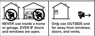
Using a generator indoors CAN KILL YOU IN MINUTES. Generator exhaust contains carbon monoxide. This is a poison you can not see or smell.
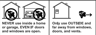
WARNING POISONOUS GAS HAZARD. Engine exhaust contains carbon monoxide, a poisonous gas that could kill you in minutes. You CANNOT smell it, see it, or taste it. Even if you do not smell exhaust fumes, you could still be exposed to carbon monoxide gas.
• Operate this product ONLY outside far away from windows, doors and vents to reduce the risk of carbon monoxide gas from accumulating and potentially being drawn towards occupied spaces.
• Install battery-operated carbon monoxide alarms or plug-in carbon monoxide alarms with battery back-up according to the manufacturer’s instructions. Smoke alarms cannot detect carbon monoxide gas.
• DO NOT run this product inside homes, garages, basements, crawlspaces, sheds, or other partially-enclosed spaces even if using fans or opening doors and windows for ventilation. Carbon monoxide can quickly build up in these spaces and can linger for hours, even after this product has shut off.
• ALWAYS place this product downwind and point the engine exhaust away from occupied spaces.
If you start to feel sick, dizzy, or weak while using this product, shut it off and get to fresh air RIGHT AWAY. See a doctor. You may have carbon monoxide poisoning.
WARNING: The engine exhaust from this product contains chemicals known to the State of California to cause cancer, birth defects, or other reproductive harm.
WARNING: Certain components in this product and related accessories contain chemicals known to the State of California to cause cancer, birth defects or other
reproductive harm. Wash hands after handling.
WARNING Starter cord kickback (rapid retraction) will pull hand and arm toward engine faster than you can let go which could cause broken bones, fractures, bruises, or sprains resulting in serious injury.
• When starting engine, pull cord slowly until resistance is felt and then pull rapidly to avoid kickback.
• NEVER start or stop engine with electrical devices plugged in and turned on.
WARNING Fuel and its vapors are extremely flammable and explosive which could cause burns, fire or explosion resulting in death or serious injury.
WHEN ADDING OR DRAINING FUEL
• Turn generator engine OFF and let it cool at least 2 minutes before removing fuel cap. Loosen cap slowly to relieve pressure in tank.
• Fill or drain fuel tank outdoors.
• DO NOT overfill tank. Allow space for fuel expansion.
• If fuel spills, wait until it evaporates before starting engine.
• Keep fuel away from sparks, open flames, pilot lights, heat, and other ignition sources.
• Check fuel lines, tank, cap and fittings frequently for cracks or leaks. Replace if necessary.
• DO NOT light a cigarette or smoke.
WHEN STARTING EQUIPMENT
• Ensure spark plug, muffler, fuel cap, and air cleaner are in place.
• DO NOT crank engine with spark plug removed.
WHEN OPERATING EQUIPMENT
• DO NOT operate this product inside any building, carport, porch, mobile equipment, marine applications, or enclosure.
• DO NOT tip engine or equipment at angle which causes fuel to spill.
• DO NOT stop engine by moving choke control to “Choke” position ( ).
WHEN TRANSPORTING, MOVING OR REPAIRING EQUIPMENT
• Transport/move/repair with fuel tank EMPTY or with fuel shutoff valve OFF.
• DO NOT tip engine or equipment at angle which causes fuel to spill.
• Disconnect spark plug wire.
WHEN STORING FUEL OR EQUIPMENT WITH FUEL IN TANK
• Store away from furnaces, stoves, water heaters, clothes dryers, or other appliances that have pilot light or other ignition source because they could ignite fuel vapors.
WARNING
• This generator does not meet U. S. Coast Guard Regulation 33CFR-183 and should not be used on marine applications.
• Failure to use the appropriate U. S. Coast Guard approved generator could result in death or serious injury and/or property damage.
WARNING Generator voltage could cause electrical shock or burn resulting in death or serious injury.
• Use approved transfer equipment to prevent back feed by isolating generator from electric utility workers.
• When using generator for backup power, notify utility company.
• Use a ground fault circuit interrupter (GFCI) in any damp or highly conductive area, such as metal decking or steel work.
• DO NOT touch bare wires or receptacles.
• DO NOT use generator with electrical cords which are worn, frayed, bare or otherwise damaged.
• DO NOT operate generator in the rain or wet weather.
• DO NOT handle generator or electrical cords while standing in water, while barefoot, or while hands or feet are wet.
• DO NOT allow unqualified persons or children to operate or service generator.
WARNING Exhaust heat/gases could ignite combustibles, structures or damage fuel tank causing a fire, resulting in death or serious injury. Contact with muffler area could cause burns resulting in serious injury.
• DO NOT touch hot parts and AVOID hot exhaust gases.
• Allow equipment to cool before touching.
• Keep at least 5 feet (1.5 m) of clearance on all sides of generator including overhead.
• It is a violation of California Public Resource Code, Section 4442, to use or operate the engine on any forest-covered, brush-covered, or grass-covered land unless the exhaust system is equipped with a spark arrester, as defined in Section 4442, maintained in effective working order. Other states or federal jurisdictions may have similar laws. Contact the original equipment manufacturer, retailer, or dealer to obtain a spark arrester designed for the exhaust system
installed on this engine.
• Replacement parts must be the same and installed in the same position as the original parts.
WARNING Unintentional sparking could cause fire or electric shock resulting in death or serious injury.
WHEN ADJUSTING OR MAKING REPAIRS TO YOUR GENERATOR
• Disconnect the spark plug wire from the spark plug and place the wire where it cannot contact spark plug.
WHEN TESTING FOR ENGINE SPARK
• Use approved spark plug tester.
• DO NOT check for spark with spark plug removed.
WARNING Starter and other rotating parts could entangle hands, hair, clothing, or accessories resulting in serious injury.
• NEVER operate generator without protective housing or covers.
• DO NOT wear loose clothing, jewelry or anything that could be caught in the starter or other rotating parts.
• Tie up long hair and remove jewelry.
CAUTION Excessively high operating speeds could result in minor injury.
Excessively low speeds impose a heavy load.
• DO NOT tamper with governor spring, links or other parts to increase engine speed. Generator supplies correct rated frequency and voltage when running at governed speed.
• DO NOT modify generator in any way.
NOTICE Exceeding generators wattage/amperage capacity could damage generator and/or electrical devices connected to it.
• DO NOT exceed the generator’s wattage/amperage capacity. See Don’t Overload Generator in the Operation section.
• Start generator and let engine stabilize before connecting electrical loads.
• Connect electrical loads in OFF position, then turn ON for operation.
• Turn electrical loads OFF and disconnect from generator before stopping generator.
NOTICE Improper treatment of generator could damage it and shorten its life.
• Use generator only for intended uses.
• If you have questions about intended use, ask dealer or contact local service center.
• Operate generator only on level surfaces.
• DO NOT expose generator to excessive moisture, dust, dirt, or corrosive vapors.
• DO NOT insert any objects through cooling slots.
• If connected devices overheat, turn them off and disconnect them from generator.
• Shut off generator if:
-electrical output is lost;
-equipment sparks, smokes, or emits flames;
-unit vibrates excessively.
Assembly
Read entire operator’s manual before you attempt to assemble or operate your new generator.
Your generator requires some assembly and is ready for use after it has been properly serviced with the recommended fuel and oil level is verified.
If you have any problems with the assembly of your generator, please call the generator helpline at (888) 611-6708. If calling for assistance, please have the model, revision, and serial number from the identification label available. See generator Features and Controls for identification label location.
Unpack Generator
- Set the carton on a rigid, flat surface.
- Remove everything from carton except generator.
- Open carton completely by cutting each corner from top to bottom.
- Leave generator on carton to install wheel kit.
The generator is supplied with:
• Operator’s manual
• Engine oil bottle
• Battery float charger
• Extend-a-panel TM
• 25 ft. (7.6 m) Accessory cord
• Wheel kit
Install Wheel Kit
NOTICE Wheel kit is not intended for over-the-road use. You will need the following tools to install these components:
• 13 mm wrenches (2)
• Adjustable wrench
• Pliers
• Safety glasses
Install the wheel kit as follows:
- Tip generator so that engine side is down. Tip generator back slightly and slide narrow end of one of the support legs under engine recoil.
NOTICE Be sure to slide support leg far enough under engine recoil to prevent generator from tipping over.
2.Slide axle (A) through holes in generator frame.
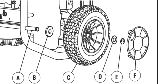
- Slide a black nylon washer (B) over axle.
- Slide a wheel (C) over axle.
CAUTION E-rings could cause eye injury. E-rings could spring back and become airborne when installing or removing, resulting in moderate injury.
• Always wear eye protection when installing/removing e-rings.
- Install e-ring with pliers, squeezing from top of e-ring to bottom of axle.
- Place hub cap (F) into center of wheel and push until it snaps into place.
- Repeat step 3 thru 8 to secure second wheel.
- Tip generator back slightly and remove support leg from under engine recoil.
- Line up holes in support leg (G) with holes in generator frame.
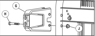
- Attach support leg using two cap screws (H) and two hex nuts (J). Tighten with 13 mm wrenches.
- Repeat step 11 and 12 to secure second support leg.
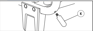
- Attach cord wrap posts (K) to generator frame. Tighten with an adjustable wrench.
- Return generator to normal operating position (resting on wheels and support legs).
Moving Generator
- Remove handle pin (A) from bracket on right side of handle (viewing generator from engine end).
- Pull folding handle to the upright position until latch (B) locks into place.
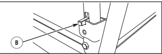
3.Reinsert handle pin in bracket on right side of handle.
WARNING Body Crush/Tip Over Hazard. Generator could tip over while moving resulting in serious injury.
• Handle pin must be installed prior to moving generator.
- Place your foot onto the axle (C) located under the recoil starter and pull back on the handle.
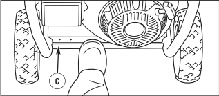
- Always face generator and push or pull to desired location. When moving generator on an incline, always make sure you are uphill from generator.
- Place foot on axle and gently let generator tip forward to rest on support leg.
- Remove handle pin from right side of handle.
- Pull up on latch and push handle forward to fold down handle.
Add Engine Oil
- Place generator on a flat, level surface.
- Clean area around oil fill and remove yellow oil fill cap/dipstick.
- Using oil funnel (optional), slowly pour contents of provided oil bottle into oil fill opening to the “Full” mark on dipstick.
NOTICE Improper treatment of generator could damage it and shorten its life.
• DO NOT attempt to crank or start the engine before it has been properly serviced with the recommended oil. This may result in an engine failure.
4.Replace oil fill cap/dipstick and fully tighten.
Add Fuel
Fuel must meet these requirements:
• Clean, fresh, unleaded gasoline.
• A minimum of 87 octane/87 AKI (91 RON). For high altitude use, see High Altitude.
• Gasoline with up to 10% ethanol (gasohol) is acceptable.
NOTICE Use of unapproved fuels could damage generator and voids warranty.
• DO NOT use unapproved gasoline such as E15 and E85.
• DO NOT mix oil in gasoline or modify engine to run on alternate fuels.
To protect the fuel system from gum formation, mix in a fuel stabilizer when adding fuel. See Storage. All fuel is not the same. If you experience starting or performance problems after using fuel, switch to a different fuel provider or change brands. This engine is certified to operate on gasoline. The emission
control system for this engine is EM (Engine Modifications).
WARNING Fuel and its vapors are extremely flammable and explosive which could cause burns, fire or explosion resulting in death or serious injury.
WHEN ADDING FUEL
• Turn generator engine OFF and let it cool at least 2 minutes before removing fuel cap. Loosen cap slowly to relieve pressure in tank.
• Fill fuel tank outdoors.
• DO NOT overfill tank. Allow space for fuel expansion.
• If fuel spills, wait until it evaporates before starting engine.
• Keep fuel away from sparks, open flames, pilot lights, heat, and other ignition sources.
• Check fuel lines, tank, cap and fittings frequently for cracks or leaks. Replace if necessary.
• DO NOT light a cigarette or smoke.
- Clean area around fuel fill cap, remove cap.
- Slowly add unleaded gasoline (D) to fuel tank (E). Be careful not to fill above the baffle (F). This allows adequate space for fuel expansion as shown.
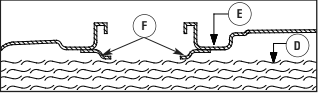
- Install fuel cap and let any spilled fuel evaporate before starting engine.
High Altitude
At altitudes over 5,000 feet (1524 meters), a minimum 85 octane / 85 AKI (89 RON) gasoline is acceptable. To remain emissions compliant, high altitude adjustment is required. Operation without this adjustment will cause decreased performance, increased fuel consumption, and increased emissions. See an authorized dealer for high altitude adjustment information. Operation of the engine at altitudes below 2,500 feet (762 meters) with the high altitude kit is not recommended.
Attach Negative Battery Cable
Your unit is equipped with electric start capability but can be started manually. If you choose not to use the electric start feature, you do not need to connect the negative battery cable.
The sealed battery on the generator pre–installed except for the negative (black) battery cable.
WARNING Battery posts, terminals and related accessories contain lead and lead compounds – chemicals known to the State of California to cause cancer and
reproductive harm. Wash hands after handling.
To install:
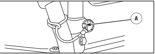
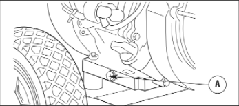
- Cut off tie wrap securing loose end of negative (black) cable.
- Using an 8 mm or 5/16” socket wrench, remove screw (A), lock washer (B) and flat washer (C) on negative battery terminal.
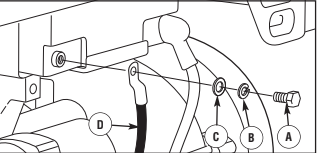
- Slide lock washer, flat washer and negative battery cable (D) over screw as shown.
- Reattach screw to negative battery terminal and tighten.
- Verify that connections to battery and generator are tight and secure.
NOTICE If your battery is discharged, charge prior to use following the instructions in the section Battery Charger.
Attach Extend-a-panel TM
The Extend-a-panel TM can be connected to the generator directly or with the provided 20 Amp, 25 ft. (7.6 m) accessory cord. To connect the Extend-a-panel TM directly to the generator, follow these instructions:
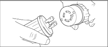
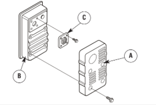
1.Twist knob (E) on main panel to horizontal position.
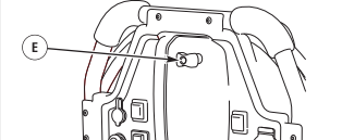
- Place hole at top of Extend-a-panelTM over knob on main panel.
- Twist knob to vertical position to lock Extend-a-panelTM onto main panel.

- Connect Extend-a-panel TM twist lock to small twist lock cord under main panel on generator.
- Connect Extend-a-panel TM two-pin connector to small two-pin connector cord under main panel on generator.
System Ground
The generator has a system ground that connects the generator frame components to the ground terminals on the AC output receptacles. The system ground is connected to the AC neutral wire (the neutral is bonded to the generator frame).
Special Requirements
There may be Federal or State Occupational Safety and Health Administration (OSHA) regulations, local codes, or ordinances that apply to the intended use of the generator. Please consult a qualified electrician, electrical inspector, or the local agency having jurisdiction:
• In some areas, generators are required to be registered with local utility companies.
• If the generator is used at a construction site, there may be additional regulations which must be observed.
Connecting to a Building’s Electrical System
Connections for standby power to a building’s electrical system must be made by a qualified electrician. The connection must isolate the generator power from utility power and must comply with all applicable laws and electrical codes.
WARNING Generator voltage could cause electrical shock or burn resulting in death or serious injury.
• Use approved transfer equipment to prevent back feed by isolating generator from electric utility workers.
• When using generator for backup power, notify utility company.
• Use a ground fault circuit interrupter (GFCI) in any damp or highly conductive area, such as metal decking or steel work.
• DO NOT touch bare wires or receptacles.
• DO NOT use generator with electrical cords which are worn, frayed, bare or otherwise damaged.
• DO NOT operate generator in the rain or wet weather.
• DO NOT handle generator or electrical cords while standing in water, while barefoot, or while hands or feet are wet.
• DO NOT allow unqualified persons or children to operate or service generator.
Generator Location
Carbon Monoxide Poisoning
Danger
Using a generator indoors CAN KILL YOU IN MINUTES. Generator exhaust contains carbon monoxide. This is a poison you can not see or smell.
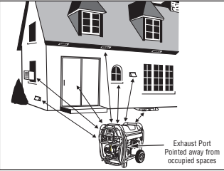
Operate this product ONLY outside far away from windows, doors and vents to reduce the risk of carbon monoxide gas from accumulating and potentially being drawn towards occupied spaces. Install/maintain battery-operated carbon monoxide alarms or plug-in carbon monoxide alarms with battery back-up according to the manufacturer’s instructions. DO NOT run this product inside homes, garages, basements, crawlspaces, sheds, or other partially-enclosed spaces even if
using fans or opening doors and windows for ventilation. ALWAYS place this product downwind and point the engine exhaust away from occupied spaces.
Risk of Fire Clearances
WARNING Exhaust heat/gases could ignite combustibles, structures or damage fuel tank causing a fire, resulting in death or serious injury.
• Keep at least 5 ft. (1.5 m) clearance on all sides of generator including overhead.
Features and Controls
Generator
Read this Operator’s Manual and safety rules before operating your generator.
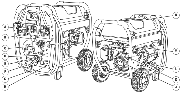
A – Main Control Panel — Permanently affixed to generator.
B – Extend-a-panel TM — May be removed and connected to generator with accessory cord for remote operation.
C – Spark Arrester Muffler — Exhaust muffler lowers engine noise and is equipped with a spark arrester screen.
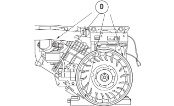
D – Twist lock Connector — Used to connect Extend-a panel TM directly to generator or with provided accessory cord.
E – 2 Pin Connector — Plug in to sense current for dual load monitoring on Extend-a-panel TM.
F – Grounding Fastener — Consult your local agency having jurisdiction for grounding requirements in your area.
G – Accessory Cord — Extend-a-panel TM can be connected to generator with provided 20 Amp, 25 ft. (7.6 m) accessory cord.
H – Identification Label — Provides model, revision and serial number of generator. Please have these readily available when calling for assistance.
J – Air Cleaner — Protects engine by filtering dust and debris out of intake air.
K – Recoil Starter — Used to start the engine manually.
L – Oil Fill Cap — Check and add engine oil here.
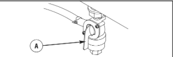
M – Fuel Valve — Used to turn fuel supply on and off to engine.
N – Fuel Tank — Capacity of 8.5 U.S. gallons (32.2 l). Items Not Shown:
Engine Identification — Provides model, type and code of engine. Please have these readily available if calling for assistance.
Oil Drain Plug — Drain engine oil here.
Control Panel
Read this Operator’s Manual and safety rules before operating your generator.
Compare the illustrations with your control panel, to familiarize yourself with the locations of various controls and adjustments. Save this manual for future reference.
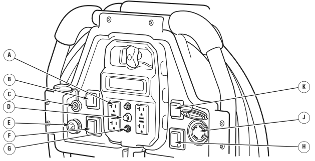
A – 120 Volt AC, 20 Amp, GFCI Duplex Receptacles — May be used to supply electrical power for the operation of 120 Volt AC, 20 Amp, single phase, 60 Hz electrical, lighting, appliance, tool and motor loads.
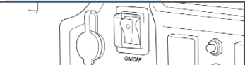
B – On/Off Switch — Set this switch to on (I) before starting engine. Set switch to off (O) to shut off engine.
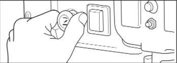
C – Battery Float Charger Jack — Use battery float charger jack to keep the starting battery charged and ready for use.
D – Display Button — Push to scroll through LCD screens on Extend-a-panel TM. Also push and hold for a minimum of 3 seconds to reset maintenance reminders and security features.
E – Choke Control — Used when starting a cold engine.
F – Start Switch — Push and hold in “Start” position for a maximum of 5 seconds during each start attempt, until engine starts.
G – Circuit Breakers (AC) — The 120 Volt AC, 20A GFCI duplex receptacles are provided with “push to reset” circuit breakers to protect the generator against electrical overload.
H – Rocker Switch Main Circuit Breaker — The 120/240 Volt AC, 30A locking receptacle is provided with a rocker switch circuit breaker to protect generator
against electrical overload.
J – 120/240 Volt AC, 30 Amp Locking Receptacle — May be used to supply electrical power for the operation of 120 and/or 240 Volt AC, 30 Amp, single phase, 60 Hz electrical, lighting, appliance, tool and motor loads.
K – Rocker Switch Cord set Circuit Breaker — The cord set on main panel is provided with a double pole rocker switch circuit breaker to protect generator against
electrical overload.
Battery Charger
Use battery float charger jack to keep the starting battery charged and ready for use. Battery charging should be done in a dry location, such as inside a garage.
- Plug charger into unit’s “Battery Float Charger” jack, which is located above on/off switch. Plug battery charger into a 120 Volt AC wall receptacle.
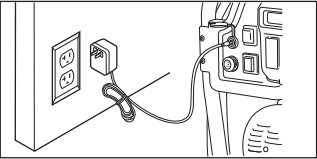
- Unplug charger from unit and wall outlet when generator is being started and while it is in operation.
- Keep this charger plugged in when generator is not in use to prolong battery life. The charger has a built in float equalizer and will not overcharge the battery, even when plugged in for an extended period of time.
NOTICE See Battery Maintenance for additional information.
Cord Sets and Receptacles
Use only high quality, well-insulated, grounded extension cords with the generator’s receptacles. Inspect extension cords before each use.
Check the ratings of all extension cords before you use them. Check the operator’s manuals of devices for the manufacturer’s recommendations.
WARNING Damaged or overloaded electrical cords could overheat, arc, and burn resulting in death or serious injury.
• ONLY use cords rated for your loads.
• Follow all safeties on electrical cords.
• Inspect cord sets before each use.
A double pole rocker switch circuit breaker is provided to protect the locking receptacle. If this circuit breaker is tripped, all receptacles are disconnected.
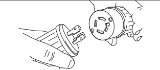
120/240 Volt AC, 30 Amp, Locking Receptacle
Use a NEMA L14-30 plug with this receptacle. Connect a 4-wire cord set rated for 250 Volt AC loads at 30 Amps (or greater). You can use the same 4-wire cord if you plan to run a 120 Volt load.
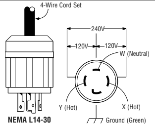
This receptacle powers 120/240 Volt AC, 60 Hz, single phase loads requiring up to 7,000 watts of power (7.0 kW) at 29.1 Amps for 240 Volts or two independent 120 Volt loads at 29.1 Amps each. The outlet is protected by a two pole rocker switch circuit breaker.
NOTICE Receptacles may be marked with rating value greater than generator output capacity.
• NEVER attempt to power a device requiring more amperage than generator or receptacle can supply.
• DO NOT overload the generator. See Don’t Overload Generator.
Extend-a-panel TM
A double pole rocker switch circuit breaker on the main panel is provided to protect the cord set off main panel. If this circuit breaker is tripped, all power from cord set is disconnected.
120 Volt AC, 20 Amp, GFCI Duplex Receptacles
The Extend-a-panel TM has two 120 Volt, 20 Amp GFCI duplex receptacles. Each receptacle is protected against overload by push-to-reset circuit breakers.
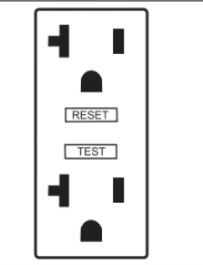
Use each receptacle to operate 120 Volt AC, single-phase, 60 Hz electrical loads requiring up to 2,400 watts (2.4 kW) at 20 Amps of current. Use cord sets that are rated for 125 Volt AC loads at 20 Amps (or greater). Inspect cord sets before each use.
Ground Fault Protection
The duplex receptacles are equipped with Ground Fault Circuit Interrupter (GFCI) protection. This device meets applicable federal, state and local codes. The generator’s locking receptacle is not protected by a Ground Fault Circuit Interrupter (GFCI).
The GFCI protects against electrical shock that may be caused if your body becomes a path which electricity travels to reach ground. This could happen if you touch a “Live” appliance or wire, or are touching plumbing or other materials that connect to the ground.
When protected by a GFCI, one may still feel a shock, but the GFCI should cut current off quickly enough so that a person in normal health should not suffer any serious electrical injury.
WARNING Generator voltage could cause electrical shock or burn resulting in death or serious injury.
• Contact with the hot and neutral conductor at the same time can cause electrical shock or burn, even if the circuit is GFCI protected.
• Before using the GFCI receptacle, ALWAYS push the test button to insure it works.
Testing the GFCI
Test your GFCI outlet prior to each use, as follows:
• Push the “Test” button. The “Reset” button should pop out, which should allow no power to reach the outlet. Use a test lamp in each outlet to test this.
• If the GFCI tests good, restore power by pressing the “Reset” button firmly until it is fully in place and locks in that position. If the GFCI outlet does not reset
properly, do not use the outlet. Call or take your generator to a local service center.
• If the GFCI trips by itself at any time, reset and test the outlet. If the reset button does not pop out when the test button is pressed, do not use the outlet. Call or
take your generator to a local service center.
Extend-a-panel TM Accessory Cord
The Extend-a-panel TM can be connected to the generator directly or with the provided 20 Amp, 25 ft. (7.6 m) accessory cord. When using the 25 ft. (7.6 m) accessory cord with the Extend-a-panel TM, always make sure to follow all safeties and instructions on cord.
- Disconnect Extend-a-panel TM twist lock from small twist lock cord under main panel on generator.
- Disconnect Extend-a-panel TM two-pin connector from small two-pin connector cord under main panel on generator.
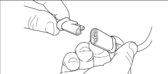
- Connect Extend-a-panel TM twist lock and two-pin connector to female end of accessory cord.
- Connect male end of accessory cord twist lock and two-pin connector to small cords under main panel on
NOTICE DO NOT exceed a seperation length of 50 ft. (15.24 m) or a combination of two Extend-a-panel TM accessory cords. Use only with original replacement
accessory cords.
Extend-a-panel TM LCD
The Extend-a-panel TM also has a built in LCD display with alarm system to monitor the following features:
• Dual Load Monitor (Panel and Total)
• Maintenance Reminder
• Security Warning
• Generator Shutdown
Dual Load Monitor
The dual load monitor measures the wattage output of the Extend-a-panel TM 120V, 20A receptacles and will display “PANEL” along with bars and percentage of load. Each duplex receptacle will operate 120 Volt AC, single-phase, 60 Hz electrical loads requiring up to 2,400 watts (2.4 kW) at 20 Amps of current for a total of 4,800 watts (4.8 kW).
The “TOTAL” displays the wattage output of all receptacles on the main panel and Extend-a-panel TM. The LCD will display “TOTAL” along with bars and percentage of load. If only the 120/240V, 30A receptacle is used, the LCD on the Extend-a- panel TM will display “TOTAL” only.

If the wattage output of either the “PANEL” or “TOTAL” is between 90% and 100%, the text will flash. If either reaches 101%, the LCD display will change to “OVERLOAD REMOVE LOAD”. An audible beep will sound until enough load is removed and the wattage output is below 101%.

• “AIR FILTER 25HRS HOLD TO RESET” after every 25 hours of operation.
• “CHANGE OIL 50HRS HOLD TO RESET” after every 50 hours of operation.
• “SPARK PLG 100HRS HOLD TO RESET” after every 100 hours of operation.
You must push and hold the display button on the Extend a panel TM for a minimum of 3 seconds to reset the timer after each maintenance interval.
Security Warning
The Extend-a-panel TM has a built in security warning that sounds an audible beep when the generator shuts down or if the Extend-a-panel TM is disconnected from the generator. The LCD will display “GENERATOR SHUTDOWN” and sound an audible beep for 5 seconds. The LCD backlight will turn off when the audible beep stops.

The security warning can be turned off if desired. To turn the audible beep from the security warning off, push the display button to scroll through the maintenance screens until the LCD displays “SECURITY WRNG ON HOLD TO SET”. Push and hold the display button until the LCD displays “SECURITY WRNG OFF HOLD TO SET”.

NOTICE By turning the security warning off, the audible beep will also be turned off if the panel or generator is overloaded.
Generator Shutdown
In order for the generator shutdown feature to work as described in Security Warning, you must install 4 AAA batteries (not supplied) into the back of the Extend-a-panel TM.

Operation
Starting the Engine
NOTICE Always unplug the battery float charger before starting the generator.
Disconnect all electrical loads from the generator. Use the following start instructions:
1.Make sure unit is on a level surface.
NOTICE Failure to start and operate the unit on a level surface will cause the unit not to start or shut down during operation.
2.Turn the fuel valve (A) to the “On” position.
3.Set on/off switch to on (I) position.
4.Pull choke handle out to choke ( ) position.
5A. For electric starting, push and hold the start switch in “Start” position until generator starts. To prolong the life of starter components, DO NOT hold start switch in “Start” position for more than 5 seconds, and pause for at least 1 minute between starting attempts.

• If engine starts, proceed to step 7.
• If engine fails to start, proceed to step 6.
NOTICE If battery is discharged, use manual starting instructions.
5B. For manual starting, grasp recoil handle and pull slowly until slight resistance is felt. Then pull rapidly one time only to start engine.
WARNING Starter cord kickback (rapid retraction) will pull hand and arm toward engine faster than you can let go which could cause broken bones, fractures, bruises, or sprains resulting in serious injury.
• When starting engine, pull cord slowly until resistance is felt
and then pull rapidly to avoid kickback.
• NEVER start or stop engine with electrical devices plugged in
and turned on.
• When starting engine, pull cord slowly until resistance is felt and then pull rapidly to avoid kickback.
• NEVER start or stop engine with electrical devices plugged in and turned on.
• If engine starts, proceed to step 7.
• If engine fails to start, proceed to step 6.
- Push in the choke handle half way, and pull recoil handle twice or push and hold the start switch in the “Start” position as described in step 5A.
• If engine fails to start, repeat steps 4 thru 5.
- As the engine warms up, gradually push choke handle in to run ( ) position.
NOTICE: If engine floods, push choke handle all the way in to run ( ) position, and crank until engine starts.
NOTICE: If engine starts after 3 pulls but fails to run, or if unit shuts down during operation, make sure unit is on a level surface and check for proper oil level in crankcase. This unit may be equipped with a low oil protection device. If so, oil must be at proper level for engine to start.
WARNING: Exhaust heat/gases could ignite combustibles, structures or damage fuel tank causing a fire, resulting in death or serious injury. Contact with muffler area could cause burns resulting in serious injury.
• DO NOT touch hot parts and AVOID hot exhaust gases.
• Allow equipment to cool before touching.
• Keep at least 5 feet (1.5 m) of clearance on all sides of generator including overhead.
• It is a violation of California Public Resource Code, Section 4442, to use or operate the engine on any forest-covered, brush-covered, or grass-covered land unless the exhaust system is equipped with a spark arrester, as defined in Section 4442, maintained in effective working order. Other states or federal jurisdictions may have similar laws. Contact the original equipment manufacturer, retailer, or dealer to obtain a spark arrester designed for the exhaust system
installed on this engine.
• Replacement parts must be the same and installed in the same position as the original parts.
Connecting Electrical Loads
- Let engine stabilize and warm up for a few minutes after starting.
- Ensure rocker switch circuit breakers on main panel are in “On” position.
- Plug in and turn on the desired 120 and/or 240 Volt AC, single phase, 60 Hz electrical loads.
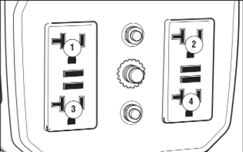
NOTICE: When plugging into the 120 Volt receptacles on Extend-a-panel TM, plug items to be powered in sequence as shown below.
NOTICE
• DO NOT connect 240 Volt loads to 120 Volt duplex receptacles.
• DO NOT connect 3-phase loads to generator.
• DO NOT connect 50 Hz loads to generator.
• DO NOT OVERLOAD THE GENERATOR. See Don’t Overload Generator.
NOTICE: Exceeding generators wattage/amperage capacity could damage generator and/or electrical devices connected to it.
• DO NOT exceed the generator’s wattage/amperage capacity. See Don’t Overload Generator in the Operation section.
• Start generator and let engine stabilize before connecting electrical loads.
• Connect electrical loads in OFF position, then turn ON for operation.
• Turn electrical loads OFF and disconnect from generator before stopping generator.
Stopping the Engine
- Turn OFF and unplug all electrical loads from generator panel receptacles. NEVER start or stop engine with electrical devices plugged in and turned ON.
- Let engine run at no-load for several minutes to stabilize internal temperatures of engine and generator.
- Push on/off switch to off (O) position.
WARNING: Fuel and its vapors are extremely flammable and explosive which could cause burns, fire or explosion resulting in death or serious injury.
• DO NOT stop engine by moving choke handle to “Choke” position ( ).
4.Move fuel valve to “Off” position.
Low Oil Shutdown
If the engine oil drops below a preset level, an oil switch will stop the engine. Check oil level with dipstick.
If oil level is between ADD and FULL mark on dipstick:
- DO NOT try to restart the engine.
- Contact an Authorized Briggs & Stratton Service Dealer.
- DO NOT operate engine until oil level is corrected.
If oil level is below ADD mark on dipstick:
- Add oil to bring level to FULL mark.
- Restart engine and if the engine stops again a low oil condition may still exist. DO NOT try to restart the engine.
- Contact an Authorized Briggs & Stratton Service Dealer.
- DO NOT operate engine until oil level is corrected.
Cold Weather Operation
Under certain weather conditions (temperatures below 40°F [4°C] combined with high humidity), your generator may experience icing of the carburetor and/or the crankcase breather system. To reduce this problem, you need to perform the following:
- Make sure generator has clean, fresh fuel.
- Open fuel valve (turn valve to open position).
- Use SAE 5W-30 oil.
- Check oil level daily or after every eight (8) hours of operation.
- Maintain generator following Maintenance Schedule in Maintenance section.
- Shelter unit from elements.
Creating a Temporary Cold Weather Shelter
- For temporary shelter, the original shipping carton can be used.
- Cut off top carton flaps and one long side of carton to expose muffler side of unit. If required, tape up other sides of carton to fit over generator as shown.
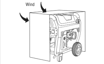
NOTICE If required, remove wheel kit to fit carton over generator as shown.
- Cut appropriate slots to access receptacles of unit.
- Face exposed end away from wind and elements.
- Locate generator as described in the section Generator Location. Keep exhaust gas from entering a confined area through windows, doors, ventilation intakes or other openings.
WARNING POISONOUS GAS HAZARD. Engine exhaust contains carbon monoxide, a poisonous gas that could kill you in minutes. You CANNOT smell it, see it, or taste it. Even if you do not smell exhaust fumes, you could still be exposed to carbon monoxide gas.
• Operate this product ONLY outside far away from windows, doors and vents to reduce the risk of carbon monoxide gas from accumulating and potentially being drawn towards occupied spaces.
• Install battery-operated carbon monoxide alarms or plug-in carbon monoxide alarms with battery back-up according to the manufacturer’s instructions. Smoke alarms cannot detect carbon monoxide gas.
• DO NOT run this product inside homes, garages, basements, crawlspaces, sheds, or other partially-enclosed spaces even if using fans or opening doors and windows for ventilation. Carbon monoxide can quickly build up in these spaces and can linger for hours, even after this product has shut off.
• ALWAYS place this product downwind and point the engine exhaust away from occupied spaces.
If you start to feel sick, dizzy, or weak while using this product, shut it off and get to fresh air RIGHT AWAY. See a doctor. You may have carbon monoxide poisoning.
- Start generator as described in the section Starting the Engine, then place carton over generator. Keep at least 5 ft. (1.5 m) clearance on all sides of generator including overhead with shelter in place.
WARNING: Exhaust heat/gases could ignite combustibles, structures or damage fuel tank causing a fire, resulting in death or serious injury. Contact with muffler area could cause burns resulting in serious injury.
• DO NOT touch hot parts and AVOID hot exhaust gases.
• Allow equipment to cool before touching.
• Keep at least 5 feet (1.5 m) of clearance on all sides of generator including overhead.
• Remove shelter when temperatures are above 40°F [4°C].
- Remove shelter when temperatures are above 40°F [4°C].
- Turn engine OFF and let cool two (2) minutes before refueling. Let any spilled fuel evaporate before starting engine.
Building a Cold Weather Shelter
- Using non combustible material with a fire rating of at least one hour, build a shelter that will enclose three sides and the top of the generator. Make sure muffler side of generator is exposed.
NOTICE: Contact your local building material supplier for non combustible materials with a fire rating of at least one hour.
NOTICE: Be sure shelter can easily be repositioned for change in wind direction.
- DO NOT enclose generator any more than shown. Shelter should hold enough heat created by the generator to prevent icing problem.
NOTICE: If a wheel kit is installed on the generator, enlarge shelter accordingly.
- Follow steps 3 through 8 as described previously in Creating a Temporary Cold Weather Shelter.
Don’t Overload Generator
Capacity
You must make sure your generator can supply enough rated (running) and surge (starting) watts for the items you will power at the same time. Follow these simple steps:
- Select the items you will power at the same time.
- Total the rated (running) watts of these items. This is the amount of power your generator must produce to keep your items running. See Wattage Reference Guide.
- Estimate how many surge (starting) watts you will need. Surge wattage is the short burst of power needed to start electric motor-driven tools or appliances such as a circular saw or refrigerator. Because not all motors start at the same time, total surge watts can be estimated by adding only the item(s) with the highest additional surge watts to the total rated watts from step 2.
Example:
| Tool or Appliance | Watts | (Starting) Watts |
| Window Air Conditioner | 1200 | 1800 |
| Refrigerator | 800 | 1600 |
| Deep Freezer | 500 | 500 |
| television | 500 | – |
| Light (75 Watts) | 75 | |
| 3075 Total Running Watts | 1800 Highest Surge Watts |
Total Rated (Running) Watts = 3075
Highest Additional Surge Watts = 1800
Total Generator Output Required = 4875
Power Management
To prolong the life of your generator and attached devices, it is important to take care when adding electrical loads to your generator. There should be nothing connected to the generator outlets before starting its engine. The correct and safe way to manage generator power is to sequentially add loads as follows:
- With nothing connected to the generator, start the engine as described in this manual.
- Plug in and turn on the first load, preferably the largest load you have.
- Permit the generator output to stabilize (engine runs smoothly and attached device operates properly).
- Plug in and turn on the next load.
- Again, permit the generator to stabilize.
- Repeat steps 4 and 5 for each additional load.
NEVER add more loads than the generator capacity. Take special care to consider surge loads in generator capacity, as described above.
| Tool or Appliance | Rated* (Running) Watts | Additional Surge (Starting) Watts |
| Essentials | ||
| Light Bulb – 75 watt | 75 | – |
| Deep Freezer | 500 | 500 |
| Sump Pump | 800 | 1200 |
| Refrigerator/Freezer – 18 Cu. Ft. | 800 | 1600 |
| Water Well Pump – 1/3 HP | 1000 | 2000 |
| Heating/Cooling | ||
| Window AC – 10,000 BTU | 1200 | 1800 |
| Window Fan | 300 | 600 |
| Furnace Fan Blower – 1/2 HP | 800 | 1300 |
| Kitchen | ||
| Microwave Oven – 1000 Watt | 1000 | – |
| Coffee Maker | 1500 | – |
| Electric Stove – Single Element | 1500 | – |
| Hot Plate | 2500 | – |
| Family Room | ||
| DVD/CD Player | 100 | – |
| VCR | 100 | – |
| Stereo Receiver | 450 | – |
| Color Television – 27” | 500 | – |
| Personal Computer w/17” monitor | 800 | – |
| Other | ||
| Security System | 180 | – |
| AM/FM Clock Radio | 300 | – |
| Garage Door Opener – 1/2 HP | 480 | 520 |
| Electric Water Heater – 40 Gallon | 4000 | – |
| DIY/Job Site | ||
| Quartz Halogen Work Light | 1000 | – |
| Airless Sprayer – 1/3 HP | 600 | 1200 |
| Reciprocating Saw | 960 | 960 |
| Electric Drill – 1/2 HP | 1000 | 1000 |
| Circular Saw – 7 1/4” | 1500 | 1500 |
| Miter Saw – 10” | 1800 | 1800 |
| Table Planer – 6” | 1800 | 1800 |
| Table Saw/Radial Arm Saw – 10” | 2000 | 2000 |
| Air Compressor – 1-1/2 HP | 2500 | 2500 |
- Wattages listed are approximate only. Check tool or appliance for actual wattage.
Maintenance
Maintenance Schedule
Follow the hourly or calendar intervals, whichever occurs first. More frequent service is required when operating in adverse conditions noted below.
| First 5 Hours |
| • Change engine oil |
| Every 8 Hours or Daily |
| • Clean debris |
| • Check engine oil level |
| Every 25 Hours or Yearly |
| • Clean engine air filter1 |
| Every 50 Hours or Yearly |
| • Change engine oil1 |
| Yearly |
| • Replace engine air filter1 |
| • Service fuel valve |
| • Service spark plug |
| • Inspect muffler and spark arrester |
General Recommendations
Regular maintenance will improve the performance and extend the life of the generator. See any authorized dealer for service.
The generator’s warranty does not cover items that have been subjected to operator abuse or negligence. To receive full value from the warranty, the operator must maintain the generator as instructed in this manual.
Some adjustments will need to be made periodically to properly maintain your generator.
All service and adjustments should be made at least once each season. Follow the requirements in the Maintenance Schedule chart above.
NOTICE Once a year you should clean or replace the spark plug and replace the air filter. A new spark plug and clean air filter assure proper fuel-air mixture and help your engine run better and last longer.
Emissions Control
Maintenance, replacement, or repair of the emissions control devices and systems may be performed by any non-road engine repair establishment or individual. However, to obtain ”no charge” emissions control service, the work must be performed by a factory authorized dealer. See the Emissions Warranty.
Generator Maintenance
Generator maintenance consists of keeping the unit clean and dry. Operate and store the unit in a clean dry environment where it will not be exposed to excessive dust, dirt, moisture, or any corrosive vapors. Cooling air slots in the generator must not become clogged with snow, leaves, or any other foreign material.
NOTICE DO NOT use water or other liquids to clean generator. Liquids can enter engine fuel system, causing poor performance and/or failure to occur. In addition, if liquid enters generator through cooling air slots, some of the liquid will be retained in voids and cracks of the rotor and stator winding insulation. Liquid and dirt buildup on the generator internal windings will eventually decrease the insulation resistance of these windings.
Cleaning
Daily or before use, look around and underneath the generator for signs of oil or fuel leaks. Clean accumulated debris from inside and outside the generator. Keep the linkage, spring and other engine controls clean. Keep the area around and behind the muffler free from any combustible debris. Inspect cooling air slots and openings on generator. These openings must be kept clean and unobstructed. Engine parts should be kept clean to reduce the risk of overheating and ignition of accumulated debris:
• Use a damp cloth to wipe exterior surfaces clean.
NOTICE Improper treatment of generator could damage it and shorten its life.
• DO NOT expose generator to excessive moisture, dust, dirt, or corrosive vapors.
• DO NOT insert any objects through cooling slots.
• Use a soft bristle brush to loosen caked on dirt or oil.
• Use a vacuum cleaner to pick up loose dirt and debris.
Battery Maintenance
Other than float charging, described elsewhere, no maintenance is required for the starting battery. Keep the battery and terminals clean and dry.
NOTICE Battery charging should be performed in a dry location, such as inside a garage.
WARNING Battery posts, terminals and related accessories contain lead and lead compounds – chemicals known to the State of California to cause cancer and reproductive harm. Wash hands after handling.
Fuel Valve Maintenance
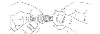
The fuel valve is equipped with a fuel sediment cup, screen, and o -ring that need to be cleaned.
- Move fuel valve to “Off” position.
- Remove sediment cup (A) from fuel valve. Remove o- ring (B) and screen (C) from fuel valve.
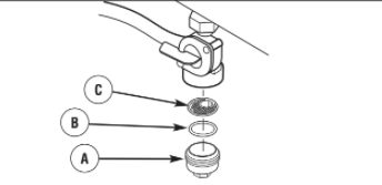
- Wash sediment cup, o -ring, and screen in a nonflammable solvent. Dry them thoroughly.
- Place screen and o -ring into fuel valve. Install sediment cup and tighten securely.
- Move fuel valve to “On” position, and check for leaks. Replace fuel valve if there is any leakage.
Engine Maintenance
WARNING Unintentional sparking could cause fire or electric shock resulting in death or serious injury.
WHEN ADJUSTING OR MAKING REPAIRS TO YOUR GENERATOR
• Disconnect the spark plug wire from the spark plug and place the wire where it cannot contact spark plug.
WHEN TESTING FOR ENGINE SPARK
• Use approved spark plug tester.
• DO NOT check for spark with spark plug removed.
Oil
Oil Recommendations
We recommend the use of Briggs & Stratton Warranty Certified oils for best performance. Other high-quality detergent oils are acceptable if classified for service SF, SG, SH, SJ or higher. DO NOT use special additives.
Outdoor temperatures determine the proper oil viscosity for the engine. Use the chart to select the best viscosity for the outdoor temperature range expected.
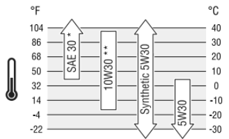
- Below 40°F (4°C) the use of SAE 30 will result in hard starting.
** Above 80°F (27°C) the use of 10W30 may cause increased oil consumption. Check oil level more frequently.
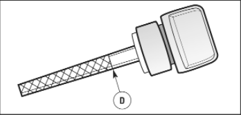
Checking Oil Level
Oil level should be checked prior to each use or at least every 8 hours of operation. Keep oil level maintained.
- Make sure generator is on a level surface.
- Clean area around oil fill, remove oil cap/dipstick and wipe dipstick with clean cloth. Replace dipstick. Remove and and check oil level.
NOTICE DO NOT screw in dipstick when checking oil level.
- Verify oil is at “Full” mark (D) on dipstick. Replace and tighten oil cap/dipstick.
Adding Engine Oil
- Make sure generator is on a level surface.
- Check oil level as described in Checking Oil Level.
- If needed, slowly pour oil into oil fill opening to the “Full” mark on dipstick. DO NOT overfill.
NOTICE Overfilling with oil could cause the engine to not start, or hard starting.
• DO NOT overfill.
• If over the FULL mark on dipstick, drain oil to reduce oil level to FULL mark on dipstick.
4.Replace and tighten oil cap/dipstick.
Changing Engine Oil
If you are using your generator under extremely dirty or dusty conditions, or in extremely hot weather, change the oil more often.
CAUTION Avoid prolonged or repeated skin contact with used motor oil.
• Used motor oil has been shown to cause skin cancer in certain laboratory animals.
• Thoroughly wash exposed areas with soap and water.
KEEP OUT OF REACH OF CHILDREN. DON’T POLLUTE. CONSERVE RESOURCES. RETURN USED OIL TO COLLECTION CENTERS.
Change the oil while the engine is still warm from running, as follows:
- Make sure unit is on a level surface.
- Disconnect the spark plug wire from the spark plug and place the wire where it cannot contact spark plug.
- Clean area around oil drain plug (A). The oil drain plug is located at base of engine, opposite carburetor.
- Remove oil drain plug and drain oil completely into a suitable container.
- Reinstall oil drain plug and tighten securely. Remove oil cap/dipstick.
- Slowly pour recommended oil (about 36 oz. (1.0 l)) into oil fill opening. Pause to permit oil to settle. Fill to “Full” mark on dipstick.
- Wipe dipstick clean each time oil level is checked. DO NOT overfill.
- Reinstall oil cap/dipstick. Tighten cap securely.
- Wipe up any spilled oil.
Service Air Cleaner
Your engine will not run properly and may be damaged if you run it with a dirty air cleaner. Clean or replace more often if operating under dusty or dirty conditions.
To service the air cleaner, follow these steps:
1.Loosen screws (B) and remove air cleaner cover (C).
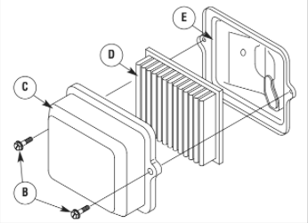
- Carefully remove cartridge (D) from base (E).
- Install clean (or new) air cleaner assembly inside cover. Dispose of old filter properly.
- Assemble air cleaner cover onto base and tighten screws.
Service Spark Plug
Changing the spark plug will help your engine to start easier and run better.
- Clean area around spark plug.
- Remove and inspect spark plug.
- Check electrode gap with wire feeler gauge and reset spark plug gap to recommended gap if necessary (see Specifications).
- Replace spark plug if electrodes are pitted, burned or porcelain is cracked. Use the recommended replacement spark plug. See Specifications.
- Install spark plug and tighten firmly.
Inspect Muffler and Spark Arrester
The engine exhaust muffler has a spark arrester screen. Inspect the muffler for cracks, corrosion, or other damage. Remove the spark arrester and inspect for damage or carbon blockage. If replacement parts are required, make sure to use only original equipment replacement parts.
WARNING Exhaust heat/gases could ignite combustibles, structures or damage fuel tank causing a fire, resulting in death or serious injury. Contact with muffler area could cause burns resulting in serious injury.
• DO NOT touch hot parts and AVOID hot exhaust gases.
• Allow equipment to cool before touching.
• Keep at least 5 feet (1.5 m) of clearance on all sides of generator including overhead.
• It is a violation of California Public Resource Code, Section 4442, to use or operate the engine on any forest-covered, brush-covered, or grass-covered land unless the exhaust system is equipped with a spark arrester, as defined in Section 4442, maintained in effective working order. Other states or federal jurisdictions may have similar laws. Contact the original equipment manufacturer, retailer, or dealer to obtain a spark arrester designed for the exhaust system installed on this engine.
• Replacement parts must be the same and installed in the same position as the original parts.
Clean and inspect the spark arrester as follows:
- To remove muffler heat shield (A) from muffler (B), remove four screws that connect guard to muffler bracket.
- Remove four screws that attach spark arrester screen (C).
- Inspect screen and obtain a replacement if torn, perforated or otherwise damaged. DO NOT use a defective screen. If screen is not damaged, clean it with commercial solvent.
- Reattach screen and muffler guard.
Clean Cooling System
Over time debris may accumulate in cylinder cooling fins and cannot be observed without partial engine disassembly. For this reason, we recommend you have a Briggs & Stratton authorized dealer clean the cooling system (D) per recommended intervals (see Maintenance Schedule in the Maintenance section). Equally important is to keep top of engine free from debris. Also see Cleaning.
Carburetor Adjustment
The carburetor on this engine is low emission. It is equipped with a non-adjustable idle mixture valve. Top speed has been set at the factory. If adjustment is required, see a Briggs & Stratton authorized dealer.
CAUTION Excessively high operating speeds could result in minor injury.
Excessively low speeds impose a heavy load.
• DO NOT tamper with governor spring, links or other parts to increase engine speed. Generator supplies correct rated frequency and voltage when running at governed speed.
• DO NOT modify generator in any way.
Storage
The generator should be started at least once every seven days and allowed to run at least 30 minutes. If this cannot be done and you must store the unit for more than 30 days, use the following guidelines to prepare it for storage.
Generator Storage
• Clean the generator as outlined in Cleaning.
• Check that cooling air slots and openings on generator are open and unobstructed.
NOTICE Store Extend-a-panel TM and accessory cord indoors only.
• Always wrap accessory cord on generator and store indoors when not in use.
• If storing generator outdoors, always remove Extend-a-panel TM and accessory cord and store indoors.
Long Term Storage Instructions
Fuel can become stale when stored over 30 days. Stale fuel causes acid and gum deposits to form in the fuel system or on essential carburetor parts. To keep fuel fresh, use Briggs & Stratton® Advanced Formula Fuel Treatment & Stabilizer, available wherever Briggs & Stratton genuine service parts are sold.
For engines equipped with a FRESH START® fuel cap, use Briggs & Stratton FRESH START® available in a drip concentrate cartridge.
There is no need to drain gasoline from the engine if a fuel stabilizer is added according to instructions. Run the engine for 2 minutes to circulate the stabilizer throughout the fuel system before storage.
If gasoline in the engine has not been treated with a fuel stabilizer, it must be drained into an approved container. Run the engine until it stops from lack of fuel. The use of a fuel stabilizer in the storage container is recommended to maintain freshness.
WARNING: Fuel and its vapors are extremely flammable and explosive which could cause burns, fire or explosion resulting in death or
serious injury.
WHEN STORING FUEL OR EQUIPMENT WITH FUEL IN TANK
• Store away from furnaces, stoves, water heaters, clothes dryers or other appliances that have pilot light or other ignition source because they could ignite fuel vapors.
WHEN DRAINING FUEL
• Turn generator engine OFF and let it cool at least 2 minutes before removing fuel cap. Loosen cap slowly to relieve pressure in tank.
• Drain fuel tank outdoors.
• Keep fuel away from sparks, open flames, pilot lights, heat, and other ignition sources.
• Check fuel lines, tank, cap and fittings frequently for cracks or leaks. Replace if necessary.
• DO NOT light a cigarette or smoke.
Troubleshooting
| Problem | Cause | Correction |
| Engine is running, but no AC output is available. | 1. One of the circuit breakers is open. 2. Fault in generator. 3. Poor connection or defective cord set. 4. Connected device is bad. | 1. Reset circuit breaker. 2. Contact authorized service facility. 3. Check and repair. 4. Connect another device that is in good condition. |
| Engine runs well at no-load but “bogs down” when loads are connected. | 1. Short circuit in a connected load. 2. Engine speed is too slow. 3. Generator is overloaded. 4. Shorted generator circuit. | 1. Disconnect shorted electrical load. 2. Contact authorized service facility. 3. See Don’t Overload Generator. 4. Contact authorized service facility. |
| Engine will not start; starts and runs rough or shuts down when running. | 1. On/Off switch set to off position (O). 2. Fuel valve is in “Off” position. 3. Failed battery. 4. Low oil level. 5. Dirty air cleaner. 6. Out of fuel. 7. Stale fuel. 8. Spark plug wire not connected to spark plug. 9. Bad spark plug. 10. Water in fuel. 11. Flooded. 12. Excessively rich fuel mixture. 13. Intake valve stuck open or closed. 14. Engine has lost compression. 15. Clogged carbon canister. | 1. Set switch to on position (I). 2. Turn fuel valve to “On” position. 3. Replace battery. 4. Fill crankcase to proper level or place generator on level surface. 5. Clean or replace air cleaner. 6. Fill fuel tank. 7. Drain fuel tank and carburetor; fill with fresh fuel. 8. Connect wire to spark plug. 9. Replace spark plug. 10. Drain fuel tank and carburetor; fill with fresh fuel. 11. Wait 5 minutes and re-crank engine. 12. Contact authorized service facility. 13. Contact authorized service facility. 14. Contact authorized service facility. 15. Replace carbon canister. |
| Engine lacks power. | 1. Load is too high. 2. Dirty air filter. | 1. See Don’t Overload Generator. 2. Replace air filter. |
| Engine “hunts” or falters. | Carburetor is running too rich or too lean. | Contact authorized service facility. |
Warranties
California, U.S. EPA, and Briggs & Stratton Corporation Emissions Control Warranty Statement
Your Warranty Rights And Obligations
The California Air Resources Board, U.S. EPA, and Briggs & Stratton (B&S) are pleased to explain the emissions control system warranty
on your Model Year 2012-2013 engine/equipment. In California, new small off-road engines and large spark ignited engines less than or
equal to 1.0 liter must be designed, built, and equipped to meet the State’s stringent anti-smog standards. B&S must warrant the
emissions control system on your engine/equipment for the periods of time listed below provided there has been no abuse, neglect, or
improper maintenance of your engine or equipment.
Your emissions control system may include parts such as the carburetor or fuel injection system, ignition system, and catalytic converter. Also included may be hoses, belts, connectors, sensors, and other emissions-related assemblies. Your evaporative emission control system may include parts such as: carburetors, fuel tanks, fuel lines, fuel caps, valves, canisters, filters, vapor hoses, clamps, connectors, and other associated components. Where a warrantable condition exists, B&S will repair your engine/equipment at no cost to you including diagnosis, parts, and labor.
Manufacturer’s Warranty Coverage:
Small off-road engines and large spark ignited engines less than or equal to 1.0 liter, and any emissions related components of the
equipment, are warranted for two years*. If any emissions-related part on your engine/equipment is defective, the part will be repaired
or replaced by B&S.
- Two years or for the time period listed in the respective engine or product warranty statement, whichever is greater.
Owner’s Warranty Responsibilities:
• As the engine/equipment owner, you are responsible for the performance of the required maintenance listed in your owner’s manual. B&S recommends that you retain all receipts covering maintenance on your engine/equipment, but B&S cannot deny warranty solely for the lack of receipts or your failure to ensure the performance of all scheduled maintenance.
• As the engine/equipment owner, you should however be aware that B&S may deny you warranty coverage if your engine/equipment or a part has failed due to abuse, neglect, improper maintenance, or unapproved modifications.
• You are responsible for presenting your engine/equipment to a B&S distribution center, servicing dealer, or other equivalent entity, as applicable, as soon as a problem exists. The warranty repairs should be completed in a reasonable amount of time, not to exceed 30 days. If you have any questions regarding your warranty rights and responsibilities, you should contact B&S at (414) 259-5262.
Briggs & Stratton Emissions Control Warranty Provisions
The following are specific provisions relative to your Emissions Control Warranty Coverage. It is in addition to the B&S engine warranty for non-regulated engines found in the Operator’s Manual.
- Warranted Emissions Parts
Coverage under this warranty extends only to the parts listed below (the emissions control systems parts) to the extent these parts were present on the B&S engine and/or B&S supplied fuel system.
a. Fuel Metering System
• Cold start enrichment system (soft choke)
• Carburetor and internal parts
• Fuel pump
• Fuel line, fuel line fittings, clamps
• Fuel tank, cap and tether
• Carbon canister
b. Air Induction System
• Air cleaner
• Intake manifold
• Purge and vent line
c. Ignition System
• Spark plug(s)
• Magneto ignition system
d. Catalyst System
• Catalytic converter
• Exhaust manifold
• Air injection system or pulse valve
e. Miscellaneous Items Used in Above Systems
• Vacuum, temperature, position, time sensitive valves and switches
• Connectors and assemblies
- Length of Coverage
For a period of two years from date of original purchase*, B&S warrants to the original purchaser and each subsequent purchaser that the engine is designed, built, and equipped so as to conform with all applicable regulations adopted by the Air Resources Board; that it is free from defects in material and workmanship that could cause the failure of a warranted part; and that it is identical in all material respects to the engine described in the manufacturer’s application for certification. The warranty period begins on the date the engine is originally purchased.
- Two years or for the time period listed in the respective engine or product warranty statement, whichever is greater.
The warranty on emissions-related parts is as follows:
• Any warranted part that is not scheduled for replacement as required maintenance in the owner’s manual supplied, is warranted for the warranty period stated above. If any such part fails during the period of warranty coverage, the part will be repaired or replaced by B&S at no charge to the owner. Any such part repaired or replaced under the warranty will be warranted for the remaining warranty period.
• Any warranted part that is scheduled only for regular inspection in the owner’s manual supplied, is warranted for the warranty period stated above. Any such part repaired or replaced under warranty will be warranted for the remaining warranty period.
• Any warranted part that is scheduled for replacement as required maintenance in the owner’s manual supplied, is warranted for the period of time prior to the first scheduled replacement point for that part. If the part fails prior to the first scheduled replacement, the part will be repaired or replaced by B&S at no charge to the owner. Any such part repaired or replaced under warranty will be warranted for the remainder of the period prior to the first scheduled replacement point for the part.
• Add on or modified parts that are not exempted by the Air Resources Board may not be used. The use of any non exempted add on or modified parts by the owner will be grounds for disallowing a warranty claim. The manufacturer will not be liable to warrant failures of warranted parts caused by the use of a non exempted add on or modified part.
- Consequential Coverage Coverage shall extend to the failure of any engine components caused by the failure of any warranted emissions parts.
- Claims and Coverage Exclusions
Warranty claims shall be filed according to the provisions of the B&S engine warranty policy. Warranty coverage does not apply to failures of emissions parts that are not original equipment B&S parts or to parts that fail due to abuse, neglect, or improper maintenance as set forth in the B&S engine warranty policy. B&S is not liable for warranty coverage of failures of emissions parts caused by the use of add-on or modified parts.
Look For Relevant Emissions Durability Period and Air Index Information On Your Small Off-Road Engine Emissions Label
Engines that are certified to meet the California Air Resources Board (CARB) small off-road Emissions Standard must display information regarding the Emissions Durability Period and the Air Index. Briggs & Stratton makes this information available to the consumer on our emissions labels. The engine emissions label will indicate certification information.
The Emissions Durability Period describes the number of hours of actual running time for which the engine is certified to be emissions
compliant, assuming proper maintenance in accordance with the Operating & Maintenance Instructions. The following categories are
used:
Moderate:
Engine is certified to be emissions compliant for 125 hours of actual engine running time.
Intermediate:
Engine is certified to be emissions compliant for 250 hours of actual engine running time.
Extended:
Engine is certified to be emissions compliant for 500 hours of actual engine running time.
For example, a typical walk-behind lawn mower is used 20 to 25 hours per year. Therefore, the Emissions Durability Period of an engine with an intermediate rating would equate to 10 to 12 years.
Briggs & Stratton engines are certified to meet the United States Environmental Protection Agency (USEPA) Phase 2 or Phase 3 emissions standards. The Emissions Compliance Period referred to on the Emissions Compliance label indicates the number of operating hours for which the engine has been shown to meet Federal emissions requirements.
For engines less than 225 cc displacement.
Category C = 125 hours
Category B = 250 hours
Category A = 500 hours
For engines of 225 cc or more displacement.
Category C = 250 hours
Category B = 500 hours
Category A = 1000 hours
LIMITED WARRANTY
Troy-Bilt® is a registered trademark of MTD Products Inc. and is used under license to Briggs & Stratton Power Products. Briggs & Stratton Power Products Group, LLC will repair or replace, free of charge, any part(s) of the portable generator that is defective in material or workmanship or both. Transportation charges on product submitted for repair or replacement under this warranty must be borne by purchaser. This warranty is effective for the time periods and subject to the conditions stated below. For warranty service, find the nearest Authorized Service Dealer in our dealer locator map at BRIGGSandSTRATTON.COM.
There is no other express warranty. Implied warranties, including those of merchantability and fitness for a particular purpose, are limited to one year from purchase, or to the extent permitted by law. All other implied warranties are excluded. Liability for incidental or consequential damages are excluded to the extent exclusion is permitted by law. Some states or countries do not allow limitations on how long an implied warranty lasts, and some states or countries do not allow the exclusion or limitation of incidental or consequential damages, so the above limitation and exclusion may not apply to you. This warranty gives you specific legal rights and you may also have other rights which vary from state to state or country to country.**
WARRANTY PERIOD
Consumer Use 2 years*
Commercial Use 1 year
In Australia – Our goods come with guarantees that cannot be excluded under the Australian Consumer Law. You are entitled to a replacement or refund for a major failure and for compensation for any other reasonably foreseeable loss or damage. You are also entitled to have the goods repaired or replaced if the goods fail to be of acceptable quality and the failure does not amount to a major failure. For warranty service, find the nearest Authorized Service Dealer in our dealer locator map at BRIGGSandSTRATTON.COM, or by calling 1300 274 447, or by emailing or writing to salesenquires@briggsandstratton.com.au, Briggs & Stratton Australia Pty Ltd, 1 Moorebank Avenue, NSW, Australia, 2170.
The warranty period begins on the date of purchase by the first retail end user, and continues for the period of time stated above. “Consumer Use” means personal residential household use by a retail consumer. “Commercial Use” means all other uses, including use for commercial, income producing or rental purposes. Once equipment has experienced commercial use, it shall thereafter be considered as commercial use for purposes of this warranty. Equipment used for prime power in place of utility are not applicable to this warranty.
NO WARRANTY REGISTRATION IS NECESSARY TO OBTAIN WARRANTY ON BRIGGS & STRATTON PRODUCTS. SAVE YOUR PROOF OF PURCHASE RECEIPT. IF YOU DO NOT PROVIDE PROOF OF THE INITIAL PURCHASE DATE AT THE TIME WARRANTY SERVICE IS REQUESTED, THE MANUFACTURING DATE OF THE PRODUCT WILL BE USED TO DETERMINE THE WARRANTY PERIOD.
ABOUT YOUR WARRANTY
We welcome warranty repair and apologize to you for being inconvenienced. Any Authorized Service Dealer may perform warranty repairs. Most warranty repairs are handled routinely, but sometimes requests for warranty service may not be appropriate. For example, warranty service would not apply if equipment damage occurred because of misuse, lack of routine maintenance, shipping, handling, warehousing or improper installation. Similarly, the warranty is void if the manufacturing date or the serial number on the portable generator has been removed or the equipment has been altered or modified. During the warranty period, the Authorized Service Dealer, at its option, will repair or replace any part that, upon examination, is found to be defective under normal use and service. This warranty will not cover the following repairs and equipment:
• Normal Wear: Outdoor Power Equipment, like all mechanical devices, needs periodic parts and service to perform well. This warranty does not cover repair when normal use has exhausted the life of a part or the equipment.
• Installation and Maintenance: This warranty does not apply to equipment or parts that have been subjected to improper or unauthorized installation or alteration and modification, misuse, negligence, accident, overloading, over speeding, improper maintenance, repair or storage so as, in our judgment, to adversely affect its performance and reliability. This warranty also does not cover normal maintenance such as air filters, adjustments, fuel system cleaning and obstruction (due to chemical, dirt, carbon, lime, and so forth).
• Other Exclusions: This warranty excludes wear items such as o- rings, filters, etc., or malfunctions resulting from accidents, abuse, modifications, alterations, or improper servicing or freezing or chemical deterioration. Accessory parts such as starting batteries, generator adapter cord sets and storage covers are excluded from the product warranty. This warranty excludes used, reconditioned, and demonstration equipment, equipment used for prime power in place of utility power, equipment used in life support applications, and failures due to acts of God and other force majeure events beyond the manufacturers control. 198185E, Rev. D, 10/5/2012
Portable Generator
Product Specifications
Starting Wattage . . . . . . . . . . . . . . . . . . . . . . .10,500 Watts
Wattage* . . . . . . . . . . . . . . . . . . . . . . . . . . . . . .7,000 Watts
AC Voltage . . . . . . . . . . . . . . . . . . . . . . . . . . .120/240 Volts
at 240 Volts . . . . . . . . . . . . . . . . . . . . . . . . . . .29.1 Amps
at 120 Volts . . . . . . . . . . . . . . . . . . . . . . . . . . .58.3 Amps
Frequency . . . . . . . . . . . . . . . . . . . . . . . .60 Hz at 3600 rpm
Phase . . . . . . . . . . . . . . . . . . . . . . . . . . . . . . . .Single Phase
Displacement . . . . . . . . . . . . . . . . . . .25.63 cu. in. (420 cc)
Spark Plug Gap . . . . . . . . . . . . . . . . . . .0.030 in. (0.76 mm)
Fuel Capacity . . . . . . . . . . . . .8.5 U.S. Gallons (32.2 Liters)
Oil Capacity . . . . . . . . . . . . . . . . . . . .36 Ounces (1.0 Liters
Common Service Parts
Air Cleaner . . . . . . . . . . . . . . . . . . . . . . . . . .491588 or 5043
Engine Oil Bottle . . . . . . . . . . . . . . . . . . . . . . . . . . . .100028
Synthetic Oil Bottle . . . . . . . . . . . . . . . . . . . . . . . . . .100074
Fuel Stabilizer . . . . . . . . . . . . . . . . . . . . .100120 or 100117
Spark Arrester . . . . . . . . . . . . . . . . . . . . . . . . . . . .83083GS
Power Ratings: The gross power rating for individual gas engine models is labeled in accordance with SAE (Society of Automotive Engineers) code J1940 (Small Engine Power & Torque Rating Procedure), and rating performance has been obtained and corrected in accordance with SAE J1995 (Revision 2002-05). Torque values are derived at 3060 RPM; horsepower values are derived at 3600 RPM. The gross power curves can be viewed at www.BRIGGSandSTRATTON.COM. Net power values are taken with exhaust and air cleaner installed whereas gross power values are collected without these attachments. Actual gross engine power will be higher than net engine power and is affected by, among other things, ambient operating conditions and engine-to-engine variability. Given the wide array of products on which engines are placed, the gas engine may not develop the rated gross power when used in a given piece of power equipment. This difference is due to a variety of factors including, but not limited to, the variety of engine components (air cleaner, exhaust, charging, cooling, carburetor, fuel pump, etc.), application limitations, ambient operating conditions (temperature, humidity, altitude), and engine-to-engine variability. Due to manufacturing and capacity limitations, Briggs & Stratton may substitute an engine of higher rated power for this Series engine. * This generator is rated in accordance with CSA (Canadian Standards Association) standard C22.2 No. 100-04 (motors and generators) and
PGMA (Portable Generator Manufacturers’ Association) standard PGMA G200 (Standard for Testing and Validating Performance of Portable Generators).
You can download the PDF version of the TROY BILT Portable Generator Operator’s Manual here.