FOR RESIDENTIAL USE ONLY
LiftMaster
300 Windsor Drive
Oak Brook, IL 60523
LiftMaster
300 Windsor Drive
Oak Brook, IL 60523
- Please read this manual and the safety materials carefully!
- The door WILL NOT CLOSE unless the Protector System® is connected and properly aligned. • Periodic checks of the garage door opener are required to ensure safe operation.
- This garage door opener is ONLY compatible with MyQ® and Security+ 2.0® accessories.
- DO NOT install on a one-piece door if using devices or features providing unattended close. Unattended devices and features are to be used ONLY with sectional doors.
- Attach warning labels to the location indicated on label.
Preparation
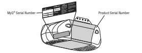
MyQ® Serial Number
Write down the following information for future reference:
MyQ® Serial Number:

Product Serial Number:

Date of Purchase:

Safety Symbol and Signal Word Review
This garage door opener has been designed and tested to offer safe service provided it is installed, operated, maintained and tested in strict accordance with the instructions and warnings contained in this manual.
When you see these Safety Symbols and Signal Words on the following pages, they will alert you to the possibility of serious injury or death if you do not comply with the warnings that accompany them. The hazard may come from something mechanical or from electric shock. Read the warnings carefully.


When you see this Signal Word on the following pages, it will alert you to the possibility of damage to your garage door and/or the garage door opener if you do not comply with the cautionary statements that accompany it. Read them carefully.

WARNING: This product can expose you to chemicals including lead, which are known to the State of California to cause cancer or birth defects or other reproductive harm. For more information go to www.P65Warnings.ca.gov
Unattended Operation
The Timer-to-Close (TTC) feature, the MyQ® Smartphone Control app, and MyQ® Garage Door and Gate Monitor are examples of unattended close and are to be used ONLY with sectional doors. Any device or feature that allows the door to close without being in the line of sight of the door is considered unattended close. The Timer-to-Close (TTC) feature, the MyQ® Smartphone Control, and any other MyQ® devices are to be used ONLY with sectional doors.
Preparation
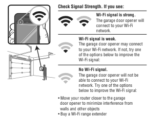
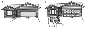
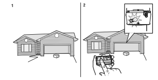
Test the Wi-Fi Signal Strength
Before You Begin:
You will need:
– Wi-Fi enabled smartphone, tablet or laptop
– Broadband Internet Connection
– Wi-Fi signal in the garage (2.4 Ghz, 802.11b/g/n required)
– Password for your home network (router’s main account, not guest network)
Test the Wi-Fi Signal Strength
Make sure your mobile device is connected to your Wi-Fi network. Hold your mobile device in the place where your garage door opener will be installed and check the Wi-Fi signal strength.
For compatible router specifications and help, visit WiFiHelp.LiftMaster.com.
See page 29 to connect the garage door opener to a mobile device.
Check the Door

– ALWAYS call a trained door systems technician if garage door binds, sticks, or is out of balance. An unbalanced garage door may NOT reverse when required.
– NEVER try to loosen, move or adjust garage door, door springs, cables, pulleys, brackets or their hardware, ALL of which are under EXTREME tension.
– Disable ALL locks and remove ALL ropes connected to garage door BEFORE installation and operating garage door opener to avoid entanglement.
– DO NOT install on a one-piece door if using devices or features providing unattended close. Unattended devices and features are to be used ONLY with
sectional doors.

– ALWAYS disable locks BEFORE installing and operating the opener.
– ONLY operate garage door opener at 120V, 60 Hz to avoid malfunction and damage.
Before you begin:
- Disable locks and remove any ropes connected to the garage door.
- Lift the door halfway up. Release the door. If balanced, it should stay in place, supported entirely by its springs.
- Raise and lower the door to check for binding or sticking.
If your door binds, sticks, or is out of balance, call a trained door systems technician. - Check the seal on the bottom of the door. Any gap between the floor and the bottom of the door must not exceed 1/4 inch (6 mm). Otherwise, the safety reversal system may not work properly.
- The opener should be installed above the center of the door. If there is a torsion spring or center bearing plate in the way of the header bracket, it may be installed within 4 feet (1.2 m) to the left or right of the door center. See page 9.

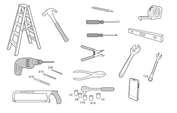
Tools Needed
Carton Inventory
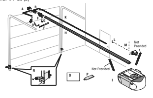
Accessories will vary depending on the garage door opener model purchased. Depending on your specific model, other accessories may be included with your garage door opener. The instructions for these accessories will be attached to the accessory and are not included in this manual. The images throughout this manual are for reference and your product may look different.
A. Header bracket
B. Pulley and bracket
C. Door bracket
D. Curved door arm
E. Straight door arm
F. Trolley
G. Emergency release rope and handle
H. Rail
I. Garage door opener
J. Sprocket cover
K. Chain
L. Door control
M. White and red/white wire
N. The Protector System®
Safety reversing sensors with white and white/black wire attached: Sending Sensor (1) Receiving Sensor (1) and Safety Sensor Brackets (2)
O. Safety labels and literature
P. Rail grease
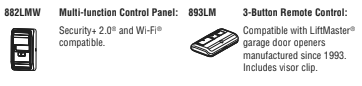
Security+ 2.0® Accessories
882LMW
Multi-Function Door Control
893LM
Remote Control

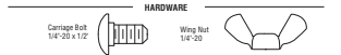
Hardware
Installation
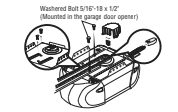
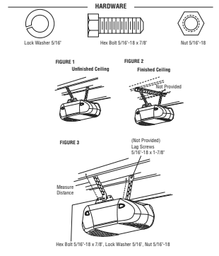
Hex bolt 5/16″-18 x 7/8″ (4)
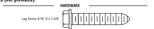
Lag screw 5/16″-9 x 1-5/8″ (2)
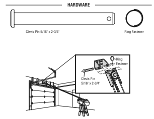
Clevis Pin 5/16″ x 2-3/4″ (1)
Clevis Pin 5/16″ x 1-1/4″ (1)
Clevis Pin 5/16″ x 1″ (1)
Nut 5/16″-18 (4)
Lock washer 5/16″ (4)
Self-threading screw 1/4″-14 x 5/8″ (2)
Ring fastener (3)
Carriage bolt 1/4″-20 x 1/2″ (2)
Wing nut 1/4″-20 (2)
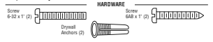
Door Control Hardware
Screw 6AB x 1″ (2)
Screw 6-32 x 1″ (2)
Drywall anchors (2)
Assembly
1 Attach the Rail to the Garage Door Opener

– ALWAYS keep hand clear of sprocket while operating opener.
– Securely attach sprocket cover BEFORE operating.

NOTE: ONLY use the bolts removed from the garage door opener. Place the garage door opener on the packing material to prevent scratching.
- Remove the two bolts from the top of the garage door opener.
- Align the rail and the styrofoam over the sprocket. Cut the tape from the rail, chain, and styrofoam.
- Fasten the rail with the previously removed bolts.
- Position the chain around the garage door opener sprocket.
- Install the sprocket cover by squeezing the sides and inserting the tabs into the slots on the garage door opener.
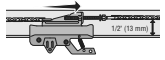
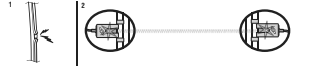
2 Tighten the Chain
- Loosen the inner nut and lock washer on the trolley threaded shaft.
- Tighten the outer nut until the chain is a 1/2 inch above the base of the rail at the midpoint of the rail.
- Re-tighten the inner nut.
Slack in the chain is normal when the door is closed. No readjustment is necessary.
Sprocket noise can result if the chain is too loose. During future maintenance, ALWAYS pull the emergency release handle to disconnect the trolley before adjusting the chain.
Installation
IMPORTANT INSTALLATION INSTRUCTIONS

To reduce the risk of SEVERE INJURY or DEATH:
- READ AND FOLLOW ALL INSTALLATION WARNINGS AND INSTRUCTIONS.
- Install garage door opener ONLY on properly balanced and lubricated garage door. An improperly balanced door may NOT reverse when required and could result in SEVERE INJURY or DEATH.
- ALL repairs to cables, spring assemblies and other hardware MUST be made by a trained door systems technician BEFORE installing opener.
- Disable ALL locks and remove ALL ropes connected to garage door BEFORE installing opener to avoid entanglement.
- Install garage door opener 7 feet (2.13 m) or more above floor.
- Mount the emergency release within reach, but at least 6 feet (1.83 m) above the floor and avoiding contact with vehicles to avoid accidental release.
- NEVER connect garage door opener to power source until instructed to do so.
- NEVER wear watches, rings or loose clothing while installing or servicing opener. They could be caught in garage door or opener mechanisms.
- Install wall-mounted garage door control:
– within sight of the garage door.
– out of reach of small children at a minimum height of 5 feet (1.5 m) above floors, landings, steps or any other adjacent walking surface.
-away from ALL moving parts of the door. - Place entrapment warning label on wall next to garage door control.
- Place manual release/safety reverse test label in plain view on inside of garage door.
- Upon completion of installation, test safety reversal system. Door MUST reverse on contact with a 1-1/2″ (3.8 cm) high object (or a 2×4 laid flat) on the
floor. - To avoid SERIOUS PERSONAL INJURY or DEATH from electrocution, disconnect ALL electric power BEFORE performing ANY service or maintenance.
- DO NOT install on a one-piece door if using devices or features providing unattended close. Unattended devices and features are to be used ONLY with
sectional doors.
NOTE: If you are installing the garage door opener on a one-piece door, visit LiftMaster.com for installation instructions.
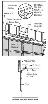
1 Determine the Header Bracket Location

– Header bracket MUST be RIGIDLY fastened to structural support on header wall or ceiling, otherwise garage door might NOT reverse when required. DO
NOT install header bracket over drywall.
– Concrete anchors MUST be used if mounting header bracket or 2×4 into masonry.
– NEVER try to loosen, move or adjust garage door, springs, cables, pulleys,
brackets, or their hardware, ALL of which are under EXTREME tension.
– ALWAYS call a trained door systems technician if garage door binds, sticks, or is out of balance. An unbalanced garage door might NOT reverse when
required.
– DO NOT enable the Timer-to-Close functionality if operating either one-piece or
swinging garage doors. To be enabled ONLY when operating a sectional door.
Close the door and mark the inside vertical centerline of the garage door.
Extend the line onto the header wall above the door. You can fasten the header bracket within 4 feet (1.22 m) of the left or right of the door center only if a torsion spring or center bearing plate is in the way; or you can attach it to the ceiling when clearance is minimal. (It may be mounted on the wall upside down if necessary, to gain approximately 1/2″ (1 cm). If you need to install the header bracket on a 2×4 (on wall or ceiling), use lag screws (not provided) to securely fasten the 2×4 to structural supports.
Open your door to the highest point of travel as shown. Draw an intersecting horizontal line on the header wall 2″ (5 cm) above the high point. This height will provide travel clearance for the top edge of the door.
NOTE: If the total number of inches exceeds the height available in your garage, use the maximum height possible, or refer to page 10 for ceiling installation.
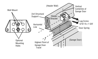
2 Install the Header Bracket
You can attach the header bracket either to the wall above the garage door, or to the ceiling. Follow the instructions which will work best for your particular requirements. Do not install the header bracket over drywall. If installing into masonry, use concrete anchors (not provided).
OPTION A – WALL INSTALLATION
- Center the bracket on the vertical centerline with the bottom edge of the bracket on the horizontal line as shown (with the arrow pointing toward the ceiling).
- Mark the vertical set of bracket holes (do not use the holes designated for ceiling mount). Drill 3/16″ pilot holes and fasten the bracket securely to a structural
support with lag screws.
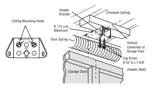
OPTION B – CEILING INSTALLATION
- Extend the vertical centerline onto the ceiling as shown.
- Center the bracket on the vertical mark, no more than 6″ (15 cm) from the wall. Make sure the arrow is pointing toward the wall. The bracket can be mounted
flush against the ceiling when clearance is minimal. - Mark the side holes. Drill 3/16″ pilot holes and fasten bracket securely to a structural support with the hardware provided.
3 Attach the Rail to the Header Bracket
- Align the rail with the header bracket. Insert the clevis pin through the holes in the header bracket and rail. Secure with the ring fastener.
NOTE: Use the packing material as a protective base for the garage door opener.
4 Position the Garage Door Opener

- Remove the packing material and lift the garage door opener onto a ladder.
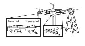
- Fully open the door and place a 2×4 (laid flat) under the rail.
A 2×4 is ideal for setting the distance between the rail and the door. If the ladder is not tall enough you will need help at this point. If the door hits the trolley when it is raised, pull the trolley release arm down to disconnect the inner and outer trolley. Slide the outer trolley toward the garage door opener. The trolley can remain disconnected until instructed.
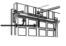
5 Hang the Garage Door Opener

installing ANY brackets into masonry.
Hanging your garage door opener will vary depending on your garage. Two representative installations are shown. Yours may be different. Hanging brackets should be angled (Figure 1) to provide rigid support. On finished ceilings (Figure 2), attach a sturdy metal bracket to structural supports before installing the opener. This bracket and fastening hardware are not provided.
- Measure the distance from each side of the motor unit to the structural support.
- Cut both pieces of the hanging bracket to required lengths.
- Drill 3/16″ pilot holes in the structural supports.
- Attach one end of each bracket to a support with 5/16″-18 x 1-7/8″ lag screws (not provided).
- Fasten the opener to the hanging brackets with 5/16″-18 x 7/8″ hex bolts, lock washers and nuts.
- Check to make sure the rail is centered over the door (or in line with the header bracket if the bracket is not centered above the door).
- Remove the 2×4. Operate the door manually. If the door hits the rail, raise the header bracket.
NOTE: DO NOT connect power to opener at this time.
6 Install the Light Bulbs

– DO NOT use short neck or specialty light bulbs.
– DO NOT use halogen bulbs. Use ONLY incandescent.
To prevent damage to the opener:
– DO NOT use bulbs larger than 100W.
– ONLY use A19 size bulbs.
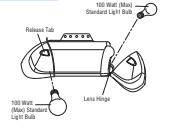
- Press the release tabs on both sides of lens. Gently rotate lens back and downward until the lens hinge is in the fully open position. Do not remove the
lens. - Install a 100 watt maximum light bulb in each socket. Light bulb size should be A19, standard neck only. The lights will turn ON and remain lit for approximately 4-1/2 minutes when power is connected. Then the lights will turn OFF.
- Reverse the procedure to close the lens.
NOTE: If the bulbs burn out prematurely due to vibration, replace with A19, standard neck garage door opener bulbs. The use of short neck or specialty light bulbs may overheat the endpanel or light socket.
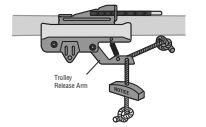
7 Attach the Emergency Release Rope and Handle

– If possible, use emergency release handle to disengage trolley ONLY when garage door is CLOSED. Weak or broken springs or unbalanced door could
result in an open door falling rapidly and/or unexpectedly.
– NEVER use emergency release handle unless garage doorway is clear of persons and obstructions.
– NEVER use handle to pull door open or closed. If rope knot becomes untied, you could fall.
- Insert one end of the emergency release rope through the handle. Make sure that “NOTICE” is right side up. Secure with an overhand knot at least 1″ (2.5 cm) from the end of the rope to prevent slipping.
- Insert the other end of the emergency release rope through the hole in the trolley release arm. Mount the emergency release within reach, but at least 6 feet (1.83m) above floor, avoiding contact with vehicles to prevent accidental release and secure with an overhand knot.
NOTE: If it is necessary to cut the emergency release rope, seal the cut end with a match or lighter to prevent unraveling. Ensure the emergency release rope and handle are above the top of all vehicles to avoid entanglement.
8 Install the Door Bracket

installing dealer for opener reinforcement instructions or reinforcement kit. Failure to
reinforce the top section as required according to the door manufacturer may void the door warranty.
A horizontal and vertical reinforcement is needed for lightweight garage doors (fiberglass, aluminum, steel, doors with glass panel, etc.) (not
provided). A horizontal reinforcement brace should be long enough to be secured to two or three vertical supports. A vertical reinforcement
brace should cover the height of the top panel.
Contact the garage door manufacturer or installing dealer for opener reinforcement instructions or reinforcement kit.
NOTE: Many door reinforcement kits provide for direct attachment of the clevis pin and door arm. In this case you will not need the door bracket; proceed to the next step.
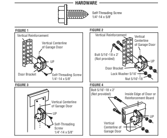
SECTIONAL DOORS
- Center the door bracket on the previously marked vertical centerline used for the header bracket installation. Note correct UP placement, as stamped inside the bracket.
- Position the top edge of the bracket 2″-4″ (5-10 cm) below the top edge of the door, OR directly below any structural support across the top of the door.
- Mark, drill holes and install as follows, depending on your door’s construction:
Metal or light weight doors using a vertical angle iron brace between the door panel support and the door bracket:
– Drill 3/16″ fastening holes. Secure the door bracket using the two self threading screws. (Figure 1)
– Alternately, use two 5/16″-18×2″ bolts, lock washers and nuts (not provided). (Figure 2)
Metal, insulated or light weight factory reinforced doors:
– Drill 3/16″ fastening holes. Secure the door bracket using the self-threading screws. (Figure 3)
Wood Doors:
– Use top and bottom or side to side door bracket holes. Drill 5/16” holes through the door and secure bracket with 5/16″-18 x 2″ carriage bolts, lock washers and
nuts (not provided). (Figure 4)
NOTE: The 1/4″-14 x 5/8″ self-threading screws are not intended for use on wood doors.
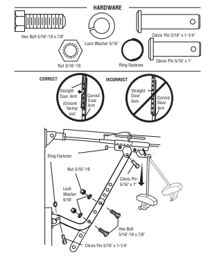
9 Connect the Door Arm to the Trolley
IMPORTANT: The groove on the straight door arm MUST face away from the curved door arm.
- Close the door. Disconnect the trolley by pulling the emergency release handle.
Slide the outer trolley back (away from the door) about 2″ (5 cm). - Attach the straight door arm to the outer trolley using the clevis pin. Attach with the ring fastener.
- Attach the curved door arm to the door bracket using the clevis pin. Attach with the ring fastener.
- Align the straight door arm with the curved door arm. Select two aligned holes (as far apart as possible) and attach using the bolts, nuts and lock washers.
NOTE: If the holes do not line up, reverse the straight door arm. Select two aligned holes (as far apart as possible) and attach using the bolts, nuts and lock washers. - Pull the emergency release handle toward the garage door opener until the trolley release arm is horizontal. The trolley will re-engage automatically when the garage door opener is activated.
Install the Door Control

– Be sure power is NOT connected BEFORE installing door control.
– Connect door control ONLY to 12 VOLT low voltage wires.
To prevent possible SERIOUS INJURY or DEATH from a closing garage door:
– Install door control within sight of garage door, out of reach of small children at a minimum height of 5 feet (1.5 m) above floors, landings, steps or any other adjacent walking surface, and away from ALL moving parts of door.
– NEVER permit children to operate or play with door control push buttons or remote control transmitters.
– Activate door ONLY when it can be seen clearly, is properly adjusted, and there are no obstructions to door travel.
– ALWAYS keep garage door in sight until completely closed. NEVER permit anyone to cross path of closing garage door.
INTRODUCTION
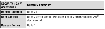
Compatible with MyQ® and Security+ 2.0® accessories, see page 37. Your garage door opener is compatible with up to 2 Smart Control Panels or 4 of any other Security+ 2.0® door controls. NOTE: Older LiftMaster door controls and third party products are not compatible.
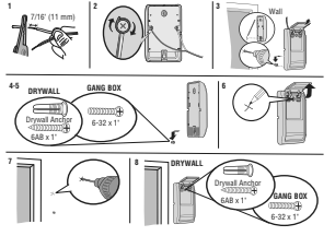
Install door control within sight of garage door, out of reach of small children at a minimum height of 5 feet (1.5 m) above floors, landings, steps or any other adjacent alking surface, and away from ALL moving parts of door. For gang box installations it is not necessary to drill holes or install the drywall anchors. Use the existing holes in the gang box.
NOTE: Your product may look different than the illustrations.
- Strip 7/16″ (11 mm) of insulation from one end of the wire and separate the wires.
- Connect one wire to each of the two screws on the back of the door control. The wires can be connected to either screw.
PRE-WIRED INSTALLATIONS: Choose any two wires to connect, note which wires are used so the correct wires are connected at the garage door opener in a
later step. - Mark the location of the bottom mounting hole and drill a 5/32″ hole.
- Install the bottom screw, allowing 1/8″ (3 mm) to protrude from the wall.
- Position the bottom hole of the door control over the screw and slide down into place.
- Lift the push bar up and mark the top hole.
- Remove the door control from the wall and drill a 5/32″ hole for the top screw.
- Position the bottom hole of the door control over the screw and slide down into place. Attach the top screw.
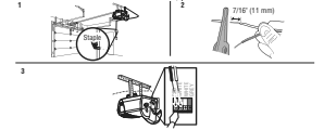
2 Wire the door control to the garage door opener
PRE-WIRED INSTALLATIONS: When wiring the door control to the garage door opener make sure you use the same wires that are connected to the door control.
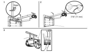
- Run the white and red/white wire from the door control to the garage door opener. Attach the wire to the wall and ceiling with staples (not applicable for
gang box or pre-wired installations). Do not pierce the wire with the staple as this may cause a short or an open circuit. - Strip 7/16 inch (11 mm) of insulation from the end of the wire near the garage door opener.
- Connect the wire to the red and white terminals on the garage door opener. To insert or release wires from the terminal, push in the tab with screwdriver tip.
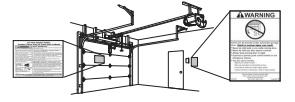
3 Attach the warning labels
- Attach the entrapment warning label on the wall near the door control with tacks or staples.
- Attach the manual release/safety reverse test label in a visible location on the inside of the garage door.
Install the Door Control
Introduction

To prevent SERIOUS INJURY or DEATH from closing garage door:
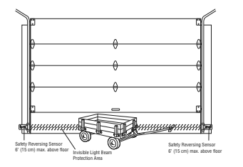
– Correctly connect and align the safety reversing sensor. This required safety device MUST NOT be disabled.
– Install the safety reversing sensor so beam is NO HIGHER than 6″ (15 cm) above garage floor.
IMPORTANT INFORMATION ABOUT THE SAFETY REVERSING SENSORS
The safety reversing sensors must be connected and aligned correctly before the garage door opener will move in the down direction.
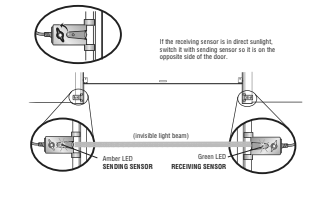
The sending sensor (with an amber LED) transmits an invisible light beam to the receiving sensor (with a green LED). If an obstruction breaks the light beam while the door is closing, the door will stop and reverse to the full open position, and the garage door opener lights will flash 10 times.
NOTE: For energy efficiency the garage door opener will enter sleep mode when the door is fully closed. The sleep mode shuts the garage door opener down until activated. The sleep mode is sequenced with the garage door opener light bulb; as the light bulb turns off the sensor LEDs will turn off and whenever the garage door opener lights turn on the sensor LEDs will light. The garage door opener will not go into the sleep mode until the garage door opener has completed 5 cycles upon power up.
When installing the safety reversing sensors check the following:
– Sensors are installed inside the garage, one on either side of the door.
– Sensors are facing each other with the lenses aligned and the receiving sensor lens does not receive direct sunlight.
– Sensors are no more than 6 inches (15 cm) above the floor and the light beam is unobstructed.
1 Install the Safety Reversing Sensors
The safety reversing sensors can be attached to the door track, the wall, or the floor. If the door track will not support the sensor bracket a wall installation is recommended.
Choose one of the following installations.
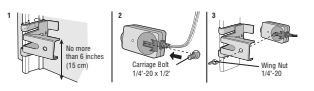
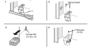
OPTION A – DOOR TRACK INSTALLATION
- Slide the curved arms of the sensor bracket around the edge of the door track.
Snap into place so that the sensor bracket is flush against the track. - Slide the carriage bolt into the slot on each sensor.
- Insert the bolt through the hole in the sensor bracket and attach with the wing nut. The lenses on both sensors should point toward each other. Make sure the lens is not obstructed by the sensor bracket.
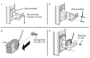
OPTION B – WALL INSTALLATION
If additional clearance is needed an extension bracket (not provided) or wood blocks can be used. Make sure each bracket has the same amount of clearance so they will align correctly.
- Position the sensor bracket against the wall with the curved arms facing the door.
Make sure there is enough clearance for the beam to be unobstructed. Mark holes. - Drill 3/16 inch pilot holes for each sensor bracket and attach the sensor brackets to the wall using lag screws (not provided).
- Slide the carriage bolt into the slot on each sensor.
- Insert the bolt through the hole in the sensor bracket and attach with the wing nut. The lenses on both sensors should point toward each other. Make sure the lens is not obstructed by the sensor bracket.
OPTION C – FLOOR INSTALLATION
Use an extension bracket (not provided) or wood block to raise the sensor bracket if needed.
- Carefully measure the position of both sensor brackets so they will be the same distance from the wall and unobstructed.
- Attach the sensor brackets to the floor using concrete anchors (not provided).
- Slide the carriage bolt into the slot on each sensor.
- Insert the bolt through the hole in the sensor bracket and attach with the wing nut. The lenses on both sensors should point toward each other. Make sure the lens is not obstructed by the sensor bracket.
2 Wire the Safety Reversing Sensors
PRE-WIRED INSTALLATIONS: If your garage already has wires installed for the safety reversing sensors, see page 21.
OPTION A – INSTALLATION WITHOUT PRE-WIRING
- Run the wire from both sensors to the garage door opener. Attach the wire to the wall and ceiling with staples.
- Strip 7/16 inch (11 mm) of insulation from each set of wires. Separate the wires.
Twist the white wires together. Twist the white/black wires together. - Insert the white wires into the white terminal on the garage door opener. Insert the white/black wires into the grey terminal on the garage door opener. To insert or remove the wires from the terminal, push in the tab with a screwdriver tip.
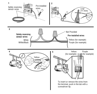
OPTION B – PRE-WIRED INSTALLATION
- Cut the end of the safety reversing sensor wire, making sure there is enough wire to reach the pre-installed wires from the wall.
- Separate the safety reversing sensor wires and strip 7/16 inch (11 mm) of insulation from each end. Choose two of the pre-installed wires and strip 7/16
inch (11 mm) of insulation from each end. Make sure that you choose the same color pre-installed wires for each sensor. - Connect the pre-installed wires to the sensor wires with wire nuts making sure the colors correspond for each sensor. For example, the white wire would
connect to the yellow wire and the white/black wire would connect to the purple wire. - At the garage door opener, strip 7/16 inch (11 mm) of insulation from each end of the wires previously chosen for the safety reversing sensors. Twist the like- colored wires together.
- Insert the wires connected to the white safety sensor wires to the white terminal on the garage door opener. Insert the wires that are connected to the white/black safety sensor wires to the grey terminal on the garage door opener.
Power
1 Connect Power

– Be sure power is NOT connected to the opener, and disconnect power to circuit BEFORE removing cover to establish permanent wiring connection.
– Garage door installation and wiring MUST be in compliance with ALL local electrical and building codes.
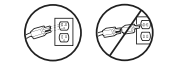
– NEVER use an extension cord, 2-wire adapter, or change plug in ANY way to make it fit outlet. Be sure the opener is grounded.
To avoid installation difficulties, do not activate the garage door opener at this time.
To reduce the risk of electric shock, your garage door opener has a grounding type plug with a third grounding pin. This plug will only fit into a grounding type outlet. If the plug doesn’t fit into your outlet, contact a qualified electrician to install the proper outlet.
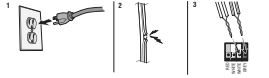
THERE ARE TWO OPTIONS FOR CONNECTING POWER:
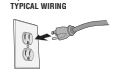
OPTION A – TYPICAL WIRING
- Plug in the garage door opener into a grounded outlet.
- DO NOT run garage door opener at this time.
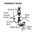
OPTION B – PERMANENT WIRING
If permanent wiring is required by your local code, refer to the following procedure. To make a permanent connection through the 7/8 inch hole in the top
of the motor unit (according to local code):
- Remove the motor unit cover screws and set the cover aside.
- Remove the attached 3-prong cord.
- Connect the black (line) wire to the screw on the brass terminal; the white (neutral) wire to the screw on the silver terminal; and the ground wire to the green
ground screw. The opener must be grounded. - Reinstall the cover.
2 Ensure the Safety Reversing Sensors are Aligned
The door will not close if the sensors have not been installed and aligned correctly.
When the light beam is obstructed or misaligned while the door is closing, the door will reverse and the garage door opener lights will flash ten times. If the door is already open, it will not close. The sensors can be aligned by loosening the wing nuts, aligning the sensors, and tightening the wing nuts.
- Check to make sure the LEDs in both sensors are glowing steadily. The LEDs in both sensors will glow steadily if they are aligned and wired correctly.
IF THE AMBER LED ON THE SENDING SENSOR IS NOT GLOWING:
- Make sure there is power to the garage door opener.
- Make sure the sensor wire is not shorted/broken.
- Make sure the sensor has been wired correctly: White wires to white terminal and white/black wires to gray terminal.
IF THE GREEN LED ON THE RECEIVING SENSOR IS NOT GLOWING:
- Make sure the sensor wire is not shorted/broken.
- Make sure the sensors are aligned.
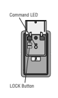
3 Ensure the Door Control is Wired Correctly
If the door control has been installed and wired correctly, the command LED behind the push bar will blink.
Adjustments
Introduction

– Incorrect adjustment of garage door travel limits will interfere with proper operation of safety reversal system.
– After ANY adjustments are made, the safety reversal system MUST be tested. Door MUST reverse on contact with 1-1/2″ (3.8 cm) high object (or 2×4 laid
flat) on floor.

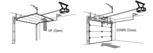
Your garage door opener is designed with electronic controls to make setup and adjustments easy. The adjustments allow you to program where the door will stop in the open (UP) and close (DOWN) position. The electronic controls sense the amount of force required to open and close the door. The force is adjusted automatically when you program the travel.
NOTE: If anything interferes with the door’s upward travel it will stop. If anything interferes with the door’s downward travel, it will reverse.
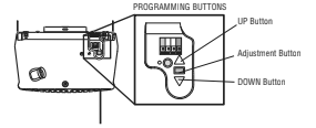
PROGRAMMING BUTTONS
The programming buttons are located on the back panel of the garage door opener and are used to program the travel. While programming, the UP and DOWN buttons can be used to move the door as needed.
To watch a video, go to youtu.be/Fyl1-SxQxnE
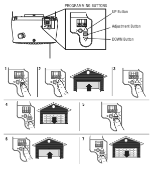
1 Program the Travel

– Incorrect adjustment of garage door travel limits will interfere with proper operation of safety reversal system.
– After ANY adjustments are made, the safety reversal system MUST be tested. Door MUST reverse on contact with 1-1/2″ (3.8 cm) high object (or 2×4 laid
flat) on floor.
While programming, the UP and DOWN buttons can be used to move the door as needed.
- Press and hold the Adjustment Button until the UP Button begins to flash and/or a beep is heard.
- Press and hold the UP Button until the door is in the desired UP position.
- Once the door is in the desired UP position press and release the Adjustment Button. The garage door opener lights will flash twice and the DOWN Button will begin to flash.
- Press and hold the DOWN button until the door is in the desired DOWN position.
- Once the door is in the desired DOWN position press and release the Adjustment Button. The garage door opener lights will flash twice and the UP Button will begin to flash.
- Press and release the UP Button. When the door travels to the programmed UP position, the DOWN Button will begin to flash.
- Press and release the DOWN Button. The door will travel to the programmed
DOWN position. Programming is complete.
If the garage door opener lights are flashing 5 times during the steps for Program the Travel, the programming has timed out. If the garage door opener lights are flashing 10 times during the steps for Program the Travel, the safety reversing sensors are misaligned or obstructed (refer to page 23). When the sensors are aligned and unobstructed, cycle the door through a complete up and down cycle using the remote control or the UP and DOWN buttons. Programming is complete. If you are unable to operate the door up and down, repeat the steps for Programming the Travel.
2 Test the Safety Reversal System

– Safety reversal system MUST be tested every month.
– After ANY adjustments are made, the safety reversal system MUST be tested.
Door MUST reverse on contact with 1-1/2″ (3.8 cm) high object (or 2×4 laid flat) on the floor.
- With the door fully open, place a 1-1/2 inch (3.8 cm) board (or a 2×4 laid flat) on the floor, centered under the garage door.
- Press the remote control push button to close the door. The door MUST reverse when it makes contact with the board.
If the door stops but does not reverse: - Review the installation instructions provided to insure all steps were followed;
- Repeat Program the Travel (see Adjustment Step 1);
- Repeat the Safety Reversal test. If the test continues to fail, call a trained door systems technician.
If the test continues to fail, call a trained door systems technician.
3 Test the Protector System®

- Open the door. Place the garage door opener carton in the path of the door.
- Press the remote control push button to close the door. The door will not move more than an inch (2.5 cm), and the garage door opener lights will flash 10 times.
The garage door opener will not close from a remote control if the LED in either safety reversing sensor is off (alerting you to the fact that the sensor is misaligned or obstructed). If the garage door opener closes the door when the safety reversing sensor is obstructed (and the sensors are no more than 6 inches [15 cm] above the floor), call for a trained door systems technician.
Operation
IMPORTANT SAFETY INSTRUCTIONS

To reduce the risk of SEVERE INJURY or DEATH:
- READ AND FOLLOW ALL WARNINGS AND INSTRUCTIONS.
- ALWAYS keep remote controls out of reach of children. NEVER permit children to operate or play with garage door control push buttons or remote controls.
- ONLY activate garage door when it can be seen clearly, it is properly adjusted, and there are no obstructions to door travel.
- ALWAYS keep garage door in sight and away from people and objects until completely closed. NO ONE SHOULD CROSS THE PATH OF THE MOVING DOOR.
- NO ONE SHOULD GO UNDER A STOPPED, PARTIALLY OPENED DOOR.
- If possible, use emergency release handle to disengage trolley ONLY when garage door is CLOSED. Use caution when using this release with the door
open. Weak or broken springs or unbalanced door could result in an open door falling rapidly and/or unexpectedly and increasing the risk of SEVERE
INJURY or DEATH. - NEVER use emergency release handle unless garage doorway is clear of persons and obstructions.
- NEVER use handle to pull garage door open or closed. If rope knot becomes untied, you could fall.
- After ANY adjustments are made, the safety reversal system MUST be tested.
- Safety reversal system MUST be tested every month. Garage door MUST reverse on contact with 1-1/2″ (3.8 cm) high object (or a 2×4 laid flat) on the floor. Failure to adjust the garage door opener properly increases the risk of SEVERE INJURY or DEATH.
- ALWAYS KEEP GARAGE DOOR PROPERLY BALANCED (see page 4). An improperly balanced door may NOT reverse when required and could result in
SEVERE INJURY or DEATH. - ALL repairs to cables, spring assemblies and other hardware, ALL of which are under EXTREME tension, MUST be made by a trained door systems technician.
- To avoid SERIOUS PERSONAL INJURY or DEATH from electrocution, disconnect ALL electric power BEFORE performing ANY service or maintenance.
- This operator system is equipped with an unattended operation feature. The door could move unexpectedly. NO ONE SHOULD CROSS THE PATH OF THE
MOVING DOOR. - DO NOT install on a one-piece door if using devices or features providing unattended close. Unattended devices and features are to be used ONLY with
sectional doors. - SAVE THESE INSTRUCTIONS.
Features
Your garage door opener is equipped with features to provide you with greater control over your garage door operation.
Alert2Close
The Alert2Close feature provides a visual and an audible alert that an unattended door is closing.
TIMER-TO-CLOSE (TTC)
The TTC feature automatically closes the door after a specified time period that can be adjusted using a TTC enabled door control (Models 881LMW or 880LMW). Prior to and during the door closing the garage door opener lights will flash and the garage door opener will beep.
MyQ®
MyQ® technology uses a 900MHz signal to provide two-way communication between the garage door opener and MyQ® enabled accessories. Your garage door opener is compatible with up to 16 MyQ® accessories.
SECURITY+ 2.0® REMOTE CONTROLS AND DOOR CONTROLS
Your garage door opener has already been programmed at the factory to operate with your remote control, which changes with each use, randomly accessing over 100 billion new codes. Compatible with MyQ® and Security+ 2.0® accessories, see page 37.
NOTE: Older LiftMaster remote controls, door controls, and third party products are not compatible.
THE PROTECTOR SYSTEM® (SAFETY REVERSING SENSORS)
When properly connected and aligned, the safety reversing sensors will detect an obstruction in the path of the infrared beam. If an obstruction breaks the infrared beam while the door is closing, the door will stop and reverse to full open position, and the opener lights will flash 10 times. If the door is fully open, and the safety reversing sensors are not installed, or are misaligned, the door will not close from a remote control. However, you can close the door if you hold the button on the door control or keyless entry until the door is fully closed. The safety reversing sensors do not effect the opening cycle.
ENERGY CONSERVATION
For energy efficiency the garage door opener will enter sleep mode when the door is fully closed. The sleep mode shuts the garage door opener down until activated. The sleep mode is sequenced with the garage door opener light bulb; as the light bulb turns off the sensor LEDs will turn off and whenever the garage door opener lights turn on the sensor LEDs will light. The garage door opener will not go into the sleep mode until the garage door opener has completed 5 cycles upon power up.
LIGHTS
The garage door opener light bulbs will turn on when the opener is initially plugged in; power is restored after interruption, or when the garage door opener is activated. The lights will turn off automatically after 4-1/2 minutes. Use an incandescent A19 light bulb (100 watt maximum).
Light Feature
The garage door opener is equipped with an added feature; the lights will turn on when someone enters through the open garage door and the safety reversing sensor infrared beam is broken. For added control over the light bulbs on your garage door opener, see page 31.
USING YOUR GARAGE DOOR OPENER
The garage door opener can be activated through a wall-mounted door control, remote control, wireless keyless entry or MyQ® accessory. When the door is closed and the garage door opener is activated the door will open. If the door senses an obstruction or is interrupted while opening the door will stop. When the door is in any position other than closed and the garage door opener is activated the door will close. If the garage door opener senses an obstruction while closing, the door will reverse. If the obstruction interrupts the sensor beam the garage door opener lights will blink 10 times. However, you can close the door if you hold the button on the door control or keyless entry until the door is fully closed. The safety reversing sensors do not affect the opening cycle.
The safety reversing sensor must be connected and aligned correctly before the garage door opener will move in the down direction.
Connect With Your Smartphone
The Wi-Fi® Garage Door Opener is compatible with up to 16 MyQ enabled accssories. Up to 10 devices can be paired to the Wi-Fi garage door opener’s internal gateway. These devices can be controlled with the MyQ app. These devices include any combination of MyQ garage door openers, Wi-Fi garage door openers, MyQ light controls, MyQ gate operators or MyQ commercial door operators. A LiftMaster Internet Gateway (828LM) can be added if you need to control more than 10 devices using the MyQ app. Up to 6 devices can be paired to garage door opener itself (controlled by garage door opener through 900MHz). These devices include any combination of MyQ light controls or a garage door and gate monitor.
You will need:
– Wi-Fi enabled smartphone, tablet or laptop
– Broadband Internet Connection
– Wi-Fi signal in the garage (2.4 Ghz, 802.11b/g/n required), see 4
– Password for your home network (router’s main account, not guest network)
– MyQ® serial number located on the garage door opener
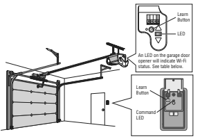
Connect Your Garage Door Opener to Your Home Wi-Fi Network
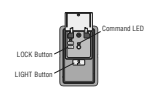
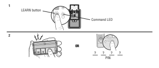
- Lift the push bar on the door control. Press and release the LEARN button OR press and release the yellow LEARN button on the garage door opener 3 times.
The garage door opener will beep once and the command LED on the door control will blink to indicate Wi-Fi learn mode. You have 20 minutes to complete
the connection process. - On your mobile device, go to Settings > Wi-Fi and select the network with the “MyQ-” prefix.
- Launch the web browser on your smartphone or tablet. Enter setup.myqdevice.com into the browser address bar. Follow the on screen prompts to connect the garage door opener to your Wi-Fi network. The MyQ serial number will display on screen.
Write the serial number in the space below.

- Download the MyQ app from the App Store® or Google PlayTM store. Sign up for your MyQ account and add the MyQ serial number to your account.
To add a second Wi-Fi garage door opener, repeat steps 1-3. Add the second MyQ serial number to your account in the MyQ app.
| LED | Definition |
| Blue | Off – Wi-Fi is not turned on. Blinking – Garage door opener is in Wi-Fi learn mode. Solid – Mobile device connected to the garage door opener. |
| Blue and Green | Blinking – Attempting to connect to router |
| Green | Blinking – Attempting to connect to the Internet server. Solid – Wi-Fi has been set up and garage door opener is connected to the internet. |
NOTES: To erase the Wi-Fi settings, see 32.
If you need help adding devices to your MyQ account, or to learn more go to WiFiHelp.LiftMaster.com.
Using the Door Control
SYNCHRONIZE THE DOOR CONTROL
To synchronize the door control to the garage door opener, press the push bar until the garage door opener activates (it may take up to 3 presses). Test the door control by pressing the push bar, each press of the push bar will activate the garage door opener.
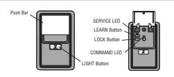
PUSH BAR
Press the push bar to open or close the door.
LIGHT BUTTON
Press the LIGHT button to turn the garage door opener lights on or off. When the lights are turned on they will stay on until the LIGHT button is pressed again, or until the garage door opener is activated. Once the garage door opener is activated the lights will turn off after the specified period of time (the factory setting is 4-1/2 minutes). The LIGHT button will not control the lights when the door is in motion.
The following features are accessible by lifting up the push bar:
LEARN A DEVICE
Any compatible remote controls, wireless keyless entry, or MyQ® accessories can be programmed to the garage door opener by pressing the LEARN button the door control, see page 32.
LOCK
The LOCK feature is designed to prevent activation of the garage door opener from remote controls while still allowing activation from the door control and keyless entry.
This feature is useful for added peace of mind when the home is empty (i.e. vacation).
AUTOMATIC LIGHT
Light Feature
The lights will turn on when someone enters through the open garage door and the safety reversing sensor infrared beam is broken.
MAINTENANCE ALERT (MAS)
This feature assists the homeowner in ensuring the garage door opener system stays in good working condition. When the garage door opener needs to be serviced (approximately 4500 garage door opener cycles) the command (yellow) and service (red) LEDs will begin to alternately flash back and forth. The factory setting for the MAS feature is off and can be activated at time of installation. Contact your installing dealer for service.
LOCK
Your remote controls will NOT work when LOCK mode is active however your keyless entry will still allow access to your garage.
Activate:
Press and hold the LOCK button for 2 seconds. The command LED will flash as long as the lock feature is activated and your handheld remote control will not
operate your door at this time.
Deactivate:
Press and hold the LOCK button again for 2 seconds. The command LED will stop flashing and normal operation will resume.
LIGHT
To change the amount of time the garage door opener lights will stay on:
Press and hold the LOCK button until the garage door opener lights flash.* The time interval is indicated by the number of flashes.
| Number of times garage door opener lights flash | Time the garage door opener light stays on |
| 1 | 1-1/2 Minutes |
| 2 | 2-1/2 Minutes |
| 3 | 3-1/2 Minutes |
| 4 | 4-1/2 Minutes |
To cycle through the time intervals repeat the step above.
- Approximately 10 seconds
LIGHT FEATURE (Default is Active)
Deactivate:
Press and hold the LIGHT button until the garage door opener lights turn on, then off again.*
Activate:
Start with the garage door opener lights on.
Press and hold the LIGHT button until the garage door opener lights turn off, then on again.*
If the command LED is continuously blinking, the LOCK feature needs to be deactivated.
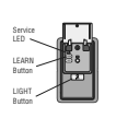
MAINTENANCE ALERT SYSTEM (MAS):
Activate/Deactivate:
Press and hold the LEARN button. Then press the LIGHT button. The service LED will flash the status; Active is 2 flashes and deactivated is 3 flashes.
Remote Control:
Your remote control has been programmed at the factory to operate with your garage door opener.
Older LiftMaster remote controls are NOT compatible, see page 37 for compatible accessories. Programming can be done through the door control or the learn button the garage door opener. To program additional accessories refer to the instructions provided with the accessory or visit LiftMaster.com. If your vehicle is equipped with a Homelink® you may require an external adapter depending on the make, model, and year of your vehicle. Visit www.homelink.com for additional information.
TO ADD, REPROGRAM, OR CHANGE A REMOTE CONTROL/KEYLESS ENTRY PIN USING THE DOOR CONTROL
- Press the LEARN button on the door control twice. The Command LED will blink.
2. Remote Control:
Press and release the button on the remote control that you wish to operate your garage door.
Keyless Entry:
Enter a 4-digit personal identification number (PIN) on the keypad. Then press the ENTER button.
The garage door opener lights will flash (or two clicks will be heard) and the Command LED will stop blinking when the code has been programmed. Repeat the steps above for programming additional remote controls or keyless entry devices. If programming is unsuccessful, program the remote using the learn button.
TO ADD, REPROGRAM, OR CHANGE A REMOTE CONTROL USING THE LEARN BUTTON
- Press and release the LEARN Button on the garage door opener.
- Press and hold the button on the remote control that you wish to use. Release the button when the garage door opener lights blink or two clicks are heard.
To Erase the Memory
ERASE ALL REMOTE CONTROLS AND KEYLESS ENTRIES
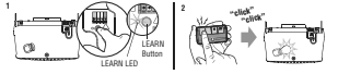
- Press and hold the LEARN button on garage door opener until the learn LED goes out (approximately 6 seconds). All remote control and keyless entry codes are now erased. Reprogram any accessory you wish to use.
ERASE ALL DEVICES (Including MyQ® enabled accessories)
- Press and hold the LEARN button on garage door opener until the learn LED goes out (approximately 6 seconds).
- Immediately press and hold the LEARN button again until the learn LED goes out. All codes are now erased. Reprogram any accessory you wish to use
ERASE THE Wi-Fi NETWORK FROM THE GARAGE DOOR OPENER
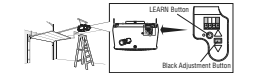
- Press and hold the black adjustment button on the garage door opener until 3 beeps are heard (Approximately 6 seconds).
ERASE A MyQ® ACCOUNT
Go to myLiftMaster.com to delete your MyQ account.
To Open the Door Manually

– If possible, use emergency release handle to disengage trolley ONLY when garage door is CLOSED. Weak or broken springs or unbalanced door could
result in an open door falling rapidly and/or unexpectedly.
– NEVER use emergency release handle unless garage doorway is clear of persons and obstructions.
– NEVER use handle to pull door open or closed. If rope knot becomes untied, you could fall.
DISCONNECT THE TROLLEY
- The door should be fully closed if possible.
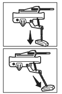
- Pull down on the emergency release handle.
RECONNECT THE TROLLEY
- The lockout feature prevents the trolley from reconnecting automatically.
- Pull the emergency release handle down and back (toward the opener). The door can then be raised and lowered manually as often as necessary.
- To disengage the lockout feature, pull the handle straight down. The trolley will reconnect on the next UP or DOWN operation, either manually or by using the door control or remote control.
Maintenance
Maintenance Schedule
EVERY MONTH
– Manually operate door. If it is unbalanced or binding, call a trained door systems technician.
– Check to be sure door opens and closes fully. Adjust if necessary, see page 25.
– Test the safety reversal system. Adjust if necessary, see page 26.
EVERY YEAR
– Oil door rollers, bearings and hinges. The garage door opener does not require additional lubrication. Do not grease the door tracks.
EVERY TWO TO THREE YEARS
– Use a rag to wipe away the existing grease from the garage door opener rail.
Reapply a small layer of white lithium grease to the top and underside of the rail surface where the trolley slides.
NOTICE: This device complies with Part 15 of the FCC rules and Industry Canada’s license-exempt RSSs. Operation is subject to the following two conditions: (1) this device may not cause harmful interference, and (2) this device must accept any interference received, including interference that may cause undesired operation.
Any changes or modifications not expressly approved by the party responsible for compliance could void the user’s authority to operate the equipment.
This device must be installed to ensure a minimum 20 cm (8 in.) distance is maintained between users/bystanders and device.
This device has been tested and found to comply with the limits for a Class B digital device, pursuant to part 15 of the FCC rules and Industry Canada ICES standard. These limits are designed to provide reasonable protection against harmful interference in a residential installation.
This equipment generates, uses and can radiate radio frequency energy and, if not installed and used in accordance with the instructions, may cause harmful interference to radio communications. However, there is no guarantee that interference will not occur in a particular installation. If this equipment does cause harmful interference to radio or television reception, which can be determined by turning the equipment off and on, the user is encouraged to try to correct the interference by one or more of the following measures:
– Reorient or relocate the receiving antenna.
– Increase the separation between the equipment and receiver.
– Connect the equipment into an outlet on a circuit different from that to which the receiver is connected.
– Consult the dealer or an experienced radio/TV technician for help.
The Remote Control Battery

– NEVER allow small children near batteries.
– If battery is swallowed, immediately notify doctor.
To reduce risk of fire, explosion or chemical burn:
– Replace ONLY with 3V CR2032 coin batteries.
– DO NOT recharge, disassemble, heat above 212°F (100°C) or incinerate.
To replace the battery, pry open the case in the middle, then at each side with the visor clip. Insert replacement battery positive side up (+). Replace the batteries with only 3V CR2032 coin cell
batteries. Dispose of old batteries properly.

Troubleshooting
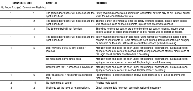
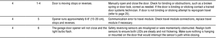
Diagnostic Chart
Your garage door opener is programmed with self-diagnostic capabilities. The UP and DOWN arrows on the garage door opener flash the diagnostic codes.
The garage door opener will NOT enter Wi-Fi® LEARN mode:
– After the initial installation of the garage door opener, the garage door opener must complete a full cycle (open and closed) before the Wi-Fi LEARN mode can
be activated.
– If there has been a recent power outage, the garage door opener must complete a full cycle before the Wi-Fi LEARN mode can be activated. See page 29 to activate Wi-Fi LEARN mode.
Cannot connect garage door opener to home Wi-Fi network:
– Ensure the MyQ Serial number was entered correctly and try again. The MyQ characters are between A-F and 0-9 only.
– Weak Wi-Fi signal in the garage. Ensure the Wi-Fi signal is reaching the garage, see page 4 or visit WiFiHelp.LiftMaster.com for more information.
My door will not close and the light bulbs blink on my motor unit:
The safety reversing sensor must be connected and aligned correctly before the garage door opener will move in the down direction.
– Verify the safety reversing sensors are properly installed, aligned and free of any obstructions.
My garage door opener light(s) will not turn off when the door is open:
The garage door opener is equipped with a feature that turns the light on when the safety reversing sensors have been obstructed. This feature can be disabled using the door control, see page 31.
My neighbor’s remote control opens my garage door:
Erase the memory from your garage door opener and reprogram the remote control(s).
My vehicle’s Homelink® is not programming to my garage door opener:
Depending on the make, model, and year of your vehicle an external adapter may be required. Visit www.homelink.com for additional information.
Accessories
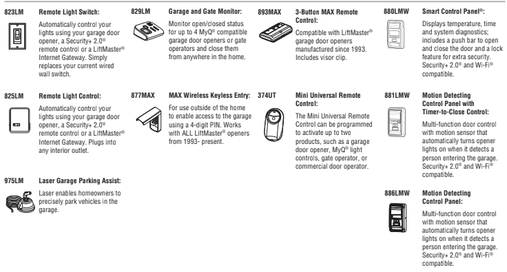
Provided Accessories
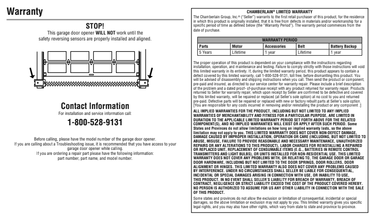
Warranty
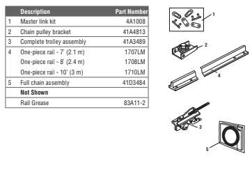
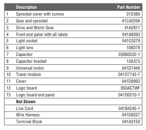
Repair Parts
Rail Assembly Parts
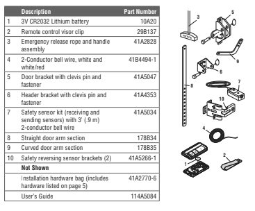
Installation Parts
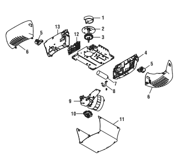
Garage Door Opener Parts
You can download PDF version of the LiftMaster Wi-Fi® Garage Door Opener User Manual (Premium Series Chain Drive Models 8365W and 8365W-267)