Package Includes:
• T4 Pro Thermostat
• UWPTM Mounting System
• Honeywell Standard Installation Adapter (J-box adapter)
• Honeywell Decorative Cover Plate – Small; size 4-49/64 in x 4-49/64 in x 11/32 in (121 mm x 121 mm x 9 mm)
• Screws and anchors
• 2 AA Batteries
• Installation Instructions and User Guide
Optional Cover Plate installation
NOTE: If Optional Cover Plate is not required, see “UWP Mounting System installation.”
Use the Optional Cover Plate when:
• Mounting the thermostat to an electrical junction box
• Or when you need to cover paint gap from old thermostat.
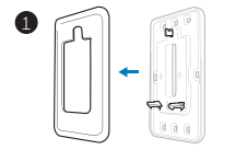
- Before starting, turn the power off at the breaker box or switch. Separate the Junction Box Adapter from the Cover Plate. See Figure 1.
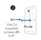
2. Mount the Junction Box Adapter to the wall or an electrical box using any of the eight screw holes. Insert and tighten mounting screws supplied with Cover
Plate Kit. Do not overtighten. See Figure 2. Make sure the Adapter Plate is level.
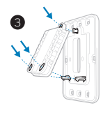
3. Attach the UWP by hanging it on the top hook of the Junction Box Adapter and then snapping the bottom of the UWP in place. See Figure 3.
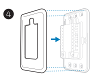
4. Snap the Cover Plate onto the Junction Box Adapter. See Figure 4.
UWP Mounting System installation
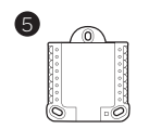
- Before starting, turn the power off at the breaker box or switch. Open package to find the UWP. See Figure 5.
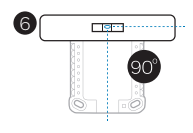
2. Position the UWP on wall. Level and mark hole positions. See Figure 6.
Drill holes at marked positions, and then lightly tap supplied wall anchors into the wall using a hammer.
‒ Drill 7/32” holes for drywall.
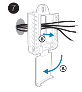
3. Pull the door open and insert the wires through wiring hole of the UWP. See Figure 7.
4. Place the UWP over the wall anchors.
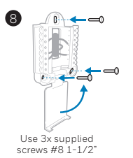
Insert and tighten mounting screws supplied with the UWP. Do not overtighten. Tighten until the UWP no longer moves. Close the door. See Figure 8.
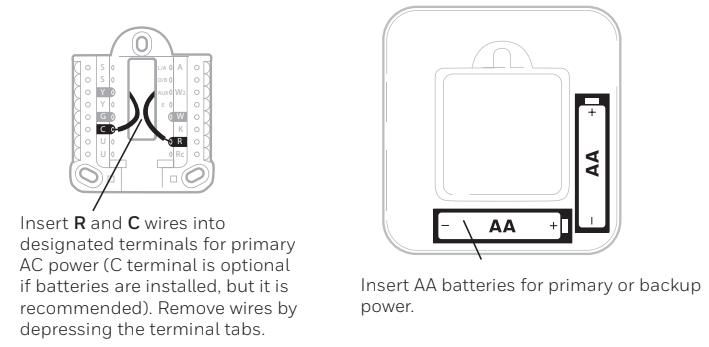
Power options
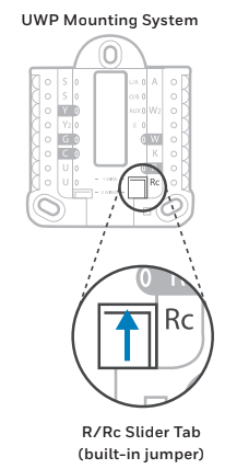
Setting Slider Tabs (built-in jumper)
Set R Slider Tab.
• Use built-in jumper (R Slider Tab) to differentiate between one or two transformer systems.
• If there is only one R wire, and it is connected to the R, Rc, or RH terminal, set the slider to the up position (1 wire).
• If there is one wire connected to the R terminal and one wire connected to the Rc terminal, set the slider to the down position (2 wires).
NOTE: Slider Tabs for U terminals should be left in place for T4 Pro models.
UWP Wiring terminal designations
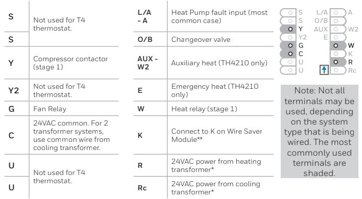
*Terminal can be jumped using Slider Tab. See “Setting Slider Tabs” above.
** The THP9045A1023 Wire Saver Module is used on heat/cool systems when you only have four wires at the thermostat, and you need a fifth wire for a common wire. Use the K terminal in place of the Y and G terminals on conventional or heat pump systems to provide control of the fan and the compressor through a single wire—the unused wire then becomes your common wire. See THP9045 instructions for more information.
Wiring conventional systems: forced air and hydronics
1H/1C System (1 transformer)
R Power [1]
Rc [R+Rc joined by Slider Tab] [2]
Y Compressor contactor
C 24VAC common [3]
W Heat relay
G Fan relay
Heat-only System
R Power [1]
Rc [R+Rc joined by Slider Tab] [2]
C 24VAC common [3]
W Heat relay
Heat-only System (Series 20) [5]
R Series 20 valve terminal “R” [1]
Rc [R+Rc joined by Slider Tab] [2]
Y Series 20 valve terminal “W”
C 24VAC common [3]
W Series 20 valve terminal “B”
Heat-only System
(power open zone valve) [5]
R Power [1]
Rc [R+Rc joined by Slider Tab] [2]
W Valve
C 24VAC common [3]
1H/1C System (2 transformers)
R Power (heating transformer) [1]
Rc Power (cooling transformer) [1]
Y Compressor contactor
C 24VAC common [3, 4]
W Heat relay
G Fan relay
Heat-only System with Fan
R Power [1]
Rc [R+Rc joined by Slider Tab] [2]
C 24VAC common [3]
W Heat relay
G Fan relay
Cool-only System
R Power [1]
Rc [R+Rc joined by Slider Tab] [2]
Y Compressor contactor
C 24VAC common [3]
G Fan relay
Wiring heat pump systems
1H/1C Heat Pump System
R Power [1]
Rc [R+Rc joined by Slider Tab] [2]
Y Compressor contactor
C 24VAC common [3]
O/B Changeover valve [7]
G Fan relay
2H/1C Heat Pump System (TH4210U only)
R Power [1]
Rc [R+Rc joined by Slider Tab] [2]
Y Compressor contactor
C 24VAC common [3]
O/B Changeover valve [7]
G Fan relay
AUX Auxiliary heat
E Emergency heat relay
L Heat pump fault input
NOTES
Wire specifications: Use 18- to 22-gauge thermostat wire. Shielded cable is not required.
[1] Power supply. Provide disconnect means and overload protection as required.
[2] Move R-Slider Tab on UWP to the R setting. For more information, see “Setting Slider Tabs (built-in jumper)”
[3] Optional 24VAC common connection.
[4] Common connection must come from cooling transformer.
[5] In ISU set Heat system type to Radiant Heat. Set number of cool stages to 0.
[7] In Installer Setup, set changeover valve to O (for cool changeover) or B (for heat changeover).
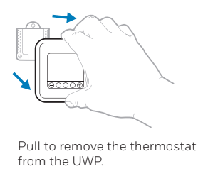
Thermostat mounting
- Push excess wire back into the wall opening.
- Close the UWP door. It should remain closed without bulging.
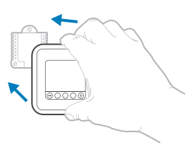
- Align the UWP with the thermostat, and push gently until the thermostat snaps in place.
- Turn the power on at the breaker box or switch.
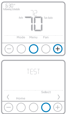
System operation settings
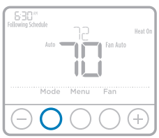
1 Press the Mode button to cycle to the next available System mode.
2 Cycle through the modes until the required System mode is displayed and leave it to activate.
NOTE: Available System modes vary by model and system settings.
System modes:
‒ Auto: Thermostat selects heating or cooling as needed.
‒ Heat: Thermostat controls only the heating system.
‒ Cool: Thermostat controls only the cooling system.
‒ Em Heat (TH4210U only) (only for heat pumps with auxiliary heat): Thermostat controls Auxiliary Heat. Compressor is not used.
‒ Off: Heating and cooling system is off. Fan will still operate if fan is set to On or Circulate.
Fan operation settings
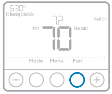
1 Press the Fan button to cycle to the next available Fan mode.
2 Cycle through the modes until the required Fan mode is displayed and leave it to activate.
NOTE: Available Fan modes vary with system settings.
Fan modes:
‒ Auto: Fan runs only when the heating or cooling system is on.
‒ On: Fan is always on.
Installer setup (ISU)
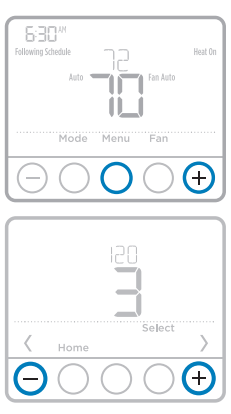
1 Press and hold CENTER and buttons for approximately 3 seconds to enter advanced menu.
2 Press Select to enter ISU.
3 Press Select to cycle through menu setup options.
4 Press or to change values or select from available options.
5 Press Select and confirm your settings or press Back to ignore changes and return to ISU menu screen to continue editing another setup option.
6 To finish setup process and save your setting, press Home and return to Home screen.
NOTE: A complete list of all setup (ISU) parameters and options starts below and continues through page 10.
Advanced setup options (ISU)
NOTE: Depending on system settings, not all options may be available.
| # ISU | ISU Name | ISU Options (factory default in bold) |
| 120 | Scheduling Options | 0 = Non-Programmable 2 = 5-2 Programmable 3 = 5-1-1 Programmable 4 = 7-Day Programmable Note: You can change default MO-FR, SA-SU schedule here. To edit periods during days, temperature setpoints, or to turn Schedule On/Off, touch MENU and go to SCHEDULE. |
| 125 | Temperature Indication Scale | 0 = Fahrenheit 1 = Celsius |
| 200 | Heating System Type | 1 = Conventional Forced Air Heat 2 = Heat Pump 3 = Radiant Heat 5 = None (Cool Only) Note: This option selects the basic system type your thermostat will control. |
| 205 | Heating Equipment Type | Conventional Forced Air Heat: 1 = Standard Efficiency Gas Forced Air 2 = High Efficiency Gas Forced Air 3 = Oil Forced Air 4 = Electric Forced Air 5 = Hot Water Fan Coil Heat Pump: 7 = Air to Air Heat Pump 8 = Geothermal Heat Pump Radiant Heat: 9 = Hot Water Radiant Heat 12 = Steam Note: This option selects the equipment type your thermostat will control. Note: This feature is NOT displayed if feature 200 is set to Cool Only. |
| # ISU | ISU Name | ISU Options (factory default in bold) |
| 218 | Reversing Valve O/B | 0 = O (O/B in Cool) 1 = B (O/B in Heat) Note: This option is only displayed if the Heat Pump configured. Select whether reversing valve O/B should energize in cool or in heat. |
| 220 | Cool Stages / Compressor Stages 200=Conv / 200=HP | 0, 1 Note: Select how many Cool or Compressor stages of your equipment the thermostat will control. Set value to 0 if you do not have Cool Stage/ Compressor Stage. |
| 221 | Heat Stages / Backup Heat Stages | 1Note: Select how many Heat or Aux/E stages of your equipment the thermostat will control. |
| 230 | Fan Control in Heat | 1 = Equipment Controls Fan 2 = Thermostat Controls Fan Note: This ISU is only displayed if ISU 205 is set to Electric Forced Air or Fan Coil. |
| 300 | System Changeover | 0 = Manual 1 = Automatic Note: Thermostat can automatically control both heating and cooling to maintain the desired indoor temperature. To be able to select “automatic” system mode on thermostat home screen, turn this feature ON. Turn OFF if you want to control heating or cooling manually. |
| 303 | Auto Changeover Differential | 0 °F to 5 °F 0.0 °C to 2.5 °C Note: Differential is NOT deadband. Differential means how far past the setpoint before switching to the mode selected. Deadband setup is not an option. Honeywell uses an advanced algorithm that fixes deadband at 0 °F. This is more advanced than previous thermostats. |
| 365 | Compressor Cycle Rate (Stage 1) | 1 – 6 Note: This ISU is only displayed when Cool /Compressor Stage is set to 1 stage. Cycle rate limits the maximum number of times the system can cycle in a 1 hour period measured at a 50% load. For example, when set to 3 CPH, at a 50% load, the most the system will cycle is 3 times per hour (10 minutes on, 10 minutes off). The system cycles less often when load conditions are less than or greater than a 50% load. |
| 370 | Heating Cycle Rate (Stage 1) | 1 – 12 Note: This ISU is only displayed when Heat Stage is set to 1 stage. Cycle rate limits the maximum number of times the system can cycle in a 1 hour period measured at a 50% load. For example, when set to 3 CPH, at a 50% load, the most the system will cycle is 3 times per hour (10 minutes on, 10 minutes off). The system cycles less often when load conditions are less than or greater than a 50% load. The recommended (default) cycle rate settings are below for each heating equipment type: Standard Efficiency Gas Forced Air = 5 CPH; High Efficiency Gas Forced Air = 3 CPH; Oil Forced Air = 5 CPH; Electric Forced Air = 9 CPH; Fan Coil = 3 CPH; Hot Water Radiant Heat = 3 CPH; Steam = 1 CPH. |
| 370 | Heating Cycle Rate Auxiliary Heat | 1 – 12 |
| 387 | Compressor Protection | 0 = Off 1 – 5 minutes Note: The thermostat has a built in compressor protection (minimum off timer) that prevents the compressor from restarting too early after a shutdown. The minimum-off timer is activated after the compressor turns off. If there is a call during the minimum-off timer, the thermostat shows “Wait” in the display. This ISU is displayed if ISU 220 is set to at least 1 stage. |
| 425 | Adaptive Intelligent Recovery | 0 = No 1 = Yes Note: Adaptive Intelligent Recovery (AIR) is a comfort setting. Heating or cooling equipment will turn on earlier, ensuring the indoor temperature will match the setpoint at the scheduled time. |
| 430 | Minimum Cool Setpoint | 50 °F to 99 °F (50 °F) 10.0 °C to 37.0 °C (10.0 °C) Note: The cool temperature cannot be set below this level. |
| 431 | Maximum Heat Setpoint | 40 °F to 90 °F (90 °F) 4.5 °C to 32.0 °C (32 °C) Note: The heat temperature cannot be set above this level. |
| # ISU | ISU Name | ISU Options (factory default in bold) |
| 435 | Keypad Lockout | 0 = None 1 = Partial 2 = Full Note: Unlocked: User has access to all thermostat settings. Partially Locked: User can modify only temperature settings. Fully Locked: User cannot modify any settings. Screen will be locked by default factory code and cannot be changed. This code is displayed for a short time, when you are about to lock the thermostat screen. Please note the code in safe place for future reference. |
| 702 | Number of Air Filters | 0 – 2 Note: This ISU refers to the number of air filters in the system. |
| 711 | Air Filter 1 Replacement Reminder | 0 = Off 10 = 45 Calendar Days 1 = 10 Run Time Days 11 = 60 Calendar Days 2 = 20 Run Time Days 12 = 75 Calendar Days 3 = 30 Run Time Days 13 = 3 Calendar Months 4 = 45 Run Time Days 14 = 4 Calendar Months 5 = 60 Run Time Days 15 = 5 Calendar Months 6 = 90 Run Time Days 16 = 6 Calendar Months 7 = 120 Run Time Days 17 = 9 Calendar Months 8 = 150 Run Time Days 18 = 12 Calendar Months 9 = 30 Calendar Days 19 = 15 Calendar Months Note: Set a reminder for when to change your air filter. Choose either calendar or equipment run time-based reminder. |
| 712 | Air Filter 2 Replacement Reminder | 0 = Off 10 = 45 Calendar Days 1 = 10 Run Time Days 11 = 60 Calendar Days 2 = 20 Run Time Days 12 = 75 Calendar Days 3 = 30 Run Time Days 13 = 3 Calendar Months 4 = 45 Run Time Days 14 = 4 Calendar Months 5 = 60 Run Time Days 15 = 5 Calendar Months 6 = 90 Run Time Days 16 = 6 Calendar Months 7 = 120 Run Time Days 17 = 9 Calendar Months 8 = 150 Run Time Days 18 = 12 Calendar Months 9 = 30 Calendar Days 19 = 15 Calendar Months Note: Set a reminder for when to change your air filter. Choose either calendar or equipment run time-based reminder. |
| 1400 | Backlighting | 0 = On Demand 1 = Continuous Note: Common wire needed for continuous. |
| 1401 | Backlight brightness | 1 – 5 Note: Only displayed if continuous backlight selected. |
| 1410 | Clock Format | 12 / 24 |
| 1415 | Daylight Saving Time | 0 = Off 1 = On Note: Set to Off in areas that do not follow Daylight Saving Time. |
| 1420 | Temperature Display Offset | -3 to 3F (0) -1.5 to 1.5C (0) Note: 0 °F – No difference in displayed temperature and the actual room temperature. The thermostat can display up to 3 °F (1.5 C) lower or higher than the actual measured temperature. |
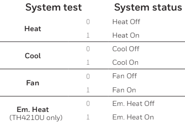
Installer system test
To perform a System Test:
1 Press and hold CENTER and buttons for approximately 3 seconds to enter advanced menu.
2 Use to go to TEST. Press Select to enter System Test.
3 Use to change between Heat, Cool, Fan, Em. Heat (TH4210U only), or Ver (thermostat version information). Press Select.
4 Press to turn heat, cool, or fan on. Press to turn them off.
5 Use the Home button to exit the System Test.
Specifications
Temperature Ranges
Heat: 40 °F to 90 °F (4.5 °C to 32.0 °C)
Cool: 50 °F to 99 °F (10.0 °C to 37.0 °C)
Operating Ambient Temperature
37 °F to 102 °F (2.8 °C to 38.9 °C)
Shipping Temperature
-20 °F to 120 °F (-28.9 °C to 48.9 °C)
Operating Relative Humidity
5% to 90% (non-condensing)
Physical Dimensions in inches (mm) (H x W x D)
4-1/16” H x 4-1/16” W x 1-5/32” D
103.5 mm H x 103.5 mm W x 29 mm D
Electrical Ratings
| Terminal | Voltage (50/60Hz) | Running Current |
| W Heating | 20-30 Vac | 0.02-1.0 A |
| (Powerpile) | 750 mV DC | 100 mA DC |
| W2 (Aux) Heating (TH4210U only) | 20-30 Vac | 0.02-1.0 A |
| E Emergency Heat (TH4210U only) | 20-30 Vac | 0.02-0.5 A |
| Y Compressor Stage 1 | 20-30 Vac | 0.02-1.0 A |
| G Fan | 20-30 Vac | 0.02-0.5 A |
| O/B Changeover | 20-30 Vac | 0.02-0.5 A |
| L/A Input | 20-30 Vac | 0.02-0.5 A |
CAUTION: ELECTRICAL HAZARD
Can cause electrical shock or equipment damage. Disconnect power before beginning installation.
CAUTION: EQUIPMENT DAMAGE HAZARD
Compressor protection is bypassed during testing. To prevent equipment damage, avoid cycling the compressor quickly.
CAUTION: MERCURY NOTICE
If this product is replacing a control that contains mercury in a sealed tube, do not place the old control in the trash. Contact your local waste management authority for instructions regarding recycling and proper disposal.
Customer assistance
For assistance with this product, please visit customer.honeywell.com.
Or call Honeywell Customer Care toll-free at 1-800-468-1502.
you can find download the PDF version of the Honeywell T4 Pro Programmable Thermostat Installation Instructions here.