Owner’s Manual & Safety Instructions
Save This Manual Keep this manual for the safety warnings and precautions, assembly, operating, inspection, maintenance and cleaning procedures. Write the product’s serial number in the back of the manual near the assembly diagram (or month and year of purchase if product has no number). Keep this manual and the receipt in a safe and dry place for future reference.
When unpacking, make sure that the product is intact and undamaged. If any parts are missing or broken, please call 1-888-866-5797 as soon as possible.
Copyright© 2012 by Harbor Freight Tools®. All rights reserved. No portion of this manual or any artwork contained herein may be reproduced in any shape or form without the express written consent of Harbor Freight Tools. Diagrams within this manual may not be drawn proportionally. Due to continuing improvements, actual product may differ slightly from the product described herein. Tools required for assembly and service may not be included.
WARNING: Read this material before using this product. Failure to do so can result in serious injury.
| WARNING SYMBOLS AND DEFINITIONS | |
| This is the safety alert symbol. It is used to alert you to potential personal injury hazards. Obey all safety messages that follow this symbol to avoid possible injury or death. | |
| DANGER | Indicates a hazardous situation which, if not avoided, will result in death or serious injury. |
| WARNING | Indicates a hazardous situation which, if not avoided, could result in death or serious injury. |
| CAUTION | Indicates a hazardous situation which, if not avoided, could result in minor or moderate injury. |
| NOTICE CAUTION | Addresses practices not related to personal injury. |
Important Safety Information
WARNING: Failure to follow the warnings and instructions may result in electric shock, fire and/or serious injury.
Installation Safety
- Keep children and bystanders away while installing the cameras. Distractions can cause you to lose control.
- Do not overreach when installing this product. Keep proper footing and balance at all times. This enables better control in unexpected situations.
- Wear ANSI-approved safety goggles during installation.
- This product is not a toy. Mount it out of reach of children.
Operation Safety
- Do not operate electrically powered products in explosive atmospheres, such as in the presence of flammable liquids, gases, or dust. Electrically
powered products create sparks which may ignite the dust or fumes. - The adapter must match the outlet. Never modify the plug in any way. Unmodified plugs and matching outlets will reduce risk of electric shock.
- Do not expose the Power Adapter of this product to rain or wet conditions. Water entering the Power Adapter will increase the risk of electric shock.
- Do not abuse the Power Cord. Never use the cord for unplugging the plug from the outlet. Keep cord away from heat, oil, sharp edges or moving
parts. Damaged or entangled cords increase the risk of electric shock.
- WARNING: The cord of this product contains lead and/or di (2-ethylhexyl) phthalate (DEHP), chemicals known to the State of California to cause cancer, and birth defects or other reproductive harm. Wash hands after handling. (California Health & Safety Code § 25249.5, et seq.)
- The warnings, precautions, and instructions discussed in this instruction manual cannot cover all possible conditions and situations that may occur. It must be understood by the operator that common sense and caution are factors which cannot be built into this product, but must be supplied by the operator.
Service Safety
- Product service must be performed only by a qualified technician.
- When servicing a product, use only identical replacement parts.
- Maintain this product with care. Keep this product clean. Do not use a damaged product. Tag damaged products “Do not use” until repaired.
- Disconnect the AC/DC Power Adapter from the power source before making any adjustments, changing accessories, or storing this product. Such preventive safety measures reduce the risk of electric shock.
- Maintain labels and nameplates on the unit. These carry important safety information. If unreadable or missing, contact Harbor Freight Tools for a replacement.
Grounding
WARNING: TO PREVENT ELECTRIC SHOCK AND DEATH FROM INCORRECT GROUNDING WIRE CONNECTION:
Check with a qualified electrician if you are in doubt as to whether the outlet is properly grounded. Do not modify the power cord plug provided with the system.
Never remove the grounding prong from the plug. Do not use the system if the power cord or plug is damaged. If damaged, have it repaired by a service facility before use. If the plug will not fit the outlet, have a proper outlet installed by a qualified electrician.
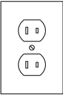
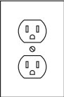
- The included adapter does not require grounding.
- The adapter may be used in either of the 120 volt outlets shown in the preceding illustration. (See Figure A.)
Extension Cords
Note: Do not use an extension cord with this item’s adapter.
Symbology

| V | Volts |
| ~ | Alternating Current |
| A | Amperes |
Specifications
| MONITOR | |
| Power Adapter Rating | 12VDC/1A |
| Screen Size | 4.3″ Diagonal |
| Color Configuration | RGB Delta |
| Resolution | 480 x 272 |
| Operating Temperature | 14º to 122º F |
| Operating Humidity | 85% Maximum |
| CAMERA | |
| Image Sensor | 1/4″ Color CMOS |
| Horizontal Resolution | 380 TVL |
| Effective Pixels | 658 x 492 |
| Focal Length | 6mm |
| Minimum Illumination | 1.0 lux without LED |
| Night Vision | Active (Illuminated) Infrared |
| Camera Input Rating | 12VDC / 200mA |
| Operating Temperature | - 4º to 122º F |
| Ingress Protection Rating | IP42 – Protected from vertically dripping water |
Setup
Read the ENTIRE IMPORTANT SAFETY INFORMATION section at the beginning of this manual including all text under subheadings therein before set up or use of this product.
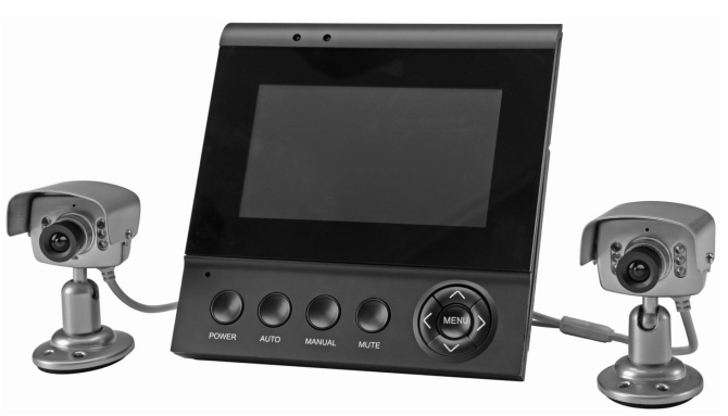
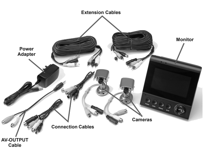
Components
Controls
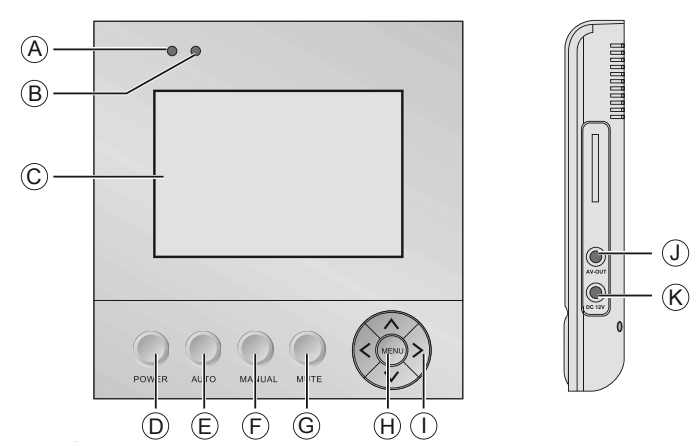
| A | Power Indicator | Red light indicates the system has power |
| B | System On/ Off Indicator | Blue light indicates the system is turned on |
| C | 4.3″ LCD | Monitor Screen |
| D | POWER | Power On/Off button |
| E | AUTO | Automatic continuous switching between the two camera views at preset intervals |
| F | MANUAL | Manual switching between the two camera views |
| G | MUTE | Audio On/Off Button |
| H | MENU | Scroll through and access Menus |
| I | < / > ˄ / ˅ | Left/Right and Up/Down buttons for navigating Menus |
| J | AV-OUT | Audio/Video Output to Monitor or Recording Device (not included) |
| K | DC 12V | 12VDC Input |
Connections
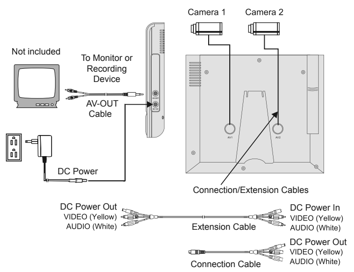
- Connect Cameras to Monitor:
a. Connect the cables on the Camera to the Extension cables.
b. Connect the Extension cables to the Connection cables.
c. Connect the Connection cables to AV1 and AV2 sockets on Monitor. - Connect the Power Adapter to the DC 12V input socket on Monitor. Plug the Power Adapter into a 120V grounded electrical outlet.
CAUTION! The Monitor and Power Adapter MUST be used indoors in a clean, dry location.
- Connect to Monitor or Recording Device: Use AV-OUT cable to connect unit to another device (not included).
NOTICE: CHECK FEDERAL, STATE AND LOCAL SURVEILLANCE LAWS BEFORE INSTALLING VIDEO AND/OR AUDIO SURVEILLANCE EQUIPMENT.
Camera Installation
IMPORTANT: Before mounting the cameras, connect all the cables and test the system to ensure unit and cameras are working properly. Test the cameras for the best location before installing.
NOTICE: When installing outdoors, mount Cameras under eaves, cameras are not weather proof. Protect connections from moisture with electrical tape.
- When planning the mounting location and angle of the Cameras, consider the following:
a. Do not mount the Cameras in bright or direct sunlight.
b. At night windows can reflect back into the Camera, interfering with the image. Test the Cameras in their intended location before mounting.
c. Choose locations high enough so that the Cameras are out of reach of children and others who might tamper with the units, but still cover the desired viewing areas adequately.
d. Take into consideration the length of the cables and the need to place the Monitor in a safe, dry location. Do not expose the Monitor to weather. - Route the AC/DC Adapter power cord and all cabling along a safe route without creating a tripping hazard or exposing the cord and cables to possible damage.
- Mount the Cameras to the chosen locations as follows:
a. Place the Bracket Base against the mounting surface and use mounting holes in the base as a template to mark the three points for drilling pilot holes.
WARNING! Verify that installation surface has no hidden utility lines or other wiring before drilling or driving screws.
b. Drill the pilot holes.
c. Mount the Cameras using three appropriate fasteners through the three holes in the Bracket Base of each Camera.
d. After the Cameras are mounted, run the cables to the Monitor.
e. Adjust the Cameras to cover the desired areas.
f. Once Cameras are installed, plug the cables into the Monitor.
Operating Instructions
Read the ENTIRE IMPORTANT SAFETY INFORMATION section at the beginning of this manual including all text under subheadings therein before set up or use of this product.
General Operating Instructions
- Peel off protective film covering monitor screen.
- Press the POWER switch on the Monitor to turn on the system. The camera’s view should appear on the screen.
- Press the AUTO button to select automatic switching from one camera view to the other.
- Press the MANUAL button to manually select between one camera view and the other.
- Press the MUTE button to turn the audio on or off.
- Use the MENU button and Left/Right () or Up/Down (˄/˅) buttons to make adjustments or change settings following guidelines in the MENU Settings section
- The system will operate continuously (day and night) while the AC/DC Power Adapter is plugged in and the system is turned on.
- When not using the system, unplug the Power Adapter from the electrical outlet.
MENU Settings
- Press the POWER switch to turn on the system. Press the MENU button to scroll through and access menus. (See Figure C on page 6 for control layout).
- To adjust picture quality:
a. Select the PICTURE menu using the MENU button.
b. Use the Up (˄) or Down (˅) buttons to select BRIGHT, CONTRAST, or COLOR.
c. Use the Left (<) or Right (>) buttons to adjust to the desired settings. - To adjust volume:
a. Select the VOLUME menu using the MENU button.
b. Use the Left (<) or Right (>) buttons to adjust volume to the desired level. - To adjust time interval in AUTO switch mode:
a. Select the OPTION menu using the MENU button.
b. Select the desired setting by using the Left (<) or Right (>) buttons to adjust the time interval from 5 to 99 seconds for automatic switching from one camera view to the other. - To select system video standard:
a. Select the SYSTEM menu using the MENU button.
b. Use the Left (<) or Right (>) buttons to select AUTO, PAL, NTSC, or SECAM. - To apply preset timer options:
a. Select the PRESET menu using the MENU button.
b. Use the Up (˄) or Down (˅) buttons to select SLEEP, TIME, OFF-TIME, or ON-TIME.

c. Use the Left (<) or Right (>) buttons to adjust to the desired settings.
Note: If power to the Monitor is cut off or the system is shut off any settings previously entered in the PRESET menu will be lost and the information will need to be re-entered.
Inspection, Maintenance, and Cleaning
Procedures not specifically explained in this manual must be performed only by a qualified technician.
WARNING:
TO PREVENT SERIOUS INJURY FROM ELECTRIC SHOCK: Unplug the Power Adapter from its electrical outlet before inspection, maintenance, or cleaning.
Monitor
- PERIODICALLY, inspect the general condition of the DVR. Check for:
• loose hardware,
• damaged cord/electrical wiring,
• cracked or broken parts, and
• any other condition that may affect its safe operation. - PERIODICALLY, wipe external surfaces with clean cloth.
Camera
- PERIODICALLY, inspect the general condition of the Camera. Check for:
• loose hardware,
• damaged cord/electrical wiring,
• cracked or broken parts, and
• any other condition that may affect its safe operation. - PERIODICALLY:
• Wipe external surfaces with clean cloth.
• Clean Camera lenses by applying lens cleaning solution to scratch-free cloth, then wiping lens. Do not apply solution directly to lenses. - Maintain area surrounding Camera, making sure obstacles don’t interfere with visibility, such as overgrown bushes
FCC STATEMENT
Note: This equipment has been tested and found to comply with the limits for a Class B digital device, pursuant to part 15 of the FCC Rules. These limits are
designed to provide reasonable protection against harmful interference in a residential installation. This equipment generates, uses and can radiate radio
frequency energy and, if not installed and used in accordance with the instructions, may cause harmful interference to radio communications. However, there is
no guarantee that interference will not occur in a particular installation.
If this equipment does cause harmful interference to radio or television reception, which can be determined by turning the equipment off and on, the user is encouraged to try to correct the interference by one or more of the following measures:
• Reorient or relocate the receiving antenna.
• Increase the separation between the equipment and receiver.
• Connect the equipment into an outlet on a circuit different from that to which the receiver is connected.
• Consult the dealer or an experienced radio/TV technician for help.
Limited 90 Day Warranty
Harbor Freight Tools Co. makes every effort to assure that its products meet high quality and durability standards, and warrants to the original purchaser that this product is free from defects in materials and workmanship for the period of 90 days from the date of purchase. This warranty does not apply to damage due directly or indirectly, to misuse, abuse, negligence or accidents, repairs or alterations outside our facilities, criminal activity, improper installation, normal wear and tear, or to lack of maintenance. We shall in no event be liable for death, injuries to persons or property, or for incidental, contingent, special or consequential damages arising from the use of our product. Some states do not allow the exclusion or limitation of incidental or consequential damages, so the above limitation of exclusion may not apply to you. THIS WARRANTY IS EXPRESSLY IN LIEU OF ALL OTHER WARRANTIES, EXPRESS OR IMPLIED, INCLUDING THE WARRANTIES OF MERCHANTABILITY AND FITNESS.
To take advantage of this warranty, the product or part must be returned to us with transportation charges prepaid. Proof of purchase date and an explanation of the complaint must accompany the merchandise. If our inspection verifies the defect, we will either repair or replace the product at our election or we may elect to refund the purchase price if we cannot readily and quickly provide you with a replacement. We will return repaired products at our expense, but if we determine there is no defect, or that the defect resulted from causes not within the scope of our warranty, then you must bear the cost of returning the product.
This warranty gives you specific legal rights and you may also have other rights which vary from state to state.
You can download the PDF version of the Bunker Hill Color Security System with night Vision User’s Manual here.