The (Chinese) Radio Documentation Project
http://radiodoc.github.com/
Lennart Lidberg
Baofeng UV-5R: The (Chinese) Radio Documentation Project: http://radiodoc.github.com/
by Lennart Lidberg Copyright © 2012 Lennart Lidberg
This work is licensed under the Creative Commons Attribution-ShareAlike 3.0 Unported License. You are free:
- To Share — to copy, distribute and transmit the work
- To Remix — to adapt the work
- To make commercial use of the work
Under the following conditions:
- Attribution — You must attribute the work in the manner specified by the author or licensor (but not in any way that suggests that they endorse you or your use of the work).
- Share Alike — If you alter, transform, or build upon this work, you may distribute the resulting work only under the same or similar license to this one.
With the understanding that:
- Waiver — Any of the above conditions can be waived if you get permission from the copyright holder.
- Public Domain — Where the work or any of its elements is in the public domain under applicable law, that status is in no way affected by the license.
- Other Rights — In no way are any of the following rights affected by the license:
- Your fair dealing or fair use rights, or other applicable copyright exceptions and limitations;
- The author’s moral rights;
- Rights other persons may have either in the work itself or in how the work is used, such as publicity or privacy rights.
To view a copy of this license, visit http://creativecommons.org/licenses/by-sa/3.0/
or send a letter to
Creative Commons,
559 Nathan Abbott Way,
Stanford, California 94305, USA.
All brand names and trademarks mentioned in this document is the property of their respective holders. The authors of this document shares no affiliation with any of the brands and trademarks mentioned within this document.
The (Chinese) Radio Documentation Project or its authors does not hold any responsibility or liability for any damage or injury, direct, indirect or otherwise caused as a result of following the instructions and procedures herein.
Commercial Radio Setup … Amateur Radio Setup
Preface
Lennart Lidberg November 10th, 2012.
Please excuse the crudity of this model. I didn’t have time to build it to scale or paint it. —Dr. Emmet Brown
This manual started out as a bit of a joke between friends, saying that “Someone should write a better manual!”. As it turns out, that someone turned out to be I.
Never having written any real documentation before (aside from short how-to documents online), I turned to the masters of documentation themselves for inspiration; O’Reilly Media and the Safari books. After reading around on their website I stumbled upon their design guideline documents, and in turn stumbled onto DocBook [http://docbook.org/] – an entire format designed for writing documentation – perfect.
As aresult this manual is a bit rough around the edges. A learning exercise using essen- tially defaults from the DocBookXSL stylesheet collection. However, despite not having the polish of a professional publication, the content should be the best it can be.
Many thanks to all of those who donated to make this possible. Also big thanks to O’Reilly Media for their inspiration and wonderful documentation.
Regarding CHIRP and the upcoming revised edition
Originally I intended to include a whole section in the programming chapter dedicated to the free and open source programming tool CHRIP [http://chirp.danplanet.com/], but unfortunately I couldn’t for the life of me get it playing with my hardware, despite trying three entirely different setups.
CHIRP will therefore have to wait for the revised edition of the book, which in turn will have to wait for me to get CHIRP working. Other than the addition of CHIRP and inclusion of any errata from this edition, the revised edition will include the Glossary and Index sections that were cut due to time concerns (unfortunately I didn’t have the foresight to index things as I was writing them as I was still learning about how to use DocBook). There is a high probability that I will further refine the book’s layout and design as well.
Part I. Getting started
Part one covers the basic setup and use of your hand-held two-way transceiver.
- Chapter 1, Initial setup
- Chapter 2, Getting to know your radio
- Chapter 3, Basic Use
Chapter 1. Initial setup
What’s in the box
This transceiver comes shipped with the following items in the box:
- Radio body
- Lithium-Ion battery pack
- Antenna
- Desk charger (With accompanying wall-wart)
- Optional belt clip
- Optional wrist-strap
Items included may vary depending on country of purchase. For further information please contact your local vendor or dealer.
Assembly
Before the radio is ready for use we need to attach the antenna and battery pack, as well as charge the battery.
Antenna
This transceiver is fitted with a Male SMA connector. To mount your antenna (Female SMA connector), align the two connectors and turn clockwise until it stops.
- Do not over-tighten your antenna to avoid damage to the connectors.
- When installing the antenna, don’t grip it by the top. Grip by the base and turn.
- If you use an external antenna, make sure the SWR is about 1.5:1 or lower to avoid damage to the transceiver.
- Do not hold the antenna with your hand or wrap the outside of it to avoid bad operation of the transceiver.
- Never transmit without an antenna.
Belt clip
At the back of the radio there are two parallel screws mounted above the battery, remove these and thread them through the holes on the belt clip as you screw them back into the radio body.
Do not use any form of glue to fix the screws on the battery clip. The solvents in the glue may cause damage to the battery casing.
Battery
Before attaching or removing the battery make sure your radio is turned off by turning the power/volume knob all the way counter-clockwise.
Installation
Make sure the battery is aligned in parallel with the radio body with the lower edge of the battery about 1-2cm below the edge of the radio.
Once aligned with the guide-rails, slide the battery upward until you hear a click as the battery locks in place.
Removal
To remove the battery, press the battery release above the battery pack (see Figure 2.1, “Baofeng UV-SR, overview”), as you slide the battery downward.
Charging and battery maintenance
For optimum battery efficiency, cycle the battery at least three times before regular use.
A cycle consists of fully charging the battery (about five hours charge time with a standard battery) and then fully depleting it before charging it again.
Charging
Follow these steps to hook up and use the charger:
- Plug the DC connector of the power adaptor into the charger base.
- Plug the AC connector of the power adaptor into a mains wall socket.
- Place the radio in the charging slot on the charger.
- Make sure the radio is making contact with the charger. When the the red LED comes on steady, your radio is charging.
- The radio is fully charged once the charger’s green status LED goes steady. Please remove the radio at that time to avoid over-charging your battery.
Table 1.1. Charger LED codes
| Red LED | Green LED | Status |
| Flashing | Steady | Standby (charger empty)Error (charger with radio) |
| Steady | Off | Charging |
| off | steady | Charge complete |
The charger and battery are fitted with matching notches so that you can charge your battery on its own! Practical if you have two batteries. That way you can charge one battery while still using your radio.
Battery Maintenance
The battery for your radio comes uncharged from the factory, please let it charge for at least Four to five hours before you start using your radio.
- Use only batteries approved by the original manufacturer.
- Never attempt to disassemble your battery pack.
- Do not expose your batteries to fire or intense heat.
- Dispose of batteries in accordance with local recycling regulations. Batteries do not belong in your trash can!
Prolonging the life of your battery
- Only charge batteries in normal room temperatures. When charging a battery attached to the radio, turn the radio off for a faster charge.
- Do not unplug the power to the charger or remove the battery and/or radio before it’s finished charging.
- Never charge a wet battery.
- Batteries wear out over time. If you notice a considerably shorter operating time with your radio, please consider purchasing a new battery.
- Battery performance will be reduced in temperatures below freezing. When working in cold environments, keep a spare battery on you. Preferably inside your jacket or in a similar location in order to keep the battery warm.
- Dust can interfere with the contacts on the battery. If necessary wipe the contacts with a clean cloth to ensure proper contact with radio and charger.
If your battery has become wet, remove it from the radio, wipe it dry with a towel and put it in a plastic bag with a handful of dry rice. Tie the bag up and let it sit over night. The rice will absorb any remaining moisture in the battery.
This method is only effective against minor splashes (light rain for instance). A soaked radio may very well be beyond repair.
Storage
Fully charge your battery before long time storage in order to prevent damage from over- discharge.
To avoid severe capacity degradation of your battery while in long time storage, please cycle the battery at least every six(6) months.
Store your batteries in a cool and dry place, never above normal room temperatures.
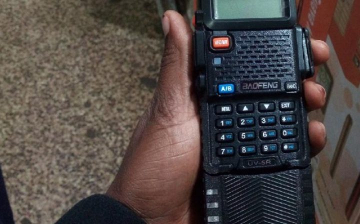
Chapter 2: Getting to know your radio
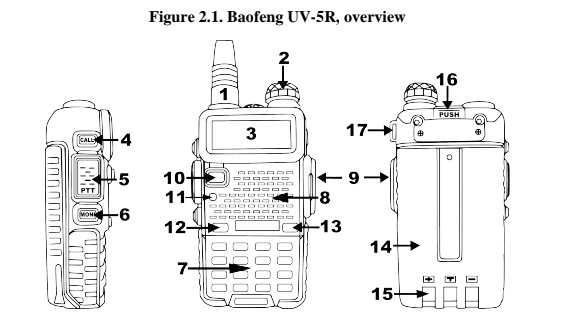
- Antenna, see the section called “Assembly” for details.
- Power / Volume knob, usage discussed in the section called “Power and volume”.
- Two-line LCD
- Call key
- PTT key, usage discussed in the section called “Making a call”.
- Monitor key
- Keypad
- Speaker and microphone
- Accessory jack
- VFO/MR mode key
- Status LED
- A/B select key
- Band select key
- Battery pack, see the section called “Charging and battery maintenance” for detais.
- Battery contacts
- Battery release latch
- Lanyard loop
- LED flashlight, (not marked) situated between antenna and power/volume knob. See the section called “Side key 2 – MONI (Monitor and Flashlight)” for more information.
The main display
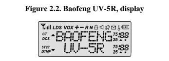
The transceiver is fitted with a seven character by two line dot-matrix alphanumeric LCD, with auxiliary icons for miscellaneous features.
Table 2.1. LCD icon summary
| Icon | Description |
| 188 | Memory channel |
| 25.72 | Least significant modifiers. |
| CT | CTCSS enabled |
| DCS | DCS enabled |
| +,- | Frequency shift direction if enabled |
| S | Dual watch enabled |
| VOX | VOX enabled |
| R | Reverse function enabled |
| N | Narrowband enabled |
| | Battery level indicator |
| | Keypad lock enabled |
| L | Transmit power set to Low |
| | Indicates active band or channel |
| | Signal Strength Meter |
Unmentioned icons seems to not be implemented in this model of radio.
Even though it is a seven character by two line display, channel memories are only configurable to six character names.
Battery Level Indicator
When the battery level has no bars, the battery is depleated. At this point the radio will start beeping periodically as well as flash the backlight of the display, indicating that you need to change your battery or put your radio in the charger.
Status LED
The status LED has a very simple and traditional design. When you receive a signal it turns green, when you transmit it turns red, and it’s off in standby.
Side key 1 – CALL (Broadcast FM and Alarm)
Press [ Call ] momentarily to start the broadcast FM receiver. Another momentary press turns the broadcast FM receiver off.
Press and hold [ Call ] to activate the alarm function. Press [ Call ] again to turn it off.
Side key 2 – MONI (Monitor and Flash- light)
Press [ MONI ] momentarily to turn on the LED flashlight. Another momentary press turns the flashlight off.
Press and hold [ MONI ] to monitor the signal. This will open up the squelch so you can listen to the unfiltered signal.
VFO / MR -mode key
Pressing [ VFO/MR ] switches between Frequency (VFO) Mode and Memory (MR) mode. Memory mode is sometimes also referred to as Channel mode.
To save frequencies to channel memory you must be in Frequency (VFO) mode.
A/B select key
The [ A/B ]key switches between A (upper) and B (lower) displays. The frequency or channel on the selected display becomes the active listening and transmit frequency or channel.
To save frequencies to channel memory you must be on the A display.
Band key
The [ BAND ]key switches between VHF and UHF bands when in Frequency (VFO) mode.
When listening to broadcast FM, the [ BAND ] key switches between 65-75 MHz and 76-108 MHz bands.
Numeric keypad
The Baofeng UV-5R hand-held transceiver comes standard with a full numeric keypad.
The numeric keys have their secondary function printed on them (in reality it’s rather menu short-cuts, more on that in Chapter 4, Working the menu system).
The [Scan, top right below EXIT, Sharing asterisk/star key] and [Lock, on the bottom right, sharing Pound/Hash key] keys on the other hand have actual secondary functions, scan and keypad lock respectively.

Pound key
In channel mode, the Pound key also acts as a transmit power short key. While in channel mode, momentarily press the Pound key to change between High and Low transmit power. Do note that this is does not alter the transmit power stored to memory for that channel, it only affects the current session. Switching to another channel or another operating mode (including broadcast FM) will reset transmit power to what’s stored in channel memory.
Keypad Lock
The Baofeng UV-S5R features a keypad lock that locks out all keys except for the three side keys. To enable or disable the keypad lock, press and hold the Lock key for about two seconds. You can also enable so that the radio automatically locks the keypad after ten seconds from the menu, see Chapter 4, Working the menu system and ??? in Appendix B, Menu definitions for details.
Star key
A short momentary press of the key enables the reverse function (see Chapter 11, Re-peaters).
When listening to broadcast FM a momentary press will start the scanning. Scanning in broadcast FM will stop as soon as an active station is found, regardless of scanner resume method.
To enable the scanner, press and hold the [ * scan ] key for about two seconds. See Chapter 5, Scanning for details.
Menu and function keys
The [ MENU ] key, used to enter the menu and confirm menu options.
The [ UP ] and [ DOWN ] keys are used to navigate through the menu as well as select channels and step up or down in frequency (depending on operating mode).
The EXIT key is used to exit menus and cancel menu options.
For a more in-depth explanation on how to work the menu see Chapter 4, Working the menu system.
Accessory jack
The accessory jack on the Baofeng UV-5R is a Kenwood compatible two(2)-pin design.
Figure 2.4. Typical 2 pin Kenwood headset configuration.
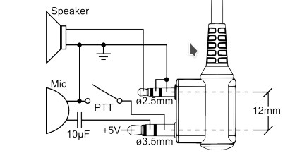
The Kenwood 2-pin connector has one 3.5mm TRS plug, and one 2.5mm TS plug, spaced 12mm apart.
To attach accessories such as headsets, speaker-mics, or programming cables, align the connectors and push in fully.
The fit isn’t always perfect on cheap cables and connectors and may require a bit of force to wiggle them in completely.
[warning] Make sure the radio is off before attaching any accessories.
Chapter 3. Basic Use
Power and volume
Before we turn the power on, make sure you have attached the battery and antenna as described in Chapter 1, Initial setup.
Turning the unit on
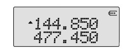
To turn the unit on, simply rotate the volume/power knob clockwise until you hear a “click”. If your radio powers on correctly there should be an audible double beep and the display and backlight should turn on, looking something like this:
Figure 3.1. First power-on, display
You can get additional information about your radio when you turn it on by holding down miscellaneous keys as you turn it on.
Holding down the [ 3 save] key while turning on the radio provides you with the firmware version.
Holding down the [ 6 ABR] key while turning on the radio provides you with what is most likely a control or manufacturing date and a hardware revision number. (It should be noted that this is not confirmed and pure speculation from the community.)
Turning the unit off
Turn the volume/power knob counter-clock wise all the way until you hear a “click”. The unit is now off.
Adjusting the volume
To turn up the volume, turn the volume/power knob clock-wise.
To turn the volume down, turn the volume/power knob counter-clock-wise. Be careful not to turn it too far, as you may inadvertently turn your radio off.
By using the monitor function, enabled from the [MONI] key below the PTT, you can more easily adjust your volume by adjusting it to the un-squelched static.
Making a call
Press and hold the PTT button on the side of the radio body to transmit. While transmit- ting, speak approximately 3-S5cm from the microphone. When you release the PTT your transceiver will go back to receive mode.
Channel selection
There are two modes of operation. Frequency (VFO) mode, and Channel or Memory (MR) mode.
For everyday use, Channel (MR) mode is going to be a whole lot more practical than Fre- quency (VFO) mode. However, Frequency (VFO) mode is very handy for experimenta- tion out in the field. Frequency (VFO) mode is also used for programming channels into memory. For details on how to program your transceiver see Chapter 10, Programming.
Ultimately which mode you end up using will depend entirely on your use case.
Frequency (VFO) mode
In Frequency (VFO) mode you can navigate up and down the band by using the [UP ] and [ DOWN] keys. Each press will increment or decrement your frequency according to the frequency step you’ve set your transceiver to. For details on how to set the frequency step on your transceiver see Chapter 4, Working the menu system and the section called “1 STEP – Frequency Step” in Appendix B, Menu definitions.
You can also input frequencies directly on your numeric keypad with kilohertz accuracy. However, the radio will floor to the nearest frequency that correspond to your frequency step. In other words, when you input frequencies with greater than 1kHz resolution (such as 145.6875 MHz in the example below), always round your input up.
The following example assumes the use of a 12.5kHz frequency step.
Example 3.1. Entering the frequency 145.6875 MHz on display A
1. Use the [ VFO/MR] key to switch to Frequency (VFO) mode
2. Press [A/B ] until the [Up arrow ] appears next to the upper display (display A).
3. Press the [ BAND] key until you get to VHF. The display should read somewhere be- tween 136 and 174 MHz.
4. Enter [ 1STEP] [4VOX ] [5WN ] on the numeric keypad, it should look something like this:
Figure 3.2. Half-entered frequency input.
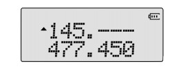
5. Now, for the final four digits. Note that you can only enter three decimals on the keypad, if you type 687 it wont work. So how do you get the fourth and final digit 5 in there? By rounding 145.6875 up to 145.6880 MHz.
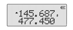
Enter[ 6 ABR ] [ 8 DEEP] [8 DEEP ] on the numeric keypad, if all went well the display should look something like this:
Figure 3.3. Successful frequency input
Just because you can program in a channel does not mean you’re automatically authorized to use that frequency.
Transmitting on frequencies you’re not authorized to operate on is illegal, and in most jurisdictions a serious offence. If you get caught transmitting without a license you can and will get fined, and in worst case sent to jail.
However, it is legal in most jurisdictions to listen. Contact your local regulatory body for further information on what laws, rules and regulations apply to your area.
Channel (MR) mode
The use of Channel (MR) mode is dependent on actually having programmed in some channels to use. To find out more on how to program channels see Chapter 10, Programming.
Once you have channels programmed and ready, you can use the [UP] and [DOWN]keys to navigate between channels.
If you have channels programmed with Transmit power set to Low, you can use the key [ Pound/Lock] to momentarily switch over to high power if you’re having trouble getting through.
Part Il. Advanced topics
Part two covers the more advanced topics, such as setup of repeater offset and programming via computer link.
- Chapter 4, Working the menu system
- Chapter 5, Scanning
- Chapter 6, Dual Watch
- Chapter 7, DTMF
- Chapter 8, Selective calling
- Chapter 9, Customization
- Chapter 10, Programming
Chapter 4. Working the menu system
For a complete reference on available menu items and parameters, see Appendix B, Menu definitions.
If your radio is set to Memory (MR) mode, the following menu items will not take any effect:
STEP, TXP, W/N, CTCSS, DCS, S-CODE, PTT-ID, BCL, SFT-D, OFFSET, MEM-CH, BAND
Basic use
Procedure 4.1. Using the menu with arrow keys
- Press the (MENU) key to enter the menu.
- Use the [ UP] and [DOWN] keys to navigate between menu items.
- Once you find the desired menu item, press (MENU) again to select that menu item.
- Use the [ UP] and [DOWN] keys to select the desired parameter.
- When you’ve selected the parameter you want to set for a given menu item;
- To confirm your selection, press [END and it will save your setting and bring you back to the main menu.
- To cancel your changes, press [EXIT ] and it will reset that menu item and bring you out of the menu entirely.
- To exit out of the menu at any time, press the [EXIT] key.
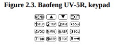
Using short-cuts
As you may have noticed if you looked at Appendix B, Menu definitions, every menu item has a numerical value associated with it. These numbers can be used for direct access of any given menu item.
The menu is also organized in such a way that the ten most common functions are on top, and as can be seen in Figure 2.3, “Baofeng UV-5R, keypad”, these are also printed on the keypad so you don’t have to remember them all.
The parameters also have a number associated with them, see Appendix B, Menu defi- nitions for details.
Procedure 4.2. Using the menu with short-cuts
- Press the [MENU ] key to enter the menu.
- Use the numerical keypad to enter the number of the menu item.
- To enter the menu item, press the [ MENU] key.
- For entering the desired parameter you have two options:
- Use the arrow keys as we did in the previous section; Or
- Use the numerical keypad to enter the numerical short-cut code.
- And just as in the previous section;
- To confirm your selection, press [MENU ] and it will save your setting and bring you back to the main menu.
- To cancel your changes, press [EXIT ] and it will reset that menu item and bring you out of the menu entirely.
- To exit out of the menu at any time, press the [ EXIT] key.
All further examples and procedures in this manual will use the numerical menu short- cuts.
Chapter 5. Scanning
The Baofeng UV-5R features a built in scanner for the VHF and UHF bands. When in Frequency (VFO) mode it will scan in steps according to your set frequency step. In Channel (MR) mode it will scan your channels. At approximately three frequencies per second, it’s not the fastest scanner in the world, but it is nonetheless a useful feature to have at times.
To enable the scanner, press and hold the [ * SCAN] key for about two seconds.
Press any key to exit scanning mode.
Scanning modes
The scanner is configurable to one of three ways of operation: Time, carrier or search, each of which are explained in further details in their respective section below.
Procedure 5.1. Setting scanner mode
- Press the [ MENU] key to enter the menu.
- Enter [1STEP ] [8BEEP ] on your numeric keypad to come to scanner mode.
- Press the [MENU ] key to select.
- Use the [Up ] and [ Down] keys to select scanning mode.
- Press the [MENU ] key to confirm and save.
- Press the [ EXIT] key to exit the menu.
Time operation
In Time Operation (TO) mode, the scanner stops when it detects a signal, and after a pre set time out time of inactivity, it resumes scanning.
Carrier operation
In Carrier Operation (CO) mode, the scanner stops when it detects a signal, and as soon as the signal goes away it resumes scanning.
Search operation
In Search Operation (SE) mode, the scanner stops when it detects a signal.
To resume scanning you must press and hold the [*SCAN ] key again.
Tone Scanning
In frequency mode you can scan for CTCSS tones and DCS codes on active frequencies.
To scan for CTCSS or DCS on active channels, follow these steps:
Procedure 5.2. Tone scanning
- Press the [MENU ] key to enter the menu.
- Enter one of the following on the numeric keypad:
- [1STEP] [0QSL ] to scan for DCS codes, or
- [1STEP ] [1STEP ] to scan for CTCSS sub-tones.
- Press the [MENU ] key to select.
- Press the [*SCAN] key momentarily, CT or DCS will start flashing in the display as the radio starts scanning. Once it finds a tone or code in use, it will beep and stop flashing, indicating that a tone or code has been found.
- Press the [*SCAN] key to confirm.
- Press the [*SCAN]key to exit the menu system
If you wish to communicate with a party after finding out what CTCSS or DCS settings they’re transmitting with, configure your transmit CTCSS or DCS according with what the scanner set for your receive CTCSS or DCS. For details see Chapter 8, Selective calling.
Chapter 6. Dual Watch
In certain situations, the ability to monitor two channels at once can be a valuable asset. This can be achieved in one of two ways. You can either have one receiver in your radio and flip-flop between two frequencies at a fixed interval (known as Dual Watch), or you can equip a radio with two receivers (known as Dual Receive or Dual VFO). The former method is cheaper to implement and far more common than the latter.
The Baofeng UV-SR features Dual Watch functionality (single receiver) with the ability to lock the transmit frequency to one of the two channels it monitors.
Certain functions are not available while in dual watch mode:
- You cannot use the reverse function.
- You cannot use the [Pound/Lock] key to switch between high and low transmit power in channel mode.
- You cannot save duplex channels.
Procedure 6.1. Enabling or disabling Dual Watch mode
- Press the [ MENU] key to enter the menu.
- Enter [7TDR] on the numeric keypad to get to Dual Watch.
- Press [MENU] to select.
- Use the [UP] and [DOWN] keys to enable or disable.
- Press the [MENU] key to confirm.
- Press the [EXIT] key to exit the menu.
Due to the way the Baofeng UV-SR is constructed, whenever one of the A and B channels goes active, it will default to transmit on that channel. This behaviour can be highly inconvenient, especially if you’re listening to a frequency you’re not allowed to transmit on. Luckily there is a menu option available to lock the transmitter to one of the A and B channels.
Procedure 6.2. Locking the Dual Watch transmit channel
- Press the [MENU] key to enter the menu.
- Enter [3SVAE] [4VOX] on the numeric keypad to get to TDR-AB.
- Press [MENU] to select.
- Use the [UP] and [DOWN] keys to select A (upper) or B (lower) displays.
- Press the [MENU] key to confirm.
- Press the [EXIT] key to exit the menu.
If you want to momentarily override the lock without having to set the menu option to OFF, you can do so by pressing the [A/B] key an instant before pressing the PTT.
Another option for overriding the lock momentarily, is to program in the reverse of Channel (MR) mode into Frequency (VFO) mode and using the [VFO/MR] key to swap between primary and secondary channels.
Chapter 7
DTMF is an in-band signalling method using dual sinusoidal signals for any given code. Originally developed for telephony systems, it has proved a very versatile tool in many other areas.
In two-way radio systems, DTMF is most commonly used for automation systems and remote control. A common example would be in amateur radio repeaters where some repeaters are activated by sending out a DTMF sequence (usually a simple single-digit sequence).
Table 7.1. DIMF frequencies and corresponding codes
| 1209 Hz | 1336 Hz | 1477 Hz | 1633 Hz | |
| 697 Hz | 1 | 2 | 3 | A |
| 770 Hz | 4 | 5 | 6 | B |
| 852 Hz | 7 | 8 | 9 | C |
| 941 Hz | * | 0 | # | D |
The Baofeng UV-5R has a full implementation of DTMF, including the A, B, C and D codes.
The numerical keys, as well as the [*SCAN] and [POUND/UNLOCK ], keys correspond to the matching DTMF codes as you would expect. The A, B, C and D codes are located in the [MENU], [UP], [DOWN] and [EXIT] keys respectively.
To send DTMF codes, press the key(s) corresponding to the message you want to send while holding down the PTT key.
If you have the keypad lock enabled on your radio, you can still send DTMF tones the regular way without having to unlock your radio.
Chapter 8. Selective calling
Some times when you’re working with larger groups of people using the same channel, things can get very crowded, very fast. To minimize this problem, several methods of blocking out unwanted transmissions on your frequency has developed. In general, there are two forms of selective calling in two-way radio systems: Group calling, and individ- ual calling.
Group calling, as the name suggest, is a one-to-many form of communication. Every radio in your working group is configured the same way and any radio will make contact with every other radio in the group.
Individual calling, some times also known as paging, is a one-to-one form of communi- cation. Every radio is programmed with a unique ID code. And only by sending out a matching code can you get that radio to open up to your transmissions.
The Baofeng UV-SR features three different ways of group calling:
- CTCSS
- DCS
- Tone-burst (1750Hz)
The Baofeng UV-S5R does not feature any form of individual calling.
Using these features does NOT mean that others won’t be able to listen in on your transmissions.
They only provide a method to filter out unwanted incoming transmissions. Any communications made while using these features will still be heard by anyone not employing filtering options of their own.
Also, you cannot change the CTCSS or DCS settings while in memory (MR) mode.
CTCSS and 1750Hz tone-burst are also popular methods among amateur radio operators to open up repeaters.
CTCSS
CTCSS is set with menus 11 R-CTCS and 13 T-CTCS.
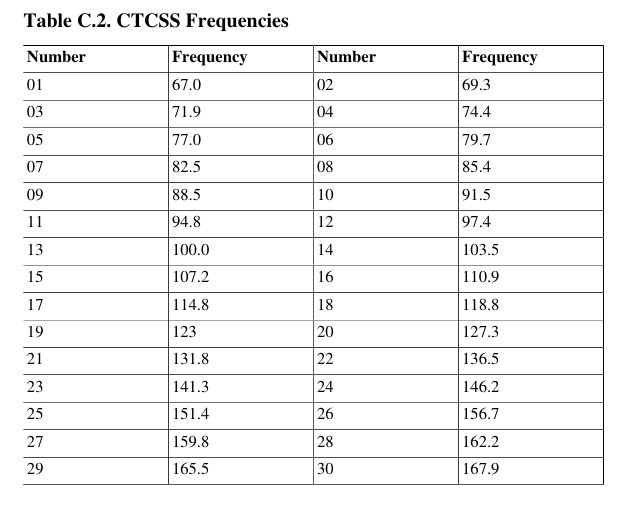
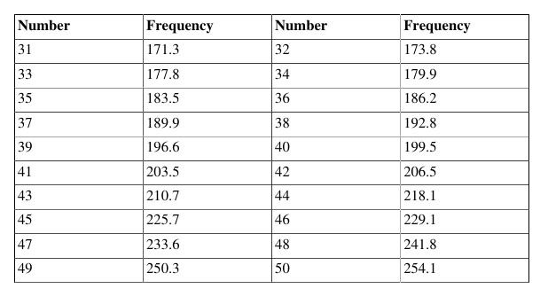
For a complete list of available CTCSS codes and corresponding sub-tone frequencies, see Table C.2, “CTCSS Frequencies” in Appendix C, Technical specifications.
Procedure 8.1. CTCSS setup how-to
- Press the [MENU] key to enter the menu.
- Enter [1STEP] [1STEP] on the numeric keypad to get to receiver CTCSS.
- Press [MENU] to select.
- Enter desired CTCSS sub-tone frequency in hertz on the numeric keypad.
- Press [MENU] to confirm and save.
- Enter[1STEP] [3SAVE] on the numeric keypad to go to transmitter CTCSS.
- Press[MENU] to select.
- Enter desired CTCSS sub-tone frequency in hertz on the numeric keypad. Make sure it’s the same frequency as that you entered for receiver CTCSS.
- Press [MENU] to confirm and save.
- Press [MENU] to exit the menu system.
To turn CTCSS off, follow the same procedure but set it to off with the key instead of selecting a CTCSS sub-tone frequency.
For more information see the section called “11 R-CTCS – Receiver CTCSS” and the section called “13 T-CTCS – Transmitter CTCSS” in Appendix B, Menu definitions.
DCS
DCS is set with menus 10 R-DCS and 12 T-DCS.
For a complete list of available DCS codes, see Table C.1, “DCS Codes” in Appendix C, Technical specifications.
Procedure 8.2. DCS setup how-to
- Press the [MENU] key to enter the menu.
- Enter [1STEP] [0SQL ] on the numeric keypad to get to receiver DCS.
- Press [MENU] to select.
- Enter desired DCS code on the numeric keypad.
- Press [MENU] to confirm and save.
- Enter [1STEP] [2TXP] on the numeric keypad to go to transmitter DCS.
- Press [MENU] to select.
- Enter desired DCS code on the numeric keypad. Make sure it’s the same code as 9.that you entered for receiver DCS.
- Press [MENU] to confirm and save.
- Press [MENU] to exit the menu system.
To turn DCS off, follow the same procedure but set it to off with the key instead of selecting a DCS code.
For more information see the section called “10 R-DCS – Receiver DCS” and the section called “12 T-DCS – Transmitter DCS” in Appendix B, Menu definitions.
1750Hz Tone-burst
To send out a 1750Hz tone-burst, press the [BAND] key while holding down the PTT.
No further configuration required to use this feature.
If you have the keypad lock enabled on your radio, you can still send a 1750Hz tone the regular way without having to unlock your radio.
Chapter 9. Customization
The Baofeng UV-5R allows for customization of both the power-on message (via com- puter link only), and the backlight colour during the three states of the transceiver (Trans- mit, Receive and Standby).
Display
The LCD on the Baofeng UV-SR is backlit by multi-colour LEDs, the colour of which can be pre-set from the menu system into a variety of colours.
To change the colours, follow these steps:
Procedure 9.1. Changing backlight colour
- Press the [MENU]key to enter the menu.
- Enter one of the following on your numeric keypad:
- [2TXP] [9TOT ] to change the Standby colour.
- [3SAVE] [0SQL] to change the receive colour.
- [3SAVE] [1STEP]to change the transmit colour.
- Press [MENU] key to select.
- Use the [UP] and [DOWN]keys to pick the desired colour.
- Press [MENU] to confirm and save.
- Press [EXIT] to exit the menu.
To change the time the backlight stays on for your LCD, follow these steps:
Procedure 9.2. Setting backlight time-out
- Press the [MENU] key to enter the menu.
- Enter [6ABR] on your numeric keypad to come to backlight time out.
- Press [MENU] key to select.
- Use the [UP] and [DOWN] keys to pick the desired colour.
- Press [MENU] to confirm and save.
- Press [EXIT] to exit the menu.
For details see the section called “29 WT-LED – Display back-light colour, Standby” and onward in Appendix B, Menu definitions.
Power-on message
The power-on message can only be set via computer link, see the section called “Com- puter programming” for details on how to set up a link with your computer.
The following instructions assume that you’ve already established a link using the Baofeng software from a computer running Windows, and that the Baofeng software is already installed and running.
Procedure 9.3. Setting the power-on-message
- Click other in the menu bar, a dialogue box titled “Other” should have popped up.
- In the box titled “Power On Message”, there are two text fields representing the two lines on your LCD. Enter the desired text in the fields.
- Click Write to write your changes to the radio.
Even though the software has eight(8) character wide text fields for the power-on message, be aware that the display on the UV-5R can only display a maximum of seven(7) characters.
Make sure that menu item 38 is set to MSG, otherwise your message wont be dis- played. see Chapter 4, Working the menu system for details on how to navigate the menu.
Some times it takes the Baofeng software more than one try to connect to your radio. If you see a dialogue box popping up stating that you have a connection failure, close the dialogue box and click read or write again.
Chapter 10. Programming
Memory channels are an easy way to store commonly used frequencies so that they can easily be retrieved at a later date.
The Baofeng UV-5R features 128 memory channels that each can hold: Receive and transmit frequencies, transmit power, group signalling information, bandwidth, ANI/ PTT-ID settings and a six character alphanumeric identifier or channel name V
Manual programming
Manual programming is somewhat fiddly until you get used to it, especially when pro- gramming in duplex channels. Note that the ANI and S-CODE IDs can only be set from a computer. When programming channels it is important to remember that you can only save memory channels when working on the upper display in VFO mode.
To create a new channel, start by switching your radio to Frequency (VFO) mode using the [VFO/MR] key. When in Frequency (VFO) mode, select your desired receive frequency using the numerical keypad. After that, use the menu system to configure the finer details of the channel you’re wanting to program to memory, such as transmit power, bandwidth, CTCSS or DCS and more.
For more information on how to use the menu system see Chapter 4, Working the menu system and Appendix B, Menu definitions. Information regarding how to set up CTCSS and DCS can be found in Chapter 8, Selective calling.
Simplex channels
The following steps assume that you’re in Frequency (VFO) mode and that you’ve en- tered the desired frequency to store to memory.
- Press the [MENU] key to enter the menu.
- Enter [2TXP] [7TDR] on the numerical keypad to get to MEM—CH.
- Press [MENU] to select.
- Use the [UP] and [DOWN] keys to select a memory channel, or enter it directly on the numerical keypad.
- Press the [MENU] key to confirm.
- Press the [EXIT]key to exit the menu.
1ANI/PTT-ID and channel name can only be set from a computer.
Switch to Channel (MR) mode with the [VFO/MR] key to test your new channel. If you would like to name your channel you will need to do that from a computer. More on that in the section called “Computer programming”.
Duplex channels
The following assumes you’ve set up a duplex channel in VFO mode on the upper dis- play, as described in Chapter 11, Repeaters, and that you’re still in VFO mode.
- Save as you would a regular simplex channel, as described in the previous section.
- Press the [*SCAN] key momentary to get into reverse mode.
- Save that again to the same memory channel just as in step one(1).
Switch to Channel (MR) mode with the [VFO/VR] key to test your new channel. If you would like to name your channel you will need to do that from a computer. More on that in the section called “Computer programming”.
Computer programming
This section assumes you know where to get a hold of your software and how to install it, that you’ve already installed your software and that you know how to find out what port your programming cable is hooked up to.
Attaching the programming cable
Before attaching the cable, make sure your radio is turned off.
To attach the cable, uncover the accessory port behind the rubber flap on the right side of the radio body (see Figure 2.1, “Baofeng UV-5R, overview”), align the connectors and push in firmly.
Attach the USB (or DE9 in the case of standard RS-232) connector to your computer and start your programming software. You may now turn on your radio.
Baofeng software
Before starting the software, follow the steps in the section called “Attaching the pro- gramming cable”.
When you first open up the Baofeng programming software, it may default to Chinese. To change the language to English, go to the second rightmost menu. There you will find a list of available languages, select English.
When you start the Baofeng programming software you will be greeted by the Channel Information window. This is where you enter the channel information for your memory channels. If the Channel Information window doesn’t show automatically, you can bring it up by going to Edit —-> Channel Information.
Before we start adding channels, go to Communication to select the port your cable is attached to. Next goto Program -> Read from radio and click Read to read in any existing channel information on the radio. This is also a good way to test the connection of the programming cable. If the read is successful the LED on your radio will start flashing red indicating that the radio is transmitting data to the computer.
The Baofeng programming software has been known to fail on connect the first try. If your connection fails, just try to read or write again.
If it continues to fail, check the connection of your cable and that you’ve configured your port properly in the programming software.
The Channel Information window in the Baofeng software features a simple and easy to use spreadsheet style interface. Some columns are obvious, others aren’t as transparent as to what their purpose is. However, in most cases the default values tend to be the appropriate ones.
Channel Information window, column definitions
- Channel: Channel number
- Band: What band, defaults to both VHF and UHF.
- RX Frequency: Receive frequency.
- TX Frequency: Transmit frequency. Defaults to the receive frequency.
- CTCSS/DCS Dec: Receiver CTCSS or DCS. Defaults to OFF.
- CTCSS/DCS Enc: Transmitter CTCSS or DCS. Defaults to OFF.
- TX Power: Transmit power. Defaults to HIGH.
- W/N: Wideband or Narrowband operation. Defaults to W for Wideband.
- PTT-ID: Enables and sets position of PTT-ID. Defaults to OFF.
- BusyLock: Busy Channel Lock-out. Defaults to OFF.
- Scan_Add: Add to scanner list. When enabled the channel is included in scan- ning mode. Defaults to ON.
- SigCode: Signal Code, group ID for the channel. Defaults to 1.
- CH-Name: Channel name.
You can in theory edit any field in a row at any time, however the software seems to work best when you work from left to right.
To add a new channel, go to the row for the channel number you want to edit (you do not have to go sequentially, you can skip channel numbers if you so desire) and follow these steps:
Procedure 10.1. Adding a channel
- Select the Band.
- Click in the RX Frequency field next to it and enter your receive frequency.
- Click on the TX Frequency field, and the rest of the row should fill in automat- ically with default values (except for CH-Name which will be kept blank).
- If you’re adding a duplex channel you can go ahead and enter your transmit fre- quency directly.
- After that it’s all just a matter of adding all the extra information and features needed for the channel based on your requirements.
- When you’re done you can add an optional six character Channel Name in the CH— Name field.
Repeat for all the channels you want to add.
To delete a channel, simply go to the RX Frequency field of that channel’s row, erase it and click on another field. The row should now erase itself.
When you’re done adding and editing channels you will want to write them to the radio. To write your information to the radio, goto Program —> Write to radio and click Write. Ona successful write sequence the radio will start flashing green indicating that it is receiving data. When all data blocks have been sent from the computer the radio will restart itself.
Radio to radio cloning
The Baofeng UV-SR is capable of cloning between radios, meaning if you have one radio set up just the way you like it (the reference or “master” radio) and want another radio configured in exactly the same way (the “slave” radio), you just hook a cable between them and copy the information over.
Procedure 10.2. Cloning radios
- Attach your cloning cable in much the same way you attach a programming cable, except for where you put the other end into another radio’s accessory port rather than a computer.
- Turn on the slave radio, (the radio you want to clone to).
- Turn on the master radio, (the radio you want to clone from) while holding down the [MONI] key.
- The master will show COP ING in the display, and if makes a successful connection to the slave it will start flashing red to indicate it’s transmitting data. The slave will at that same time flash green to indicate it’s receiving data.
- When LEDs turn off, the radio’s will restart and the cloning operation is completed.
Part Ill. How-to and setup guides.
Part three covers is a collection of how-to documents to help you set up your radio for specific working environments.
- Chapter 11, Repeaters
- Chapter 12, Automatic Number Identification
- Chapter 13, Application Specific Setup
Chapter 11. Repeaters
A radio repeater is an automated transceiver in a fixed location. Usually mounted high up on hill tops or on tall buildings, but sometimes they operate within buildings for internal use. A repeater takes one signal and relays it, usually after amplifying it by orders of magnitude. This can be very handy, as this enables you to use a small low powered handheld two-way transceiver such as the Baofeng UV-SR to reach great distances.
Whether you’re a commercial (business or government) user or an amateur radio operator, chances are you’ll be dealing with a repeater system sooner or later. To find out what settings to use to use your local repeater, ask your employer or someone at your local IARU member organization for details.
A common type of repeater, is the duplex repeater. In a duplex repeater system, the repeater transmits and receives simultaneously, but on different frequencies. To utilize this type of repeater, your radio have to be capable of transmitting and receiving on different frequencies on the same memory channel. How you use this kind of repeater is by setting the receive frequency of your radio to the output frequency of the repeater, and the transmit frequency of your radio to the input frequency of the repeater. Often times, the transmit frequency to use isn’t explicitly stated, but rather an offset relative your receive frequency is specified. This is conveniently enough also how the Baofeng UV-5R natively handles repeater setup, by specifying offset rather than transmit frequency.
The following instructions assume that you know what transmit and receive frequencies your repeater employs and that you’re authorized to use it.
Procedure 11.1. Repeater setup
- Set the radio to Frequency (VFO) mode with the [VFO/MR] key.
- Enter the repeaters output (your receiving) frequency by either using the [UP] and [DOWN] keys, or by entering it directly on the numerical keypad.
- Press the [MENU] key to enter the menu.
- Enter [2TXP] [6ABR] on the numeric keypad to get to frequency offset.
- Press [MENU] key to select.
- Use the [UP] and [DOWN] keys and the numerical keypad to enter the specified frequency offset. See the section called “26 OFFSET – Frequency shift amount” for details.
- Press [MENU] to confirm and save.
- Enter [2TXP] [5WN] on the numeric keypad to get to offset direction.
- Use the [UP] and [DOWN] keys to select + (positive) or — (negative) offset.
- Press [MENU] to confirm and save.
- Optional:
- Save to memory, see the section called “Manual programming” for details.
- Setup CTCSS, see the section called “CTCSS” for details.
- Press [EXIT] to exit the menu.
If everything went well, you should be able to make a test call through the repeater. If you’re experiencing problems making a connection to the repeater, check your settings and/or go through the procedure again.
Certain Amateur Radio repeaters (especially in Europe) use a 1750Hz tone burst to open up the repeater. To see how this is done with the Baofeng UV-5R, see the section called “1750Hz Tone-burst”.
If you’re still unable to make a connection, contact the person in charge of the radio system with your employer or your local amateur radio club, as the case may be.
If you for some reason want to listen to the repeater’s input frequency instead, press [*SCAN ] momentarily and you’ll reverse your transmit and receive frequencies (reverse function not available while in Dual Watch mode).
This is indicated in the LCD on the radio with a R in the top row, next to the + and — for the offset direction.
Chapter 12. Automatic Number Identification
In dispatch environments it’s common to have a system in place that will allow radios to automatically identify themselves to the dispatcher. This is known as Automatic Number Identification, or sometimes PTT-ID since the radio sends a data burst containing the ID code at the beginning or end of a transmission.
The Baofeng UV-5R uses DTMF signalling for it’s ANI implementation. For details on what settings to use and questions regarding system interoperability, contact the dispatch office with your employer.
Procedure 12.1. Setting ANI code
1.Attach your radio to your computer with a programming cable and open up the Baofeng programming software, see the section called “Computer programming” for details.
2.In the Edit menu, select DIME. This will open up a window called DIMF Encode/Decode.
3.Go to the Program menu, select Read from radio and the Read Data From Radio window will open.
4.Click the Read button. The status LED on the radio will flash red indicating it’s transmitting data.
5.Locate the box named ANI code and enter your personal ID number that you’ve been given from your dispatch office into the text field.
If you use group ID codes in addition to, or instead of personal ID codes, you can enter up to 15 of them in the list to the left in the DIMF Encode/Decode window. These can be assigned on channel by channel basis in the Channel Information, see the section called “Baofeng software” for further details.
6.Check the Press PTT to Send box if you want to transmit your ID before you speak, or;
check the Release PTT to Send box if you want to transmit your ID after you speak.
7.In the Program menu, select Write to radio and the Write Data to Radio window will open.
8.Click the Write button. The status LED on the radio will flash green indicating it’s receiving data.
Unfortunately Baofeng decided to split up related functions in the programming software, so in order to enable ANI we’ll have to open up yet another window and do some final configuration before the radio is ready for use.
The following assumes that you’ve still got the programming software running from earlier.
Procedure 12.2. Setting ANI settings
1.In the Edit menu, select Optional Features. This will open up a very crowded looking window called Optional Features.
2.Go to the Program menu, select Read from radio and the Read Data From Radio window will open.
3.Click the Read button. The status LED on the radio will flash red indicating it’s transmitting data.
4.In the lower left corner there’s a nameless box with a number of drop-down lists, including but not limited to DTMF-ST and PTT_ID.
Use the DIMF-ST drop-down list to select whether to send your personal ANI code (Send ANI DIMF Side Tone), the group code (KB DIMF Side Tone), or both (DIMFST + Send ANI DIMFST).
5.Use the PTT-ID drop-down list to select the position of your ANI data burst; BOT (Beginning of Transmit), EOT (End of Transmit) or BOTH. This is also the option that turns ANI completely off when set to OFF.
6.In the Program menu, select Write to radio and the Write Data to Radio window will open.
7.Click the Write button. The status LED on the radio will flash green indicating it’s receiving data.
Congratulations, you’ve successfully set your radio up for ANI. If you’re experiencing any problems, contact the dispatch office with your employer.
Chapter 13. Application Specific Setup
Commercial Radio Setup
PLMR users in the United States are mandated to move to 12.5 kHz narrowband communication in the 150-174 MHz VHF and 421-512MHz UHF bands by January 1, 2013.
Follow these instructions to set your radio to Narrowband mode:
- Press the [VFO/MR] key to enter frequency mode.
- Press the [MENU] key to enter the menu.
- Enter [5WN] on the numerical keypad.
- Press [MENU] to select.
- Use the [UP] and [DOWN] keys to select between Wide and Narrow(“Narr”).
- Press [MENU] to confirm and save
- Press [EXIT] to exit the menu.
You can also switch by holding down the [5WN] key on the numerical keypad while in frequency mode.
If your employer has a dispatch system that requires your radio to identify via ANI, please see Chapter 12, Automatic Number Identification for detailed instructions on how to set that up on your radio.
To find out what other channels and features needed, please contact your employer.
Amateur Radio Setup
In contrast with Commercial radio operators, who often need very specific requirements to be compatible with a very specific radio implementation, Amateur radio operators tend to need the broadest possible settings in order to be compatible with as many systems as possible. This basically implies turning all the fancy features that you typically might need for a commercial setup off.
In a typical Amateur radio setup the following settings would be recommended:
- Set bandwidth to Wide (menu item 5).
- Turn DCS and CTCSS off (menu items 10 through 13).
- Turn ANI, DTMBFST, S-CODE, PTT-ID off and PTT-LT to Oms (menu items 15 through 17 and 19 through 20).
- Turn off Squelch Tail Elimination (STE) features (menu items 35 through 37).
- Turn roger beep (ROGER) off (menu item 39).
For further information see Appendix B, Menu definitions and Chapter 4, Working the menu system.
MilSim: Airsoft and Paintball
If you live in the USA, it is highly recommended that you and your team get yourselves GMRS licenses to use with your radios. At the time of writing the licensing fee is $85 (per person) and the license is valid for five years. There is no exam involved and any legal resident of the US over the age of 18 can apply for a license with the FCC using form 605. Please visit http://fcc.gov/ for more information.
The following is a list of recommended GMRS channels suitable for Airsoft games, Paintball games, or other recreational military simulations:
462.550 MHz (channel 15) 462.575 MHz (channel 16) 462.600 MHz (channel 17) 462.625 MHz (channel 18) 462.725 MHz (channel 22)
Channel numbers reflect a convention used by Motorola, actual mapping of frequency to channel number may vary between manufacturers.
For those not living in the USA, please contact your local regulatory body in charge of the radio spectrum to see what your options are.
You may be tempted to use FRS (in the USA) or PMR446 (in Europe) frequencies while playing. Do note however that there are restrictions on both of these bands that make this transceiver illegal for use.
Not only do you need a radio with a maximum of 500mW output power (the Baofeng UV-5R provides at minimum twice that), you also aren’t allowed to use a radio with a detachable antenna or a radio that can be used outside of the FRS or PMR446 bands.
In the US there is one exception to that rule, and that is FRS+GMRS combo units, however they are still restricted to 500mW output power on the FRS frequencies, and they still have to be manufactured with a fixed integral antenna.
Appendix A. Troubleshooting
| Symptom | Possible cause | solution |
| The radio doesn’t start. | The battery is too low.The battery isn’t correctlyinstalled. | Change or recharge the battery. Remove the battery and re-install it. |
| The battery dies quickly. | The battery is dead.The battery isn’t fully charged. | Purchase a new battery.Recharge the battery. |
| The LED indicates recep-tion, but the speaker issilent. | Volume is too low.CTCSS or DCS enabled. | Turn up the volume.Change your CTCSS orDCS to match those you’retrying to communicate with.Or turn CTCSS or DCS off. |
| Others can’t hear my trans-mission. | Their CTCSS or DCS set-tings doesn’t match yours.You’re too far apart. | Change your CTCSS orDCS settings to match yourpeers.Move in closer. |
| The radio transmits without touching the PTT. | The VOX is enabled. VOX sensitivity is too high. | Turn VOX off.Turn down VOX sensitivity. |
Appendix B. Menu definitions
See Chapter 4, Working the menu system for more info about using the menu-system.
0 SQL – Squelch Level
Selects the squelch noise threshold.
| Values | Notes | Default value |
| 0-9 | 3 | |
Setting the squelch to 0 will open up the squelch entirely.
1 STEP – Frequency Step
Selects the step in frequency when using the (UP) and (DOWN) keys. This is also the interval the scanner will run at.
| Key | Values (kHz) | Notes | Default value |
| 0 | 2.5K | 25.0K | |
| 1 | 5.0K | ||
| 2 | 6.25K | ||
| 3 | 10.0K | ||
| 4 | 12.5K | ||
| 5 | 25.0K |
This does only affect the radio when in Frequency (VFO) Mode.
2 TXP – Transmit Power
Transmit power is only settable in Frequency(VFO) Mode. In Memory(MR) Mode transmit power will be set to the level programmed in memory for any given channel.
| Key | Values | Notes | Default value |
| 0 | HIGH | 4W | HIGH |
| 1 | LOW | 1W |
3 SAVE – Battery Save
Sampling ratio of the Receiver to acknowledge a signal
| Values | Notes | Default value |
| 1-4 | 3 | |
| OFF |
4 VOX – Voice Operated TX
Adjusts the sensitivity of the VOX feature, if enabled.
| Values | Notes | Default value |
| 1-10 | OFF | |
| OFF |
The lower the setting, the louder your voice have to be in order to engage the transmitter.
5 WN – Wideband / Narrowband
Sets maximum band deviation.
| Key | Values | Notes | Default value |
| 0 | WIDE | 5kHz | WIDE |
| 1 | NARR | 2.5kHz |
In the USA, FCC part 90 radios are mandated to switch over to Narrowband communication by January 1st 2013. Meaning all commercial users. This does not affect Amateur Radio operators.
6 ABR – Display Illumination Time
Time-out for the LCD back-light.
| Values (seconds) | Notes | Default value |
| 1-5 | 5 | |
| OFF |
7 TDR – Dual Watch
When enabled it allows you to monitor two frequencies simultaneously.
| Key | Values | Notes | Default value |
| 1 | ON | OFF | |
| 0 | OFF |
It should be noted that this radio does not possess a dual VFO, meaning that the Dual Watch feature is a time sharing operation. Your radio will flip-flop between A and B channels at a fixed rate. This will not allow you to receive two frequencies in parallel.
8 BEEP – Keypad Beep
When enabled your radio will emit an audible tone at every key press.
| Key | Values | Notes | Default value |
| 1 | ON | ON | |
| 0 | OFF |
9 TOT – Transmission Time-out-Timer
Transmission times out after set time. Radio will alert you when your time is up.
| Values (seconds) | Notes | Default value |
| 15-600 | Increments of 15 seconds | 60 |
To use the numeric keypad for input, use the following formula: (T-15)/15 = X, where T is the time in seconds that you want and X is a two digit code on your keypad.
Example: To get 300 seconds, take (300-15) /15 to get 19
10 R-DCS – Receiver DCS
Digital-Coded Squelch(DCS) will block out any signal that isn’t sent with a matching
DCS code.
| Values | Notes | Default value |
| DO23N — D7541 | OFF | |
| OFF |
See Table C.1, “DCS Codes” for a complete reference of DCS codes and their corresponding numerical value. Remember to input any leading zeros when using the numerical keypad. To set it to off, enter code 000.
11 R-CTCS – Receiver CTCSS
Continuous Tone-Coded Squelch System(CTCSS) will block out any signal that isn’t
sent with a matching CTCSS sub-tone.
| Values(Hz) | Notes | Default value |
| 67.0-254.1 | OFF | |
| OFF |
See Table C.2, “CTCSS Frequencies” for a complete reference of CTCSS sub tones. To enter a CTCSS tone on the numerical keypad, enter its frequency directly rather than the numerical code. Remember to input any leading zeros when using the numerical keypad.
To set it to off, enter code 000.
12 T-DCS – Transmitter DCS
Sets the Digital-Coded Squelch(DCS) code for the transmitter.
| Values | Notes | Default value |
| DO23N — D754I1 | OFF | |
| OFF |
See Table C.1, “DCS Codes” for a complete reference of DCS codes and their corresponding numerical value. Remember to input any leading zeros when using the numerical keypad. To set it to off, enter code 000.
13 T-CTCS – Transmitter CTCSS
Sets the Continuous Tone-Coded Squelch System(CTCSS) sub-tone for the transmitter.
| Values | Notes | Default value |
| 67.0-254.1 | OFF | |
| OFF |
See Table C.2, “CTCSS Frequencies” for a complete reference of CTCSS sub tones. To enter a CTCSS tone on the numerical keypad, enter its frequency directly rather than the numerical code. Remember to input any leading zeros when using the numerical keypad.
To set it to off, enter code 000.
14 VOICE – Voice Prompt
When enabled your radio will “talk back” to you, meaning audible confirmation when pressing keys and working the menu system.
| Key | Values | Notes | Default value |
| 1 | ENG | English | ENG |
| 2 | CHI | Chinese | |
| 0 | OFF |
In some versions of the firmware your options may be restricted to ON and OFF.
15 ANI-ID – Automatic Number ID
This can only be set via Computer Linked programming.
| Values | Notes | Default value |
| 80808 |
16 DTMFST – DTMF tone of transmit code
Selects if you should send your S-CODE(DT) or ANI code with the PTT-ID.
| Key | Values | Notes | Default value |
| 1 | DT-ST | S-CODE only | DT+ANI |
| 2 | ANI code only ANI-ST | ||
| 3 | DT+ANI | Both | |
| 0 | OFF |
You cannot set DIMFST while in channel/memory mode.
17 S-CODE – Signal Code
S-—CODE sets your transceiver to one of the fifteen(15) group ID codes. The actual ID codes are only settable from a computer.
| Values | Notes | Default value |
| 1-15 | 1 |
You cannot set S-CODE while in channel/memory mode.
18 SC-REV – Scanner Resume Method
Sets the behaviour of the scanner upon finding active frequencies.
| Key | Values | Notes | Default value |
| 0 | TO | Time Operation | OFF |
| 1 | CO | Carrier Operation | |
| 2 | SE | Search Operation |
- Time Operation: The scanner will resume after a pre set time.
- Carrier Operation: The scanner will resume once the signal disappears.
- Search Operation: The scanner holds on the frequency with detected activity.
19 PTT-ID – When to send the PTT-ID
Sets when to send the PTT-ID (ANI and/or S-CODE) code(s).
| Key | Values | Notes | Default value |
| 1 | BOT | Beginning Of Transmit | OFF |
| 2 | EOT | End Of Transmit | |
| 3 | BOTH | Both BOT and EOT | |
| 0 | OFF |
You cannot set PTT-ID while in channel/memory mode.
20 PTT-LT – Signal code sending delay.
Delay before sending the PTT-ID.
| Values (ms) | Notes | Default value |
| 0-30 | 5 |
21 MDF-A – Channel Mode A Display
Sets the display mode for the upper display.
| Key | Values | Notes | Default value |
| 0 | CH | Channel number | FREQ |
| 1 | NAME | Channel name | |
| 2 | FREQ | Frequency |
Channel name can only be set via Computer.
22 MDF-B – Channel Mode B Display
Sets the display mode for the lower display.
| Key | Values | Notes | Default value |
| 0 | CH | Channel number | FREQ |
| 1 | NAME | Channel name | |
| 2 | FREQ | Frequency |
Channel name can only be set via Computer.
23 BCL – Busy Channel Lock-out
If enabled your radio will prevent you from transmitting on active frequencies.
| Key | Values | Notes | Default value |
| 1 | ON | OFF | |
| 0 | OFF |
24 AUTOLK – Automatic Keypad Lock
If enabled keypad will automatically lock after eight(8) seconds of inactivity.
| Key | Values | Notes | Default value |
| 1 | ON | OFF | |
| 0 | OFF |
25 SFT-D – Frequency Shift Direction
Sets the direction of the transmit offset relative receive frequency.
| Key | Values | Notes | Default value |
| 1 | + | TX frequency =RX+OFFSET | OFF |
| 2 | – | TX frequency =RX-OFFSET | |
| 0 | OFF |
26 OFFSET – Frequency shift amount
Sets the amount of offset on the transmit frequency relative the receive frequency.
| Values (MHz) | Notes | Default value |
| 00.000-69.990 | 00.000 |
To input an offset frequency with the numeric keypad, enter the frequency in 10 mega-
hertz with leading zeroes. For a 2MHz shift, enter [0SQL] [2TXP]. For a 600kHz shift, enter [ 0SQL ] [0SQL ]
[ 6ABR ]
Use the [ UP ] and [ DOWN ] keys to set offsets below 100kHz.
27 MEN-CH – Store a Memory Channel
Stores current settings in memory to the specified channel number.
| Values | Notes | Default value |
| 000-127 | 000 |
28 DEL-CH – Delete a memory channel
Deletes a memory channel at the specified channel number.
| Values | Notes | Default value |
| 000-127 | 000 |
29 WT-LED – Display back-light colour Standby
Sets the back-light colour in standby.
| Key | Values | Notes | Default value |
| 1 | BLUE | PURPLE | |
| 2 | ORANGE | ||
| 3 | PURPLE | ||
| 0 | OFF |
30 RX-LED – Display back-light colour Receive
Sets the back-light colour while receiving a signal.
| Key | Values | Notes | Default value |
| 1 | BLUE | BLUE | |
| 2 | ORANGE | ||
| 3 | PURPLE | ||
| 0 | OFF |
31 TX-LED – Display back-light colour, Transmit
Sets the back-light colour while transmitting a signal.
| Key | Values | Notes | Default value |
| 1 | BLUE | ORANGE | |
| 2 | ORANGE | ||
| 3 | PURPLE | ||
| 0 | OFF |
32 AL-MOD – Alarm Mode
| Key | Values | Notes | Default value |
| 1 | SITE | Cycling tone over the air | SITE |
| 2 | TONE | Radio speaker only | |
| 3 | CODE | Transmit 5s tone followed by Morse | |
33 BAND – Band Selection
Sets the current operating band.
| Key | Values | Notes | Default value |
| 1 | VHF | VHF | |
| 0 | UHF |
34 TDR-AB – Transmit selection while in Dual Watch mode
If enabled, this will force the radio to transmit on the selected frequency when in Dual Watch mode.
| Key | Values | Notes | Default value |
| 1 | A | Upper display | OFF |
| 2 | B | Lower display | |
| 0 | OFF |
35 STE – Squelch Tail Elimination
| Key | Values | Notes | Default value |
| 1 | ON | ON | |
| 0 | OFF |
36 RP-STE – Squelch Tail Elimination through a repeater
| Values | Notes | Default value |
| 1-10 | 5 | |
| OFF |
37 RPT-RL – Delay the squelch tail of repeater
| Values | Notes | Default value |
| 1-10 | OFF | |
| OFF |
38 PONMGS – Power On Message
When enabled it displays a 2 line message on the display. Message can only be set via computer.
| Key | Values | Notes | Default value |
| 1 | FULL | Flash entire LCD | MSG |
| 0 | MSG | Displays a 2 line welcome message |
39 ROGER – Roger Beep
Transmits an audible tone after you release the PTT.
| Key | Values | Notes | Default value |
| 1 | ON | OFF | |
| 0 | OFF |
40 RESET – Restore defaults
Resets the radio to factory defaults, with some exceptions.
| Key | Values | Notes | Default value |
| 1 | VFO | VFO settings only | ALL |
| 0 | ALL | Total reset* |
* RESET>ALL resets everything with the exception of:
- The Power On Message
- The VIP software band limits
- On some firmware it may reset language to Chinese
Appendix C. Technical
General specifications
| SpecificationFrequency Range (MHz) Memory channelsFrequency stabilityFrequency step (kHz)Antenna impedanceOperating temperatureSupply voltageConsumption Mode of operationDuty cycleDimensions (mm)Weight (g) | Value65-108 (Rx only)136-174 (Rx/Tx)400-480 (Rx/Tx)1282.S5ppm2.5/5/6.25/10/12.5/2550 Ohm-20°C to +60°C7.4< 75mA (standby)380mA (reception)< 1 4A (transmission)Simplex or semi-duplex03/03/54 min. (Rx / Tx / Standby)58 x 110 x 32214 |
Transmitter specifications
| Specification RF power (W) Type of modulationEmission class Maximum deviation (kHz)Spurious emissions (dB) | Value4 (UHF high)4 (VHF high)1 (UHF low)1 (VHF low) FM16K#F3E (wideband)11K#F3E (narrowband)< + 5.0 (wideband)< + 2.5 (narrowband)<-60dB |
Receiver specifications
Specification Value Value
- Receiver sensitivity: 0.2uV (at 12dB SINAD)
- Intermodulation: 60dB
- Audio Output: 1000mW
- Adjacent channel selectivity 65/60dB
DCS Table
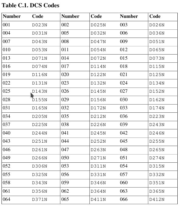
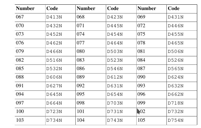
Table C.2 CTCSS Frequencies
Colophon
All linework drawings were recreated in Inkspace [http://inkscape.org/] using the original Baofeng manual artwork as reference
You can download a copy of this user generated documentation project of Baofeng UV-5R here.